Important: Retain all loose parts for later installation unless otherwise noted.
Installation
Preparing the Machine
-
Park the machine on a level surface.
-
Shut off the engine, remove the key, and wait for all moving parts to stop.
-
Allow the machine components to cool before performing maintenance.
-
Disconnect the spark-plug wire.
-
Using a floor jack or overhead lifting device, raise the machine until the tracks are off the ground.
Removing the Snow Tracks
-
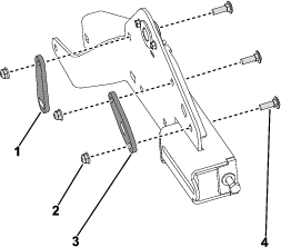
From the sides of the machine, remove and discard the 2 screws (5/16 x 5/8 inch) securing the front brace to the 2 track support assemblies. Remove and discard the front brace.
-
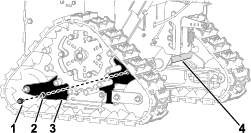
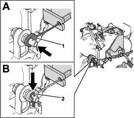
From the left side of the machine, remove and discard the screw (5/16 x 3/4 inch) and flat washer (3/8 x 7/8 inch) securing the track support to the pivot bar (Figure 1). Repeat on the right side.
-
From the left side of the machine, remove the lynch pin from the axle hub. Repeat on the right side.
-
From the left side of the machine, support the drive wheel assembly with the track assembly attached and remove the assemblies from the machine. Repeat on the right side.
-
Remove the 2 drive wheel assemblies from the 2 track assemblies.
-
Remove the 2 hairpins from the pivot bar.
-
Slide and remove the pivot bar from the pivot hub. Discard the pivot bar.
Disassembling the Snow Tracks
Note: Start from the left track and then repeat on the right track.
-
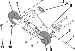
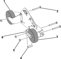
Remove the carriage bolt (3/8 x 3 inch), tensioner bushing, and locknut (3/8 inch) securing the left bogey wheel to the track support (Figure 2). Remove the wheel.
-
Remove the carriage bolt (3/8 x 3 inch), tensioner bushing, and locknut (3/8 inch) securing right bogey wheel to the bogey yoke and track support (Figure 2). Remove the wheel.
-
Remove the carriage bolt (3/8 x 3 inch) and locknut (3/8 inch) securing the bogey yoke to the track support. Remove the bogey yoke from the track support (Figure 2).
-
Remove the axle bushing (Figure 2).
-
Remove the 2 screws (1/4 x 5/8 inch) securing the axle bushing support to the track support. Remove the axle bushing support (Figure 2).
-
Remove the screw (3/8 x 4 inch), tensioner bushing, and washer (3/8 inch) securing the tensioner to the bogey wheel mount (Figure 2). Remove the tensioner.
-
Remove the 2 carriage bolts (5/16 x 3/4 inch) and 2 locknuts (5/16 inch) securing the skid to the track support. Discard the skid.
-
Discard the track support.
Removing the Rear and Bottom Covers
-
Place jack stands under the left and right hydrostatic drive assembly shafts to gain access to the bottom cover. Remove the jack stands or overhead lifting device used in Preparing the Machine.
Note: 2 people may be needed to complete this procedure.
-
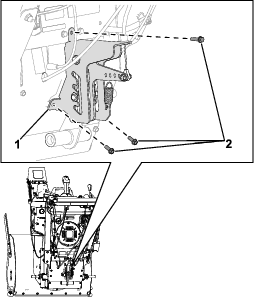
Remove the 3 screws (1/4 x 5/8 inch) securing the height adjuster bracket to the top plate and rear cover. Remove the height adjuster bracket from the plate and cover (Figure 3).
Note: The height adjuster bracket will remain attached to the cables on top of the machine.
-
Remove the 6 screws (1/4 x 5/8 inch) securing the rear cover to the frame side plates.
-
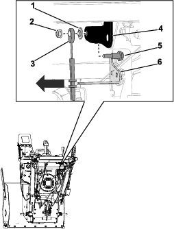
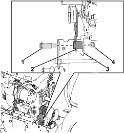
Remove the flange nut (1/4 inch) and shoulder bolt (1/4 x 1 inch) securing the hydrostatic drive cable to the speed selector. Retain the stepped washer (Figure 4).
-
Remove the hydrostatic drive cable from the speed cable bracket and rear cover (Figure 4).
-
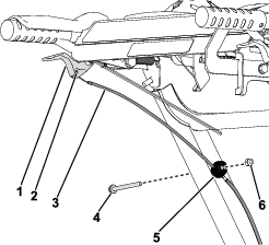
From the left side of the machine, disconnect the clutch cable from the clutch lever (Figure 5). Repeat on the right side.
-
From the left side of the machine, remove the hex nut (1/4 inch) and bolt (1/4 x 2–3/4 inch) securing the cable clamp to the lower handle tube (Figure 5). Repeat on the right side.
Note: The cable clamps will remain on the clutch cables.
-
Unhook the 2 clutch cable springs from the hydrostatic drive assembly.
-
Remove the rear cover with the clutch cables still installed.
-
Remove the 4 screws (1/4 x 5/8 inch) securing the bottom cover to the bottom of the machine. Remove and discard the bottom cover.
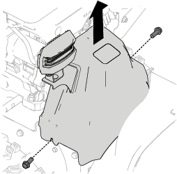
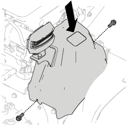
Removing the Belt Cover
Removing the Traction Belt
Note: Complete this procedure if the traction belt is damaged.
-
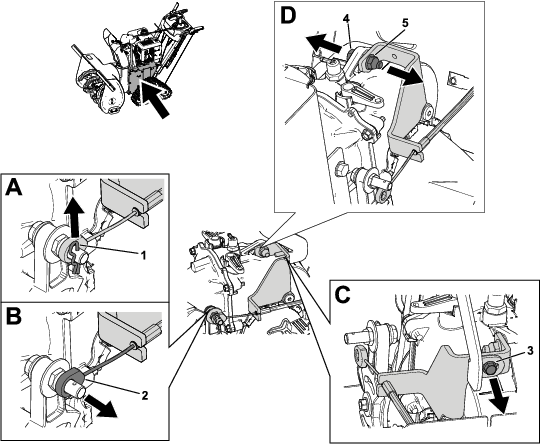
Remove the 2 screws (M8 x 1–1/4 x 20) securing the belt guide to the engine. Remove the belt guide.
-
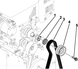
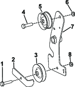
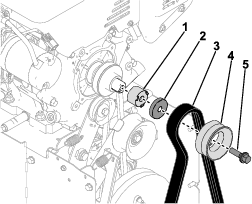
Remove the blade bolt (7/16 x 1–3/4 inch) securing the impeller pulley to the crankshaft. Remove the pulley, auger belt, pulley support, and spacer pulley from the crackshaft (Figure 7).
Note: If necessary, hold the hub between the pulley and the engine to keep the crankshaft from turning.
-
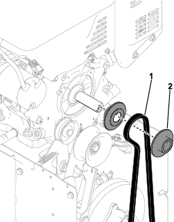
Remove the 2 traction pulleys and traction belt from the crankshaft (Figure 8).
-
From the underside of the machine, remove and discard the traction belt.
Removing the Traction Idler Arm
-
Remove and discard the extension spring on the traction idler arm.
-
Remove the Z-bend of the traction cable from the traction idler arm.
-
Remove the nut (7/16 inch) and shoulder bolt (7/16 x 1–3/4 inch) securing the traction idler arm to the brake clutch bracket (Figure 9).
-
Remove the nut (3/8 inch) and bolt (3/8 x 1–3/8 inch) securing the idler pulley to the traction idler arm. Discard the traction idler arm and idler pulley.
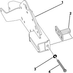
Removing the Hydrostatic Drive Support
-
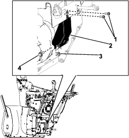
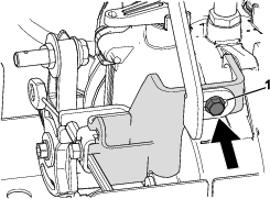
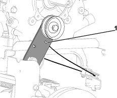
From the back of the machine, remove the 2 screws (1/4 x 5/8 inch) securing the hydrostatic drive support to the top plate (Figure 10).
-
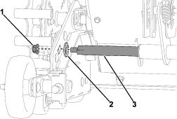
Remove the bolt (5/16 x 1–1/4 inch) and locknut (5/16 inch) securing the bottom of the hydrostatic drive support to the hydrostatic drive assembly. Remove the hydrostatic drive support from the machine (Figure 10).
-
Discard the hydrostatic drive support and 5 clips (1/4 inch).
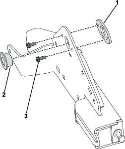
Removing the Hydrostatic Drive Bracket
-
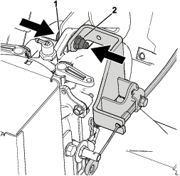
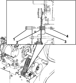
Remove the hairpin and hydrostatic drive cable from the bolt on the hydrostatic drive assembly. Remove the hydrostatic drive cable from the bolt (Figure 11).
-
Remove the screw (1/4 x 5/8 inch) securing the hydrostatic drive bracket to the upper hydrostatic drive bracket (Figure 11).
-
Remove the bolt (5/16 x 1–1/4 inch) and locknut (5/16 inch) securing the hydrostatic drive bracket to the hydrostatic drive assembly (Figure 11).
-
Remove the hydrostatic drive bracket with the hydrostatic drive cable still attached to the bracket.
-
Remove the retaining ring securing the hydrostatic drive cable to the bracket.
-
Remove the hydrostatic drive cable from the bracket and discard the bracket.
Installing the Hydrostatic Drive Bracket
Parts needed for this procedure:
| Hydrostatic drive bracket | 1 |
| Retaining ring | 1 |
| Cable clamp | 1 |
| Tapered hex bolt (1/4 x 5/8 inch) | 1 |
-
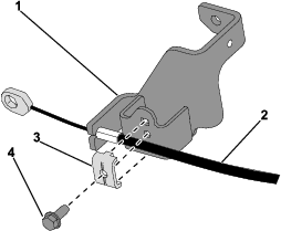
Install the hydrostatic drive cable to the new hydrostatic drive bracket.
-
Install the hydrostatic drive cable to the hydrostatic drive bracket, secure with a retaining ring.
-
Install the new cable clamp to the hydrostatic drive bracket, secure with the tapered hex bolt (1/4 x 5/8 inch) (Figure 12).
-
-
Install the hydrostatic drive bracket to the hydrostatic drive assembly.
-
Install the hex bolt (1/4 x 5/8 inch) securing the hydrostatic drive bracket to the upper hydrostatic drive bracket (Figure 13).
Note: Install the screw finger tight.
-
Install the hydrostatic drive cable to the bolt on the hydrostatic drive assembly, secure with the hairpin (Figure 14).
Installing the Hydrostatic Drive Support
Parts needed for this procedure:
| Hydrostatic drive support | 1 |
| Clip (1/4) | 5 |
| Bolt (5/16 x 1–1/4 inch) | 1 |
| Locknut (5/16 inch) | 1 |
-
Install the 5 clips (1/4 inch) to the new hydrostatic drive support.
-
Install the new hydrostatic drive support to the hydrostatic drive assembly.
-
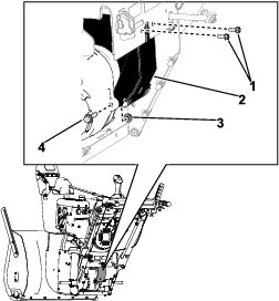
Secure the top of the hydrostatic drive support to the hydrostatic drive assembly and hydrostatic drive bracket with the new bolt (5/16 x 1–1/4 inch) and locknut (5/16 inch) (Figure 15).
-
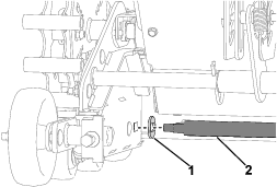
Secure the bottom of the hydrostatic drive support to the hydro with the retained bolt (5/16 x 1–1/4 inch) and locknut (5/16 inch) (Figure 16).
-
-
Install the 2 screws (1/4 x 5/8 inch) securing the hydrostatic drive support to the top plate (Figure 16).
-
Tighten the screw (1/4 x 5/8 inch) securing the hydrostatic drive bracket to the upper hydrostatic drive bracket (Figure 13).
Installing the Traction Clutch Arm Assembly
Parts needed for this procedure:
| Traction clutch arm | 1 |
| Extension spring | 1 |
| Traction belt | 1 |
| Flat idler pulley | 1 |
| V-idler pulley | 1 |
| Belt guide | 1 |
| Bolt (5/16 x 1-1/2 inches) | 1 |
| Locknut (5/16 inch) | 1 |
-
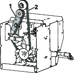
Install the new idler pulleys, traction belt, and belt guide to the new traction clutch arm.
-
Install the flat idler pulley to the top of the traction clutch arm, secure with the bolt (3/8 x 1-3/8 inches) and locknut (3/8 inch) (Figure 17).
Note: Install the fasteners finger tight and then secure with a wrench.
-
Install the V–idler pulley, traction belt, and belt guide to the bottom of the traction clutch arm, secure with the new bolt (5/16 x 1-1/2 inches) and locknut (5/16 inch) (Figure 17).
Note: Install the fasteners finger tight and then secure with a wrench.
-
-
Apply anti-seize to the pivot area of the traction clutch arm.
-
Install the shoulder bolt (7/16 x 1-3/4 inches) into the pivot area of the traction clutch arm.
-
Install the Z-bend of the traction cable to the traction clutch arm (Figure 18).
-
Install the traction clutch arm assembly to the brake clutch bracket, secure with the new shoulder bolt (7/16 x 1-3/4 inches) and locknut (7/16 inch) (Figure 19).
-
Install the extension spring to the traction clutch arm and extend the spring to the right side plate.
-
If reusing the traction belt, route the traction belt as shown below (Figure 20).
Installing the Traction Belt
Note: Complete the this procedure if replacing the traction belt.
-
Install the traction belt onto the hydrostatic drive assembly and pulleys on crankshaft.
-
Route the traction belt around the hydrostatic drive assembly (Figure 20).
-
Install the 2 traction pulleys onto the crankshaft and route the traction belt between the pulleys (Figure 20).
-
-
Install the spacer pulley, pulley support, impeller pulley, and auger belt to the crank shaft (Figure 22).
-
Apply Loctite to the blade bolt (7/16 x 1–3/4 inch) threads.
-
Install the blade bolt (7/16 x 1–3/4 inch) to the impeller pulley (Figure 22). Torque the bolt to 13.6–18.1 N•m (120–163 in-lb).
-
Apply Loctite to the 2 screw (M8 x 1–1/4 x 20) threads.
-
Install the belt guide to the engine, secure with the 2 screws (M8 x 1–1/4 x 20).
-
Check for proper clearance between the auger belt and belt guide. There should be a ~3.2 mm (1/8 inch) gap.
Installing the Belt Cover
-
Install the belt cover to the machine, secure with the 2 screws (1/4 x 5/8 inch) (Figure 23).
-
Connect the harness to the light assembly.
Installing the Rear and Bottom Cover
Parts needed for this procedure:
| Bottom cover | 1 |
-
From the underside of the machine, install the new bottom cover, secure with the 4 screws (1/4 x 5/8 inch).
-
Bring the rear cover to the machine, hook the left clutch cable spring to the hydrostatic drive assembly. Repeat with the right clutch cable.
-
Route the hydrostatic drive cable through the rear cover.
-
Install the rear cover to the frame plate, secure with 6 screws (1/4 x 5/8 inch).
-
Install the hydrostatic drive cable to the speed selector bracket (Figure 24).
-
Secure the hydrostatic drive cable to the speed selector with a shoulder bolt (1/4 x 1 inch), stepped washer, and nut (1/4 inch) (Figure 24).
Note: The flat side of the stepped washer should be on the speed selector.

-
From the left side of the machine, hook the clutch cable to the clutch lever (Figure 25). Repeat on the right side.
-
From the left side of the machine, install the cable clamp to the lower handle tube, secure with the bolt (1/4 x 2–3/4 inch) and nut (1/4 inch) (Figure 25). Repeat on the right side.
-
Install the height adjuster bracket to the top plate and rear cover, secure with the 3 screws (1/4 x 5/8 inch) (Figure 26).
-
Install the new bottom cover to the bottom of the machine, secure with the 4 screws (1/4 x 5/8 inch).
-
Remove the jack stands from under the left and right hydrostatic drive shafts. Replace the jack stands or overhead lifting device used in Preparing the Machine.
Assembling the Snow Tracks
Parts needed for this procedure:
| Left track support assembly | 1 |
| Right track support assembly | 1 |
| Pivot bar plate | 2 |
| Carriage bolt (5/16 x 1 inch) | 6 |
| Locknut (5/16 inch) | 11 |
| Support plate | 2 |
Note: Start the procedures on the left track support and then repeat on the right track support.
-
Install the tensioner to the new track support assembly, loosely secure with the retained washer (3/8 inch) and screw (3/8 x 4 inch) (Figure 27).
-
Install the axle bushing into the track support (Figure 28).
-
Install the axle bushing support to the track support, secure with the 2 screws (1/4 x 5/8 inch) (Figure 28).
-
Install the new pivot bar plate to the track support, secure with 2 new carriage bolts (5/16 x 1 inch) and 2 locknuts (5/16 inch) (Figure 29).
-
Install the new support plate to the track support, secure with the new carriage bolt (5/16 x 1 inch) and locknut (5/16 inch) (Figure 29).
-
Install the retained bogey yoke to the track support, loosely secure with the carriage bolt (3/8 x 3 inch) and locknut (3/8 inch) (Figure 30).
-
Install the retained right bogey wheel to the bogey yoke and track support, loosely secure with the carriage bolt (3/8 x 3 inch), tensioner bushing, and locknut (3/8 inch) (Figure 30).
-
Install the left bogey wheel to the track support, secure with the carriage bolt (3/8 x 3 inch), tensioner bushing, and locknut (3/8 inch) (Figure 30).
Installing the Snow Tracks
Parts needed for this procedure:
| Pivot bar | 2 |
| Special washer | 4 |
| Locknut (3/8 inch) | 4 |
| Wheel support assembly | 2 |
| Carriage bolt (5/16 x 3/4 inch) | 4 |
| Bogey wheel | 4 |
| Shoulder bolt (3/8 x 2–7/16 inch) | 4 |
| Locknut (3/8 inch) | 4 |
-
From the left side of the machine, install the drive wheel assembly to the axle hub, secure with the lynch pin. Repeat on the right side.
-
Place the left and right track assemblies on their respective sides of the machine.
-
Slide the new pivot bar into the pivot hub, secure with 2 hairpins.
-
Install the 2 special washers on the pivot bar in the pivot hub. Install the pivot bar with the special washers to the track assemblies and pivot plate, secure with 2 new locknuts (3/8 inch) (Figure 31).
-
Install the 2 special washers on the new pivot bar. Install the new pivot bar with special washers through the track assemblies and support plate, secure with 2 new locknuts (3/8 inch) (Figure 32).
-
From the left side of the machine, slide the bogey yoke to the left and install the track around the track assembly and drive wheel. Repeat on the right side.
-
From the left side of the machine, tighten the tensioner until there is 9.5 mm (3/8 inch) track deflection. Repeat on the right side.
-
From the left side of the machine, torque the 2 nuts (9/16 inch) securing the bogey yoke to the track assembly to 47.5 N•m (35 ft-lb). Repeat on the right side.
-
Install the new wheel support assembly to the track support, secure with 2 new carriage bolts (5/16 x 3/4 inch) and 2 locknuts (5/16 inch).
-
Install the 2 new bogey wheels onto the wheel support assembly, secure with 2 new shoulder bolts (3/8 x 2–7/16 inch) and 2 locknuts (3/8 inch).
Adjusting the Clutch Cables
Test the machine for proper operation. If necessary, adjust the clutch cables; refer to the product’s Operator’s Manual.