| Maintenance Service Interval | Maintenance Procedure |
|---|---|
| Before each use or daily |
|
Introduction
This machine is intended to be used by professional, hired operators in commercial applications. It is designed primarily for grooming on well-maintained athletic infields and on commercial grounds. Using this product for purposes other than its intended use could prove dangerous to you and bystanders.
This machine is not intended to be used without a Toro-approved mid-mount attachment installed; do not operate this machine without a mid-mount attachment installed.
Read this information carefully to learn how to operate and maintain your product properly and to avoid injury and product damage. You are responsible for operating the product properly and safely.
Visit www.Toro.com for product safety and operation training materials, accessory information, help finding a dealer, or to register your product.
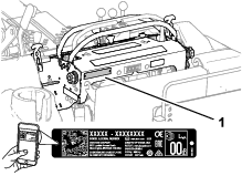
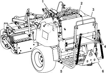
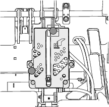
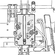
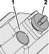
Whenever you need service, genuine Toro parts, or additional information, contact an Authorized Service Dealer or Toro Customer Service and have the model and serial numbers of your product ready. Figure 1 identifies the location of the model and serial numbers on the product. Write the numbers in the space provided.
Important: With your mobile device, you can scan the QR code (if equipped) on the serial number plate to access warranty, parts, and other product information.
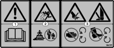
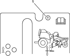
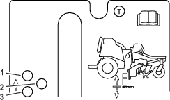
This manual identifies potential hazards and has safety messages identified by the safety-alert symbol (Figure 2), which signals a hazard that may cause serious injury or death if you do not follow the recommended precautions.

This manual uses 2 words to highlight information. Important calls attention to special mechanical information and Note emphasizes general information worthy of special attention.
Warning
CALIFORNIA
Proposition 65 Warning
The engine exhaust from this product contains chemicals known to the State of California to cause cancer, birth defects, or other reproductive harm.
Battery posts, terminals, and related accessories contain lead and lead compounds, chemicals known to the State of California to cause cancer and reproductive harm. Wash hands after handling.
Use of this product may cause exposure to chemicals known to the State of California to cause cancer, birth defects, or other reproductive harm.
Safety
This machine has been designed in accordance with ANSI B71.4-2017 and complies with this standard when a Toro-approved mid-mount attachment is installed; do not operate this machine without a mid-mount attachment installed.
General Safety
This product is capable of causing personal injury. Always follow all safety instructions to avoid serious personal injury.
-
Read and understand the contents of this Operator’s Manual before starting the engine.
-
Do not put your hands or feet near moving components of the machine.
-
Do not operate the machine without all guards and other safety protective devices in place and functioning properly on the machine.
-
Use your full attention while operating the machine. Do not engage in any activity that causes distractions; otherwise, injury or property damage may occur.
-
Keep bystanders and children out of the operating area. Do not allow children to operate the machine. Allow only people who are responsible, trained, familiar with the instructions, and physically capable to operate the machine.
-
Stop the machine, shut off the engine, and remove the ignition key before servicing or fueling the machine.
Improperly using or maintaining this machine can result in injury.
To reduce the potential for injury, comply with these safety instructions
and always pay attention to the safety-alert symbol  , which means
Caution, Warning, or Danger—personal safety instruction. Failure
to comply with these instructions may result in personal injury or
death.
, which means
Caution, Warning, or Danger—personal safety instruction. Failure
to comply with these instructions may result in personal injury or
death.
You can find additional safety information where needed throughout this manual.
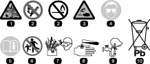
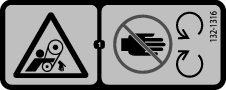
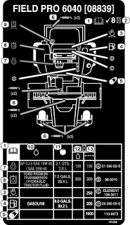
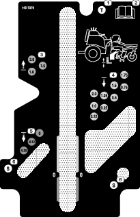
Safety and Instructional Decals
|
Safety decals and instructions are easily visible to the operator and are located near any area of potential danger. Replace any decal that is damaged or missing. |


Setup
Installing a Mid-Mount Attachment
Parts needed for this procedure:
| Mid-mount attachment (ordered separately; refer to your authorized Toro distributor) | 1 |
Install a Toro-approved mid-mount attachment; refer to the mid-mount attachment Installation Instructions.
Preparing the Machine
-
Remove the machine from the crate, park the machine on a level surface or move the machine to a machine lift.
-
Engage the parking brake.
-
Lower the mid-mount attachment.
-
Shut off the engine and remove the key.
-
Wait for all moving parts to stop and allow the engine to cool.
-
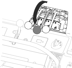
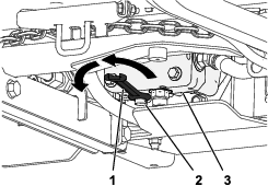
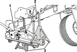
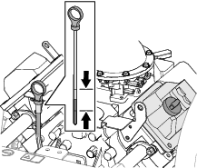
Move the mid-mount attachment control forward and backward to relieve hydraulic pressure (Figure 3).
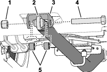
Installing the Rear Attachment Lift Frame
Parts needed for this procedure:
| Short drawbar chain (17-1/2 inches) | 2 |
| Lift bracket | 1 |
| Carriage bolt (5/16 x 1 inch) | 6 |
| Washer (3/8 x 7/8 inch) | 4 |
| Flange locknut (5/16 inch) | 6 |
| Rear attachment lift frame assembly | 1 |
| Long rear-lift chain (25 inches) | 2 |
| Shackle | 2 |
| Clevis pin | 2 |
| Cotter pin | 2 |
| Flange-head bolt (3/8 x 1-3/4 inches) | 2 |
| Washer (2/5 inch) | 2 |
| Flange locknut (3/8 inch) | 3 |
| Chain sleeve | 2 |
| Flange-head bolt (1/2 x 3 inches) | 6 |
| Flange locknut (1/2 inch) | 6 |
| Capscrew (3/4 x 4-1/2 inches) | 1 |
| Locknut (3/4 inch) | 1 |
| Flange-head bolt (3/8 x 1-1/2 inches) | 1 |
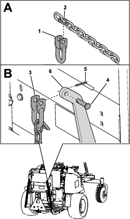
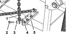
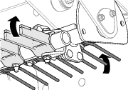
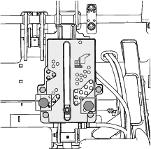
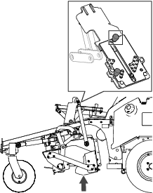
Assembling the Drawbar Chains to the Machine
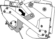
-
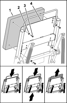
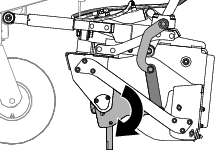
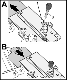
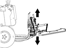
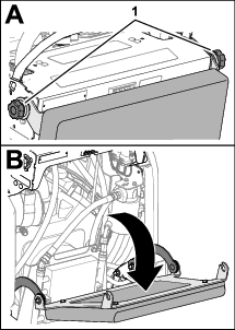
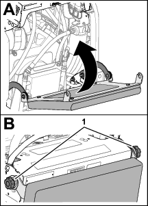
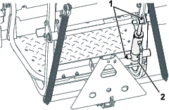
Raise the operator’s platform (Figure 4).
Note: The operator’s platform does not stay in the upright position; restrain the platform or hold it in place while completing this procedure.
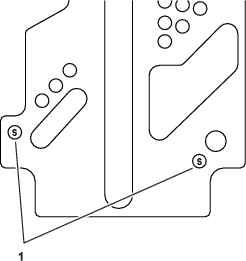
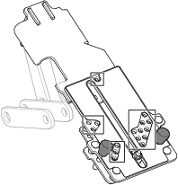
-
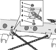
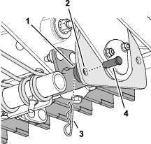
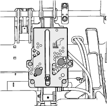
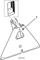
Align the link at the end of a short drawbar chain to the hole in the chain tab of the rear frame plate (Figure 5).
Ensure the link is flush to the chain tab and the next link aligns into the groove in the tab.
-
Assemble the chain to the chain tab with a carriage bolt (5/16 x 1 inch), washer (3/8 x 7/8 inch), and flange locknut (5/16 inch) as shown in Figure 5.
-
Torque the locknut to 19.8 to 25.4 N∙m (175 to 225 in-lb).
-
Repeat steps 2 through 4 for the other short drawbar chain at the chain tab at the other side of the machine.
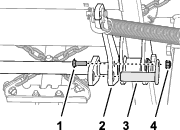
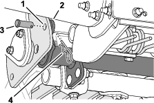
Preparing the Rear Attachment Adapter and Drawbar
-
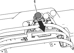
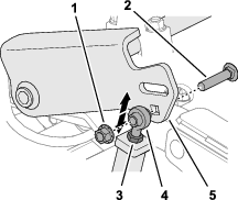
Install the lift bracket to the rear frame assembly as shown in Figure 6.
-
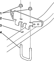
Install the tow-stop bracket to the drawbar with a U-bolt and 2 flange locknuts (5/16 inch) as shown in Figure 11.
Note: Install the bracket with the tabs facing the front of the machine.
-
Connect the rear attachment adapter assembly to the drawbar with a hex-head bolt (3/4 x 3-1/2 inches), flat washer, and a locknut (3/4 inch) as shown in Figure 8.
Note: Install the screw through the rearmost hole in the adapter assembly and drawbar.
-
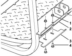
Install the lift chains to the lift-bar assembly with flange-head bolts (3/8 x 1-3/4 inches), washers (3/8 inch), and locknuts (3/8 inch).
-
Slide the chain sleeves onto the lift chains, and then install the lift chains to the shaft-lift assembly with shackles, clevis pins, and cotter pins.
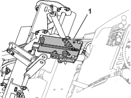
Assembling the Lift Frame to the Machine
-
Connect the second link of the long rear-lift chains to the top of the lift frame using shackles, clevis pins, and cotter pins (Figure 9).
-
Connect the bottom of the long rear-lift chains to the hanger tube at the bottom of the lift frame using flange-head bolts (3/8 x 1-3/4 inches), washers (2/5 inch), and flange locknuts (3/8 inches) as shown in Figure 10.
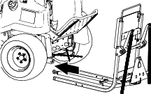
-
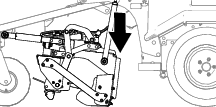
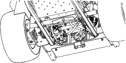
Align the rear attachment lift frame under the machine (Figure 11).
Note: Ensure that the rear attachment lift frame is centered under the machine.
-
Lift the back of the rear attachment lift frame to align the holes in the lift-frame tubes with the holes in the channels of the rear frame (Figure 12).
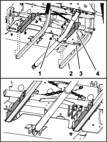
Note: Install the hardware with the bolt heads toward the outside of the machine.
-
Assemble the 6 flange-head bolts (1/2 x 3 inches) through the holes in the channels and the tubes.
-
Assemble the 6 flange locknuts (1/2 inch) onto the flange-head bolts.
-
Torque the flange-head bolts and locknuts to 91 to 113 N∙m (67 to 83 ft-lb).
-
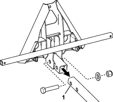
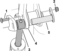
Align the hole in the rod end of the drawbar with the holes in the drawbar mount of the rear-frame bulkhead (Figure 13).
-
Assemble the rod end to the mount with the capscrew (3/4 x 4-1/2 inches), 2 spacer, and locknut (3/4 inch) as shown in Figure 13.
-
Torque the capscrew and locknut to 320 to 396 N∙m (238 to 392 ft-lb).
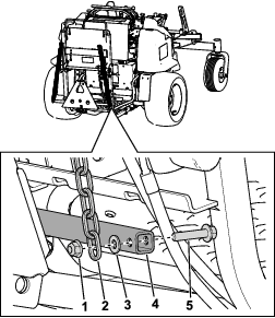
Assembling the Drawbar Chains to the Lift Frame
-
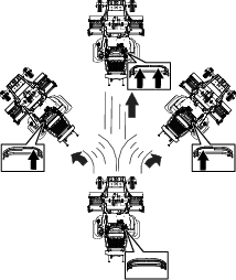
Cross the attached chains from the (Figure 14) over the drawbar.
-
Pull the slack from the chain and align the link to the hole in the tow-stop bracket of the of the drawbar.
Ensure the link is flush to the outboard side of the bracket, and the next link forward aligns into the groove in the bracket.
-
Assemble the chain to the stop bracket with a flange-head bolt (5/16 x 1 inch), washer (3/8 x 7/8 inch), and flange locknut (5/16 inch) as shown in Figure 14.
-
Repeat steps 1 through 3 for the other chain at the other side of the stop bracket.
-
Where the chains cross (Figure 15), assemble them with a flange-head bolt (3/8 x 1-1/2 inches) and flange locknut (3/8 inch).
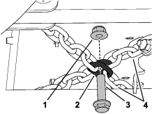
-
Torque the 5/16 inch flange-head bolts and locknuts to 19.8 to 25.4 N∙m (175 to 225 in-lb).
-
Torque the 3/8 flange-head bolt and locknut to 37 to 45 N∙m (27 to 33 ft-lb).
Assembling the Rear Attachment Lift Cylinder
-
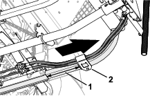
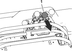
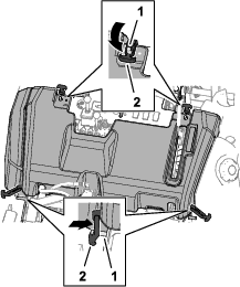
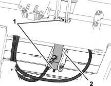
Remove the cable tie that secures the rear hydraulic cylinder and hoses to the back of the machine.
-
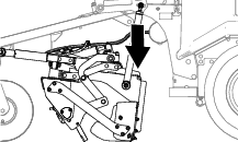
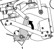
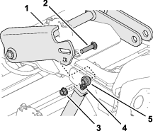
Remove the carriage bolt and flange locknut that secures the cylinder pin to the lift-shaft arm (Figure 16).
-
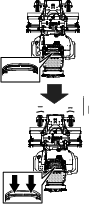
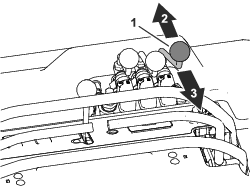
Route the cylinder and hoses to the back of the lift frame (Figure 17).
-
Install the hose guard around the hoses 9 cm (3.5 inches) from the rear tube channel as shown in Figure 17.
Important: Ensure that the extend and retract hoses are not twisted around each other.If the hoses are twisted, loosen the hoses at the bulkhead side and alleviate hose twist, then torque them again.
-
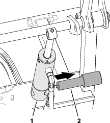
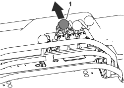
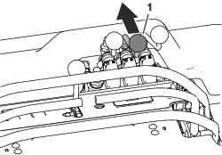
Assemble the rear attachment lift cylinder onto the mount shaft of the rear frame (Figure 18).
-
Align the rod end of the cylinder between the lift-shaft arms (Figure 19).
-
Secure the rod end to the lift-shaft arms with the cylinder pin, carriage bolt, and flange locknut.
-
Grease the attachment-lift cylinder before first operation; refer to Greasing the Bearings and Bushings.
-
Lower the operator’s platform.
Note: When the rear attachment-lift cylinder is fully extended, the drawbar should be fully raised against the rubber bumper.
Product Overview
Engine and Attachment Controls
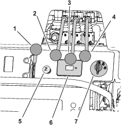
Throttle Lever
Use the throttle lever (Figure 22) to control the engine speed.
Rear Attachment Lift Control
Use the rear attachment lift control to raise or lower an optional rear installed attachment.
Mid-Mount Attachment Tilt Control
Use the mid-mount attachment tilt control to adjust the engagement angle of the mid-mount attachment.
Mid-Mount Attachment Lift Control
Use the mid-mount attachment lift control to raise or lower the mid-mount attachment.
Choke Control
Use the choke control (Figure 22) to adjust the choke position for cold-engine starting.
Hour Meter/Controller
The hour meter and controller (Figure 22) preforms the following functions:
-
Displays the total hours of engine operation.
-
Provides control for the safety interlock system and displays indicators for the following components:
-
Parking brake is in the ENGAGED position.
-
Motion controls are in the NEUTRAL position.
-
Operator is standing on the operator’s platform.
-
-
Indicates the voltage and low charging-system operation.
Ignition Key and Switch
Use the ignition switch to start and hut off the engine.
Parking Brake and Motion Control
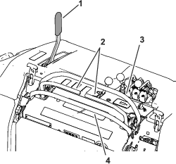
Parking-Brake Handle
Use the parking brake handle (Figure 23) to engage and disengage the parking brake.
The parking-brake handle is located on the control tower, to the left of the front reference bar.
Motion-control bars
The motion-control levers (Figure 23) are located at each side of the top control tower, and control the forward and reverse motion of the machine
Move the levers forward or backward to control the drive wheel on the same side forward or reverse respectively. The wheel speed is proportional to the amount you move the lever.
|
Length |
292.3 cm (115 inches) |
|
Width (without mid-mount attachment installed) |
147.3 cm (58 inches) |
|
Width (with multi–tool attachment installed) |
172.7 cm (68 inches) |
|
Height |
129.5 cm (51 inches) |
|
Net weight (empty with no options installed) |
521.6 kg (1,150 lbs) |
|
Net weight (with multi–tool attachment installed) |
734.8 kg (1,620 lbs) |
|
Maximum forward speed |
16 km/h (10 mph) |
|
Maximum reverse speed |
8 km/h (5 mph) |
Operation
Before Operation
Before Operation Safety
General Safety
-
Never allow children or untrained people to operate or service the machine. Local regulations may restrict the age of the operator. The owner is responsible for training all operators and mechanics.
-
Become familiar with the safe operation of the equipment, operator controls, and safety signs.
-
Park the machine on a level surface; engage the parking brake, lower the attachments to the ground, shut off the engine, remove the key, and wait for all movement to stop before leaving the machine.
-
Know how to stop the machine and engine quickly.
-
Check that any installed operator-presence controls, safety switches, and shields are attached and functioning properly. Do not operate the machine unless they are functioning properly.
-
Before operating, always inspect the machine to ensure that the components and hardware are in good working condition. Replace worn or damaged components and hardware.
Fuel Safety
-
Fuel is extremely flammable and highly explosive. A fire or explosion from fuel can burn you and others and can damage property.
-
To prevent a static charge from igniting the fuel, place the container and/or machine directly on the ground before filling, not in a vehicle or on an object.
-
Fill the fuel tank outdoors, in an open area, when the engine is cold. Wipe up any fuel that spills.
-
Do not handle fuel when smoking or around an open flame or sparks.
-
Do not remove the fuel cap or add fuel to the tank while the engine is running or hot.
-
If you spill fuel, do not attempt to start the engine. Avoid creating a source of ignition until the fuel vapors have dissipated.
-
Store fuel in an approved container and keep it out of the reach of children.
-
-
Fuel is harmful or fatal if swallowed. Long-term exposure to vapors can cause serious injury and illness.
-
Avoid prolonged breathing of vapors.
-
Keep your hands and face away from the nozzle and the fuel-tank opening.
-
Keep fuel away from your eyes and skin.
-
-
Do not store the machine or fuel container where there is an open flame, spark, or pilot light, such as on a water heater or on other appliances.
-
Do not fill containers inside a vehicle or on a truck or trailer bed with a plastic liner. Always place containers on the ground, away from your vehicle before filling.
-
Remove the equipment from the truck or trailer and refuel it while it is on the ground. If this is not possible, then refuel from a portable container rather than a fuel-dispenser nozzle.
-
Do not operate the machine without the entire exhaust system in place and in proper working condition.
-
Keep the fuel-dispenser nozzle in contact with the rim of the fuel tank or container opening at all times until fueling is complete. Do not use a nozzle lock-open device.
-
If you spill fuel on your clothing, change your clothing immediately. Wipe up any fuel that spills.
-
Never overfill the fuel tank. Replace the fuel cap and tighten it securely.
Fueling the Machine
Fuel Specification
| Petroleum fuel | Use unleaded gasoline with an octane rating of 87 or higher ((R+M)/2 rating method). |
| Ethanol blended fuel | Use an unleaded-gasoline blend with up to 10% ethanol (gasohol) or 15% MTBE (methyl tertiary butyl ether) by volume is acceptable. Ethanol and MTBE are not the same. |
| Gasoline with 15% ethanol (E15) by volume is not approved for use. Never use gasoline that contains more than 10% ethanol by volume, such as E15 (contains 15% ethanol), E20 (contains 20% ethanol), or E85 (contains up to 85% ethanol). Using unapproved gasoline may cause performance problems and/or engine damage which may not be covered under warranty. |
Important: For best results, use only clean, fresh fuel (less than 30 days old).
-
Do not use gasoline containing methanol.
-
Do not store fuel either in the fuel tank or fuel containers over the winter unless you use a fuel stabilizer.
-
Do not add oil to gasoline.
Using Stabilizer/Conditioner
Always use fuel stabilizer/conditioner in the machine to keep the fuel fresh longer.
Important: Do not use fuel additives containing methanol or ethanol.
Add the amount of fuel stabilizer/conditioner to fresh fuel as directed by the fuel-stabilizer manufacturer.
Filling the Fuel Tank
Fuel Tank Capacity: 31.4 L (8.3 US gal)
-
Park the machine on a level surface, engage the parking brake, shut off the engine, and remove the key.
-
Clean around the fuel-tank cap, and remove it.
-
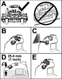
Fill the fuel tank to 25 mm (1 inch) below the filler neck.
Note: Do not fill the fuel tank completely full. The empty space in the tank allows the fuel to expand.
-
Assemble the fuel-tank cap to the filler neck of the tank.
Before Operations Checks
Perform the following daily procedures before operating the machine:
Checking the Safety-Interlock System
Checking the Parking Brake-Interlock Switches
-
Stand on the operator’s platform.
-
Disengage the parking brake.
-
Move the motion-control bars to the NEUTRAL position.
-
Try starting the engine.
Important: The engine should not start.If the engine starts, shut off the engine, remove the key, and contact you authorized Toro distributor for service.
Checking the Motion Control-Interlock Switches
-
Stand on the operator’s platform.
-
Engage the parking brake.
-
Move the left motion-control bar to the FORWARD position.
-
Try starting the engine.
-
Move the right motion-control bar to the FORWARD position.
-
Try starting the engine.
Important: The engine should not start.If the engine starts, shut off the engine, remove the key, and contact you authorized Toro distributor for service.
Checking the Operators Platform-Interlock Switches
Important: The operators platform-interlock switches are included with some attachment kits; they are not included on the base machine.
-
Engage the parking brake.
-
Move the motion-control bars to the NEUTRAL position.
-
Step off the operator’s platform, and stand on the ground.
-
Try starting the engine.
Important: The engine should not start.If the engine starts, shut off the engine, remove the key, and contact you authorized Toro distributor for service.
Adjusting the Backrest Position
-
Remove the 4 bolts and 4 washers that secure the backrest pad to the mounting plate (Figure 25).
-
Raise or lower the backrest pad.
-
Align the hole in the backrest pad with the holes in the mounting plate.
-
Secure the pad to the plate with the 4 bolts and 4 washers.
During Operation
During Operation Safety
General Safety
-
The owner/operator can prevent and is responsible for accidents that may cause personal injury or property damage.
-
Wear appropriate clothing, including eye protection; long pants; substantial, slip-resistant footwear; and hearing protection. Tie back long hair and do not wear loose clothing or loose jewelry.
-
Use your full attention while operating the machine. Do not engage in any activity that causes distractions; otherwise, injury or property damage may occur.
-
Do not operate the machine while ill, tired, or under the influence of alcohol or drugs.
-
Never carry passengers on the machine and keep bystanders and pets away from the machine during operation.
-
Operate the machine only in good visibility and appropriate weather conditions. Do not operate the machine when there is the risk of lightning.
-
Operate the machine only in good visibility to avoid holes or hidden hazards.
-
Before you start the engine, ensure that all drives are in neutral, the parking brake is engaged, and you are in the operating position.
-
Look behind and down before backing up to be sure of a clear path.
-
Use extreme care when approaching blind corners, shrubs, trees, or other objects that may block your view.
-
Stop the machine and inspect the attachment after striking an object or if there is an abnormal vibration in the machine. Make all necessary repairs before resuming operation.
-
Slow down and use caution when making turns and crossing roads and sidewalks with the machine. Always yield the right-of-way.
-
Operate the engine only in well-ventilated areas. Exhaust gases contain carbon monoxide, which is lethal if inhaled.
-
Never leave a running machine unattended.
-
Before leaving the operating position, do the following:
-
Park the machine on level ground.
-
Lower the attachments.
-
Engage the parking brake.
-
Shut off the engine and remove the ignition key.
-
Wait for all moving parts to stop.
-
-
Do not operate the machine when there is the risk of lightning.
-
Do not use the machine as a towing vehicle without the Toro-approved hitch kit.
-
When necessary, wet surfaces prior to conditioning to minimize dust creation.
-
Use accessories, attachments, and replacement parts approved by The Toro® Company only.
Slope Safety
-
Establish your own procedures and rules for operating on slopes. These procedures must include surveying the site to determine which slopes are safe for machine operation. Always use common sense and good judgment when performing this survey.
-
Slopes are a major factor related to loss of control and rollover accidents, which can result in severe injury or death. The operator is responsible for safe slope operation. Operating the machine on any slope requires extra caution.
-
Slopes are a major factor related to loss-of-control and tip-over accidents, which can result in severe injury or death. Operating the machine on any slope requires extra caution.
-
Operate the machine at a lower speed when you are on a slope.
-
If you feel uneasy operating the machine on a slope, do not do it.
-
Watch for holes, ruts, bumps, rocks, or other hidden objects. Uneven terrain could overturn the machine. Tall grass can hide obstacles.
-
Choose a low ground speed so you will not have to stop or shift while on a slope.
-
A rollover can occur before the tires lose traction.
-
Avoid operating the machine on wet grass. Tires may lose traction; regardless if the brakes are available and functioning.
-
Avoid starting, stopping, or turning the machine on a slope.
-
Keep all movement on slopes slow and gradual. Do not suddenly change the speed or direction of the machine.
-
Do not operate the machine near drop-offs, ditches, embankments, or bodies of water. The machine could suddenly roll over if a wheel goes over the edge or the edge caves in. Establish a safety area between the machine and any hazard (2 machine widths).
Operating the Parking Brake
-
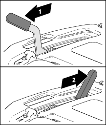
Pull the parking brake handle to engage the parking brake (Figure 26).
-
Push the parking brake handle to disengage the parking brake.
Starting the Engine
Important: Do not engage starter for more than 5 seconds at a time. If the engine fails to start, wait 15 seconds between attempts. Failure to follow these instructions can burn out the starter motor.
Note: You may need multiple attempts to start the engine the first time after adding fuel to an empty fuel system.
-
Move the motion-control bars to the NEUTRAL position.
-
Engage the parking brake.
-
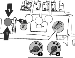
Move the throttle midway between the SLOW and FAST positions (Figure 27).
-
If the engine is cold, pull the choke control to the ON position (Figure 27).
Note: When operating the machine in temperatures less than 0°C (32°F) allow the engine time to warm up before using the machine. This prevents damage to the hydraulic system.
-
Rotate the ignition key to the START position (Figure 27).
Note: To prevent overheating the starter motor, do not engage the starter longer than 10 seconds. After continuous cranking the starter for 10 seconds, wait 60 seconds before engaging the starter motor again.
-
When the engine starts, rotate the key to the RUN position (Figure 27).
-
Move the throttle to the SLOW position, and allow the engine to warm.
-
As the engine warms up, push the choke control toward the OFF position (Figure 27).
Shutting Off the Engine
Important: Always remove the key and engage the parking brake when leaving the machine unattended.
-
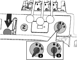
Move the motion-control bars to the NEUTRAL position.
-
Engage the parking brake.
-
Lower the attachments.
-
Move the throttle to the SLOW position (Figure 28).
-
Rotate the ignition key to the STOP position (Figure 28).
-
Remove the key and wait for all moving parts to stop before leaving the operator's position.
Driving the Machine
Caution
Machine can spin very rapidly by positioning 1 lever too much ahead of the other. You may lose control of the machine, which may cause damage to the machine or injury.
-
Use caution when making turns.
-
Slow the machine down before making sharp turns.
Driving Forward
Note: The engine shuts off if you move the motion-control bars with the parking brake engaged.
-
Move the motion-control bars to the NEUTRAL position.
-
Disengage the parking brake; refer to Operating the Parking Brake.
-
To drive the machine forward, perform the following:
Note: The machine moves faster the farther the motion-control levers are moved from the NEUTRAL position.
-
To move forward in a straight line, move both motion-control bars forward at the same time.
-
To turn left or right, pull the motion-control bar back toward neutral in the desired turn direction.
-
To stop the machine, move both motion-control bars to the NEUTRAL position.
-
Driving Backward
-
Move the motion-control bars to the NEUTRAL position.
-
Raise the mid-mount attachment and optional rear attachment.
-
To drive the machine backward, perform the following:
Note: The machine moves faster the farther the motion-control levers are moved from the NEUTRAL position.
-
To move backward in a straight line, move both motion-control bars backward at the same time.
-
To turn left or right, release pressure on the motion-control bar toward the desired turn direction.
-
To stop the machine, move both motion-control bars to the NEUTRAL position.
-
Adjusting the Height of the Mid-Mount Attachment
Raising the Mid-Mount Attachment
-
Park the machine on a level surface and engage the parking brake.
-
If you want to fully raise the mid-mount attachment remove the stop pin from the up-stop attachment-stop hole, and insert it into the stow attachment-stop hole; refer to Mid-Mount Attachment Stop.
-
With the engine running, pull back the mid-mount attachment lift control to raise the mid-mount attachment(Figure 31).
Lowering the Mid-Mount Attachment
-
Park the machine on a level surface.
-
If needed, adjust the mid-mount attachment stop depth; refer to Using the Attachment Stop During Operation.
-
With the engine running, push forward the mid-mount attachment lift control to lower the mid-mount attachment (Figure 32).
Adjusting the Tilt Angle of the Mid-Mount Attachment
Tilting the Mid-Mount Attachment Backward
Move the mid-mount attachment tilt control forward to rotate the tine-engagement angle backward.
Tilting the Mid-Mount Attachment Forward
Move the mid-mount attachment tilt control back to rotate the tine-engagement angle forward.
Selecting the Multi-Tool
-
Fully lift the multi-tool carrier; refer to Raising the Mid-Mount Attachment.
-
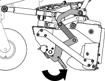
Rotate the multi-tool carrier backward until you can fully access the clevis pin and the 13 mm (1/2 inch) hole in the angle-select plate; refer to Tilting the Mid-Mount Attachment Forward.
-
Remove the hairpin and clevis pin that secures the multi-tool arm to the angle-select plate (Figure 36).
-
Repeat step 3 at the other side of the machine.
Caution
The multi-tool arm rotates freely when the clevis pins are removed; your hands or fingers could get pinched and injured if they are caught between the multi-tool arm and the angle-select plate.
-
Keep your hands and fingers clear of the area behind the angle-select plate while rotating the multi-tool.
-
Secure multi-tool arm from movement before removing the second clevis pin.
-
-
Rotate the multi-tool arm to select a set of plow tines (Figure 37).
-
Align the hole in the multi-tool arm with the hole in the angle-select plate (Figure 38).
-
Secure the multi-tool arm to the angle-select plate with the clevis pin and hair pin.
-
Repeat step 8 at the other side of the machine.
-
Adjust the tilt of the multi-tool carrier as needed (Figure 39).
Mid-Mount Attachment Stop
Attachment Stop Description
Use the stop pins and the mid-mount attachment stop to limit how far up or down you can position the mid-mount attachment, when transporting the machine, and when maintaining the mid-mount attachment.
You can use a combination of stop pin positions depending on your task.
| Task | Stop Pin 1 | Stop Pin 2 |
|---|---|---|
| Transporting the machine or maintaining the mid-mount attachment | Transport and maintenance position | Stow position |
| Limit the mid-mount attachment raised or lowered positions | Above grade position, grade position, or below grade position | Up-stop positions or stow position |
| Limit the mid-mount attachment lowered position | Above grade position, grade position, or below grade position | Stow position |
| Operate the mid-mount attachment with a full raise and lower range | Stow Position | Stow position |
Transport and Maintenance Stop-Pin Position
Insert a stop pin into the transport and maintenance position attachment-stop hole when you transport the machine between job sites, or when you adjust or maintain the mid-mount attachment. The transport and maintenance position lock the mid-mount attachment at the highest position.
Up-Stop Stop-Pin Positions
Insert a stop pin into an up-stop attachment-stop hole when you want to repeatability limit how high you can raise the mid-mount attachment. The up-stop position helps speed the process of raising or lowering the attachment at the end or beginning of each working pass.
Above-Grade Stop-Pin Positions
Insert a stop pin into an above-grade attachment-stop hole when you want to repeatability lower the mid-mount attachment to a selected above-grade position.
Grade- or Below-Grade Stop-Pin Positions
Insert a stop pin into a grade- or below-grade attachment-stop hole when you want to repeatability lower the mid-mount attachment to grade or a selected below-grade position.
Stow Stop-Pin Positions
Insert the stop pin(s) into the stow attachment-stop hole(s) when you are not using them.
Using the Attachment Stop During Operation
-
If needed, calibrate the mid-mount attachment stop to grade; refer to Calibrating Mid-Mount Attachment Stop.
-
Move the machine to a level surface at the job site, and engage the parking brake.
-
Lower the mid-mount attachmentAdjusting the Height of the Mid-Mount Attachment.
-
If used, insert a stop pin into the up-stop attachment-stop hole; refer to Up-Stop Stop-Pin Positions.
-
If used, raise the mid-mount attachment as needed and insert a stop pin into one of the following attachment-stop holes:
-
Raise or lower the mid-mount attachment until the attachment stop contacts the stop pin.
Using the Attachment Stop for Transporting or Maintenance
-
Move the machine to a level surface at the job site, and engage the parking brake.
-
If inserted remove the stop pin from the up-stop attachment-stop hole.
-
Fully raise the mid-mount attachment.
-
Insert a stop pin into the transport and maintenance position attachment-stop hole.
Calibrating Mid-Mount Attachment Stop
This procedure adjusts ground level reference point for the attachment stop.
Preparing the Machine
Optional Mid-Mount Grader
Operator supplied: 2 wood blocks 38 mm (1-1/2 inches) thick
-
Move the machine to a level surface and engage the parking brake.
-
If inserted remove the stop pins from the following mid-mount attachment stop positions:
-
Transport and maintenance position attachment-stop hole
-
Up-stop attachment-stop hole
-
Grade- or below-grade attachment-stop hole
-
Above-grade attachment-stop hole
-
-
Fully raise the mid-mount attachment; refer to Raising the Mid-Mount Attachment.
-
Tilt the multi-tool carrier backward (Figure 50) until the tines are aligned higher that the bottom of the grader blade; refer to Tilting the Mid-Mount Attachment Forward.
Positioning the Mid-Mount Attachment and Attachment Stop
-
Align a 38 mm (1.5 inches) wood block thick under each side of the mid-mount attachment.
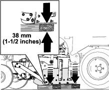
-
Lower the mid-mount attachment onto the wood blocks, shut off the engine, remove the key, and wait for all moving parts to stop.
-
Loosen the rod end jam nut that secures the rod end to the lift link (Figure 47).
-
Remove the carriage bolt and locknut that secures the lift link to the lift-arm bracket, and rotate the lift link rearward.
-
Repeat steps 3 and 4 at the other side of the machine.
-
Start the engine, and move the mid-mount attachment lift control rearward until the mid-mount attachment lift cylinder is fully extended.
-
Insert a stop pin into the 38 mm (1.5 inch) above-grade attachment-stop hole.
-
Move the mid-mount attachment lift control forward until the attachment stop contacts the stop pin.
-
Shut off the engine, remove the key, and wait for all moving parts to stop.
Adjusting the Lift Links
-
Align the lift link to the lift-arm bracket, and rotate the rod end until the hole in the rod end aligns with the hole in the lift-arm bracket.
-
Assemble the rod end to the lift-arm bracket with the carriage bolt and locknut.
-
Tighten the jam nuts securing the rod end to the lift link to 91 to 113 N⋅m (67 to 83 ft-lbs).
-
Repeat steps 1 through 3 at the other side of the machine.
-
Start the engine, raise the mid-mount attachment, remove the wood blocks, and remove the stop pin from the 38 mm (1.5 inch) above-grade attachment-stop hole.
-
Fully lower the mid-mount attachment to the ground.
-
Shut off the engine, remove the key, and wait for all moving parts to stop.
Raising and Lowering the Optional Rear Attachment
-
Move the machine to the job site, and engage the parking brake.
-
Use the rear attachment-lift control (Figure 56) to adjust the position of an optional rear attachment as follows:
-
Move the rear attachment lift control forward to lower the rear attachment.
-
Move the rear attachment lift control rearward to raise the rear attachment.
-
Operating Tips
Refer to the attachment Operator's Manual for specific operating instructions for any installed attachments.
Practice driving the machine; when operating the machine, consider the characteristics of ground speed and engine speed:
-
To transfer maximum power to the wheels, move the throttle control to the FAST and slightly press the traction controls forward.
-
Maintain constant engine speed by pressing the traction controls slowly; this allows the engine to keep up with the ground speed of the vehicle.
-
Pushing the traction controls too quickly reduces the engine speed; which can reduce the torque-power that moves the vehicle.
-
Alternatively, maximum ground speed is achieved when the throttle control is in the FAST position and the traction controls are slowly but fully pressed.
Note: If the attachment adapter becomes stuck to the traction unit adapter, insert a pry bar or a screwdriver into the pry slot to disengage the parts (Figure 57).
After Operation
After Operation Safety
-
Park the machine on a level surface; engage the parking brake; shut off the engine; remove the key; and wait for all movement to stop before leaving the machine.
-
Clean grass and debris from the muffler and engine compartment to help prevent fires. Clean up oil or fuel spills.
-
Allow the engine to cool before storing the machine in any enclosure.
-
Shut off the fuel before storing or transporting the machine.
-
Never store the machine or fuel container where there is an open flame, spark, or pilot light, such as on a water heater or on other appliances.
-
Keep all parts of the machine in good working condition and all hardware tightened.
-
Replace all worn or damaged decals.
Moving a Non-Functioning Machine
If you must tow or push the machine, open the bypass valves to bypass the hydraulic fluid.
Important: Do not move the machine without first opening the bypass valves on the hydraulic pumps, otherwise you could damage motor components.Do not move the machine faster than 4.8 km/h (3 mph); only move machines a very short distance. If you must move the machine more than a short distance, transport it on a trailer. If you exceed towing limits, severe damage to the hydraulic pumps may result.
Caution
The wheels can move freely when the bypass valves are opened. The machine can roll uncontrolled, possibly causing injury.
If you must tow the machine, move slowly and ensure that the machine does not collide with the towing vehicle.
-
Raise the mid-mount attachment and optional rear attachment.
-
Shut off the engine, remove the key, engage the parking brake, and chock the wheels.
-
Wait for all moving parts to stop and allow machine components to cool.
-
If attached, remove the optional rear attachment.
-
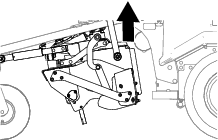
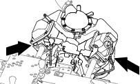
Access the bypass valves from under the rear of the machine.
-
With a 5/8 wrench, open the bypass valve on the bottom of the hydraulic pump by turning the valve approximately 2 full rotations as shown in .
-
Repeat step 6 to open the bypass valve on the bottom of the other hydraulic pump.
Note: The wheels can now spin freely.
Important: Do not rotate bypass valves more than 2 turns; this prevents the valves from falling out of the pump and ensures that hydraulic fluid does not spill.
-
Remove the chocks from the wheels, disengage the parking brake, and move the machine to the desired location.
-
After moving the machine and before starting the engine, close and tighten the bypass valves for operation:
Important: Do not start or run the engine when the bypass valves are set to the open position.
-
Shut off the engine, remove the key, engage the parking brake, and chock the wheels.
-
Wait for all moving parts to stop and allow machine components to cool.
-
Close, but do not tighten, the bypass valve by turning it approximately 2 full rotations until it stops.
-
Torque the bypass valve to 12.4 to 14.7 N⋅m (110 to 130 in-lb).
-
Repeat step 4 to close the bypass valve on the bottom of the other hydraulic pump.
-
Transporting the Machine
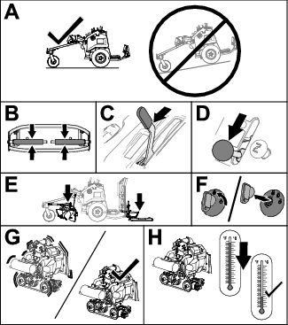
Use a heavy-duty trailer or truck to transport the machine. Use a full-width ramp. Ensure that the trailer or truck has all the necessary brakes, lighting, and marking as required by law. Please carefully read all the safety instructions. Knowing this information could help you or bystanders avoid injury. Refer to your local ordinances for trailer and tie-down requirements.
Warning
Driving on the street or roadway without turn signals, lights, reflective markings, or a slow-moving-vehicle emblem is dangerous and can lead to accidents, causing personal injury.
Do not drive the machine on a public street or roadway.
Selecting a Trailer
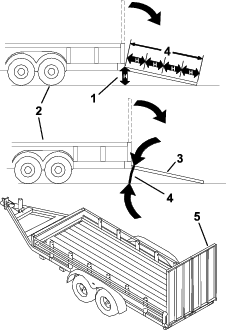
Warning
Loading a machine onto a trailer or truck increases the possibility of tip-over and could cause serious injury or death (Figure 59).
-
Use only a full-width ramp; do not use individual ramps for each side of the machine.
-
Ensure that the length of ramp is at least 4 times as long as the height of the trailer or truck bed to the ground.
Loading the Machine
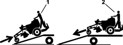
Warning
Loading a machine onto a trailer or truck increases the possibility of tip-over and could cause serious injury or death.
-
Use extreme caution when operating a machine on a ramp.
-
Back the machine up the ramp and walk it forward down the ramp.
-
Avoid sudden acceleration or deceleration while driving the machine on a ramp as this could cause a loss of control or a tip-over situation.
-
If using a trailer, connect it to the towing vehicle and connect the safety chains.
-
If applicable, connect the trailer brakes and lights.
-
Lower the ramp (Figure 59).
-
If installed, fully raise the mid-mount attachment and optional rear attachment.
-
Back the machine up the ramp (Figure 60).
-
Fully lower the mid-mount attachment and optional rear attachment.
-
Shut off the engine, remove the key, and engage the parking brake.
-
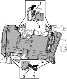
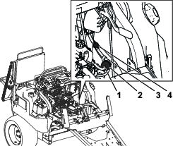
Tie down the machine at the front frame and the rear-attachment frame (Figure 61) with straps, chains, cable, or ropes.
Note: Refer to local regulations for tie-down requirements.
Maintenance
Note: Download a free copy of the electrical or hydraulic schematic by visiting www.Toro.com and searching for your machine from the Manuals link on the home page.
Maintenance Safety
-
Before adjusting, cleaning, repairing, or leaving the machine, do the following:
-
Park the machine on a level surface.
-
Move the throttle switch to the low-idle position.
-
Lower the attachment.
-
Ensure that the traction is in neutral.
-
Engage the parking brake.
-
Shut off the engine and remove the key.
-
Wait for all moving parts to stop.
-
Allow machine components to cool before performing maintenance.
-
-
If possible, do not perform maintenance while the engine is running. Keep away from moving parts.
-
Use jack stands to support the machine or components when required.
-
Carefully release pressure from components with stored energy.
Recommended Maintenance Schedule(s)
| Maintenance Service Interval | Maintenance Procedure |
|---|---|
| After the first 50 hours |
|
| Before each use or daily |
|
| After each use |
|
| Every 50 hours |
|
| Every 100 hours |
|
| Every 200 hours |
|
| Every 250 hours |
|
| Every 300 hours |
|
| Every 500 hours |
|
| Every 1,000 hours |
|
| Monthly |
|
Important: Refer to your engine owner's manual for additional maintenance procedures.
Pre-Maintenance Procedures
Important: Determine the left and right sides of the machine from the normal operating position.
Caution
If you leave the key in the ignition switch, someone could accidently start the engine and seriously injure you or other bystanders.
Remove the key from the ignition before you do any maintenance.
Preparing for Maintenance
-
Park the machine on a level surface.
-
Ensure that the traction is in neutral.
-
Engage the parking brake.
-
Move the throttle to the SLOW position.
-
If installed, lower the mid-mount attachment and optional rear attachment.
-
Shut off the engine and remove the key.
-
Wait for all moving parts to stop.
-
Allow engine to cool.
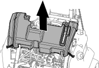
Removing the Hood
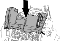
Installing the Hood
Lowering the Operator’s Cushion
Raising the Operator’s Cushion
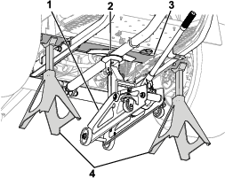
Lifting the Machine
Warning
Mechanical or hydraulic jacks may fail to support the machine and cause serious injury.
Use jack stands when supporting the machine.
-
Raise the mid-mount attachment and optional rear attachment.
-
Park the machine on a level surface; engage the parking brake; shut off the engine; remove the key; and wait for all movement to stop before leaving the machine.
-
If attached, remove the optional rear attachment
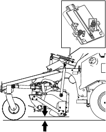
-
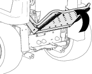
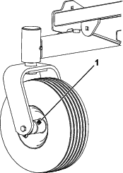
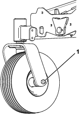
Raise the machine using the designated jacking points as follows:
-
Front—center of the front caster wheel axle as shown in Figure 69.
Warning
The front axle can pivot; ensure that the floor jack is centered on the machine so that it does not shift while lifting; always use 2 jack stands to support the machine once it is lifted.
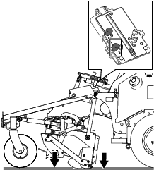
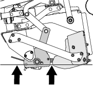
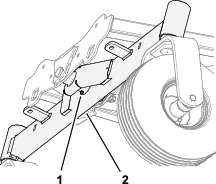
-
Left and right sides—under the rear tube of the frame assembly behind the wheel motors (Figure 70).
-
Lubrication
Greasing the Bearings and Bushings
| Maintenance Service Interval | Maintenance Procedure |
|---|---|
| Every 50 hours |
|
Grease Specification: No. 2 lithium grease
-
Prepare the machine for maintenance; refer to Preparing for Maintenance.
-
Wipe the grease fittings clean
-
Pump grease into the fittings.
-
Wipe off excess grease.
Note: Improper wash-down procedures can negatively affect bearing life. Do not wash down the machine when it is still hot and avoid directing high-pressure or high-volume spray at the bearings or seals.
Engine Maintenance
Engine Safety
-
Shut off the engine before checking the oil or adding oil to the crankcase.
-
Do not change the governor speed or overspeed the engine.
Engine Oil Specification
Use high-quality engine oil that meets the following specifications:
API classification level: SJ or higher
Oil Viscosity: SAE 30—above 4°C (40°F)
Checking the Engine-Oil Level
| Maintenance Service Interval | Maintenance Procedure |
|---|---|
| Before each use or daily |
|
Note: The engine is shipped with oil in the crankcase; however, you must check the oil level before and after you first start the engine.
-
Prepare the machine for maintenance; refer to Preparing for Maintenance.
-
Remove the hood; refer to Removing the Hood.
-
Clean around the dipstick and dipstick tube.
-
Remove the dipstick (Figure 75) and wipe it with a clean rag.
-
Insert the dipstick into the tube (Figure 75) until it is fully seated.
-
Remove the dipstick from the tube and check the oil level.
Important: Ensure that the oil level between the upper and lower mark on the dipstick. If you overfill or underfill the engine oil, you may damage engine when running it.
-
If the oil level is at the LOW mark on the dipstick, add oil as follows:
-
Clean the filler cap and valve cover (Figure 71).
-
Remove the filler cap.
-
Slowly add additional oil to bring the oil level to the F (full) mark on the dipstick.
-
Install the filler cap.
-
-
Fully insert the dipstick into the dipstick tube.
Important: You must fully seat the dipstick in the tube to seal the engine crankcase. Failure to seal the crankcase may result in engine damage.
-
Install the hood; refer to Installing the Hood.
Changing the Engine Oil and Filter
| Maintenance Service Interval | Maintenance Procedure |
|---|---|
| After the first 50 hours |
|
| Every 100 hours |
|
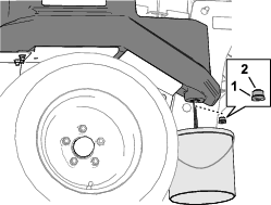
Draining the Engine Oil
Required tools: Drain hose 13 mm (1/2 inch)
-
Start the engine and let it run for 5 minutes.
Note: This warms oil drains better.
-
Prepare the machine for maintenance; refer to Preparing for Maintenance.
-
Remove the hood; refer to Removing the Hood.
-
Remove the cap from the oil-drain valve, assemble a hose 13 mm (1/2 inch) onto the barbed fitting of the valve, and place the other end of the hose into a drain pan (Figure 77).
-
Open the drain valve by rotate it counterclockwise slightly and pulling it outward (Figure 77).
-
When the oil has drained, push in drain valve, rotate it clockwise until it latches, and remove the hose.
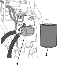
Replacing the Oil Filter
-
Rotate the oil filter counterclockwise to remove it (Figure 78).
-
Wipe the filter adapter with a clean rag.
-
Fill the new oil filter with the specified oil; refer to Engine Oil Specification.
-
Allow 1 to 2 minutes for the oil to be absorbed by filter element, then pour off the excess oil.
-
Apply a thin coat of oil to the gasket of the filter (Figure 78).
-
Thread the oil filter onto the filter adapter until the rubber gasket contacts the filter adapter, then tighten the filter an additional 1/2 turn (Figure 78).
Adding Oil to the Engine
Oil Quantity: with the filter 2.0 L (2.1 US qt)
-
Remove the fill cap from the valve cover (Figure 73) and slowly pour approximately 80% of the specified amount of oil: 2.0 L (2.1 US qt) into the filler neck of the valve cover.
-
Check the oil level.
-
Slowly add additional oil to bring the oil level to the F (full) mark on the dipstick (Figure 67).
-
Install the fill cap.
-
Fully insert the dipstick into the dipstick tube.
Important: You must fully seat the dipstick in the tube to seal the engine crankcase. Failure to seal the crankcase may result in engine damage.
-
Install the hood; refer to Installing the Hood
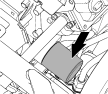
Servicing the Air Cleaner
Removing the Air Filter
| Maintenance Service Interval | Maintenance Procedure |
|---|---|
| Every 250 hours |
|
-
Prepare the machine for maintenance; refer to Preparing for Maintenance.
-
Lower the operator’s pad; refer to Lowering the Operator’s Cushion.
-
Release the latches securing the air-cleaner cover to the air-cleaner body (Figure 65).
-
Remove the cover from the air-cleaner body.
-
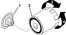
Remove the dirt-ejection port from the cover, clean the cavity of the port and the cover, and assemble the ejection port onto the cover (Figure 65).
-
Before removing the filter element, use low-pressure air (40 psi, clean and dry) to help remove large accumulations of debris packed between the outside of the element and the air-cleaner body.
Important: Avoid using high-pressure air, which could force dirt through the filter into the intake tract. This cleaning process prevents debris from migrating into the intake when the primary filter is removed.
-
Remove the filter element.
Note: Do not cleaning a used element because you may damage the filter media.
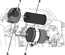
Installing the Air Filter
-
Inspect the new filter for shipping damage, checking the sealing end of the filter and the body.
Important: Do not use a damaged element.
-
Insert the new filter by applying pressure to the outer rim of the element to seat it in the canister.
Note: Do not apply pressure to the flexible center of the filter.
-
Assemble the air-cleaner cover to the air-cleaner body, and secure the cover with the latches.
-
Raise the operator’s pad; refer to Raising the Operator’s Cushion.
Servicing the Spark Plug(s)
| Maintenance Service Interval | Maintenance Procedure |
|---|---|
| Every 200 hours |
|
| Every 500 hours |
|
Removing the Spark Plug
-
Prepare the machine for maintenance; refer to Preparing for Maintenance.
-
Remove the hood; refer to Removing the Hood.
-
Clean the area around the base of the plug(s) to keep dirt and debris out of the engine.
-
Remove the 2 spark-plug wires as shown in Figure 82.
Note: Use a spark-plug socket when removing the spark plugs.
-
Remove the spark plugs.
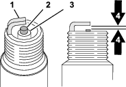
Checking the Spark Plug
-
Check the spark plug—if you see light brown or gray on the insulator, the engine is operating properly.
Note: A black coating on the insulator may mean the air cleaner is dirty.
Important: Do not clean the spark plug(s). Always replace the spark plug(s) when it has a black coating, worn electrodes, an oily film, or cracks.
-
Adjust the air gap (Figure 83) between the center electrode and side electrode to 0.76 mm (0.030 inch).
-
Repeat steps 1 and 2 for the other spark plug.
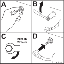
Installing the Spark Plug
-
Install and torque the 2 spark plugs (Figure 78).
Note: Use a spark-plug socket and torque wrench to tighten the spark plugs.
-
Install the spark-plug wires onto the spark plugs.
-
Install the hood; refer to Installing the Hood
Fuel System Maintenance
Danger
Under certain conditions, fuel is extremely flammable and highly explosive. A fire or explosion from fuel can burn you and others and can damage property.
-
Drain fuel from the fuel tanks when the engine is cold. Do this outdoors in an open area. Wipe up any fuel that spills.
-
Never smoke when draining fuel, and stay away from an open flame or where a spark may ignite the fumes.
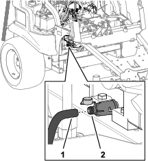
Changing the Fuel Filter
| Maintenance Service Interval | Maintenance Procedure |
|---|---|
| Every 200 hours |
|
-
Park the machine on a level surface, engage the parking brake, and move the throttle to the SLOW position.
-
If installed, lower the mid-mount attachment and optional rear attachment.
-
Shut off the engine and remove the key.
-
Wait for all moving parts to stop and allow machine components to cool.
-
Loosen the fuel tank cap to relieve pressure.
Note: To avoid spilling fuel, you may drain the tank before replacing the filter; refer to Draining the Fuel Tank.
-
Remove the hood; refer to Removing the Hood.
-
Clamp the fuel lines on both sides of the fuel filter (Figure 85).
-
Squeeze the ends of the hose clamps together and slide them away from the filter (Figure 85).
-
Place a drain pan under the fuel lines to catch any leaks, then remove the filter from the fuel lines.
-
Slide the fuel lines on the new fuel filter fittings, ensuring that the arrow on the filter points away from the fuel line coming from the fuel tank and toward the line going to the fuel pump.
Important: Never install a dirty filter.
-
Move the hose clamps close to the filter.
-
Remove the clamp blocking fuel flow and open the fuel valves.
-
Secure the fuel tank cap and install the hood; refer to Installing the Hood.
Draining the Fuel Tank
-
Park the machine on a level surface, engage the parking brake, and move the throttle to the SLOW position.
-
If installed, lower the mid-mount attachment and optional rear attachment.
-
Shut off the engine and remove the key.
-
Wait for all moving parts to stop and allow machine components to cool.
-
Syphon the fuel from the tank using a pump-type syphon.
Electrical System Maintenance
Replacing the Fuses
-
Prepare the machine for maintenance; refer to Preparing for Maintenance.
-
Lower the operator’s cushion; refer to Lowering the Operator’s Cushion.
-
Remove the open fuse from the fuse block (Figure 80).
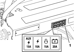
-
Insert a new fuse of the same amperage into the fuse-block slot.
-
Raise and secure the operator’s cushion; refer to Raising the Operator’s Cushion.
Drive System Maintenance
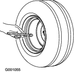
Checking the Tire Air Pressure
| Maintenance Service Interval | Maintenance Procedure |
|---|---|
| Every 50 hours |
|
Incorrect tire air pressure can cause an uneven performance of the mid-mount attachment.
Note: Check the tires when they are cold to get accurate air-pressure readings.
-
Measure the tire pressure before operating the machine.
Note: The specified air pressure for the front and rear tires are 124 kPa (15 psi).
-
If needed, adjust the air pressure in the tires to the specified air pressure.
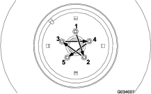
Torquing the Wheel Lug Nuts
| Maintenance Service Interval | Maintenance Procedure |
|---|---|
| Monthly |
|
Wheel-lug nut torque specification: 129 N∙m (95 ft-lb).
Torque the lug nuts at the rear wheels in the pattern as shown in Figure 88 to the specified torque.
Torquing the Caster Wheel Nuts
Note: This is only necessary after removing or replacing the front caster wheels.
Tighten the locknut until the wheel no longer spins freely, then slowly loosen the locknut just enough so the wheel can spin freely; repeat this for the other caster wheel.
Belt Maintenance
Replacing the Belt
| Maintenance Service Interval | Maintenance Procedure |
|---|---|
| Every 1,000 hours |
|
-
Prepare the machine for maintenance; refer to Preparing for Maintenance.
-
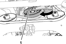
At the bottom, front of the engine, insert a socket wrench or breaker bar into the idler tension arm, and move the bracket up to relieve belt tension (Figure 90).
-
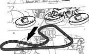
Slip the belt from the pulleys (Figure 91).
-
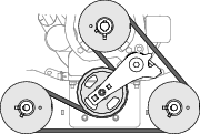
Route the new belt around the pulleys as shown in Figure 92.
-
Remove the socket wrench or breaker bar from the idler tension arm.
Hydraulic System Maintenance
Hydraulic System Safety
-
Seek immediate medical attention if fluid is injected into skin. Injected fluid must be surgically removed within a few hours by a doctor.
-
Ensure that all hydraulic-fluid hoses and lines are in good condition and all hydraulic connections and fittings are tight before applying pressure to the hydraulic system.
-
Keep your body and hands away from pinhole leaks or nozzles that eject high-pressure hydraulic fluid.
-
Use cardboard or paper to find hydraulic leaks.
-
Safely relieve all pressure in the hydraulic system before performing any work on the hydraulic system.
Checking the Hydraulic Lines and Hoses
| Maintenance Service Interval | Maintenance Procedure |
|---|---|
| Before each use or daily |
|
Check the hydraulic lines and hoses daily for leaks, kinked lines, loose mounting supports, wear, loose fittings, weather deterioration, and chemical deterioration. Make all necessary repairs before operating.
Hydraulic-Fluid Specifications
Recommended fluid: Toro Premium Transmission/Hydraulic Tractor Fluid (available in 5-gallon pails or 55-gallon drums. See the Parts Catalog or contact an authorized Toro distributor for part numbers.)
Alternate fluids: If the Toro fluid is not available, Mobil® 424 hydraulic fluid may be used.
Note: Toro does not assume responsibility for damage caused by improper substitutions.
Note: Many hydraulic fluids are almost colorless, making it difficult to spot leaks. A red dye additive for the hydraulic-system fluid is available in 20 ml (2/3 fl oz) bottles. 1 bottle is sufficient for 15 to 22 L (4 to 6 gallons) of hydraulic fluid. Order Part Number 44-2500 from your authorized Toro distributor.
Checking the Hydraulic-Fluid Level
| Maintenance Service Interval | Maintenance Procedure |
|---|---|
| Before each use or daily |
|
-
Fully raise all hydraulic attachment to the transport position.
-
Prepare the machine for maintenance; refer to Preparing for Maintenance.
-
Remove the hood; refer to Removing the Hood.
-
Clean the area around the hydraulic-tank dipstick and cap (Figure 93).
-
Remove the dipstick and cap from the tank and wipe it with a clean rag.
-
Insert the dipstick into the tank (Figure 93).
-
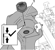
Remove dipstick and cap (Figure 93) and check the level of the fluid.
Note: You should see the fluid level is between the LOW mark and the FULL mark on the dipstick.
-
If the fluid level is low, add the specified hydraulic fluid to the reservoir to raise the level to the FULL mark on the dipstick.
-
Install the dipstick and cap (Figure 93) into the tank.
-
Install the hood; refer to Installing the Hood.
Changing the Hydraulic Filter
| Maintenance Service Interval | Maintenance Procedure |
|---|---|
| Every 300 hours |
|
Removing the Hydraulic Filter
-
Prepare the machine for maintenance; refer to Preparing for Maintenance.
-
Lower the operator’s cushion; refer to Lowering the Operator’s Cushion.
-
Align the drain pan under the hydraulic filter.
-
Remove the filter from the filter head (Figure 94).
Installing the Filter
-
Clean the filter mounting flange of the filter head.
-
Apply a thin coat of the specified hydraulic fluid to the gasket of the new filter; refer to Hydraulic-Fluid Specifications.
-
Fill the filter with the specified hydraulic fluid.
-
Thread the filter onto the filter head until the seal contacts the mounting flange, then tighten the filter an additional 1/2 turn.
-
Star the engine, check for leaks around the filter and filter head, shut off the engine, and remove the key.
Note: Repair all hydraulic leaks.
-
Raise and secure the operator’s cushion; refer to Raising the Operator’s Cushion.
Changing the Hydraulic Fluid
| Maintenance Service Interval | Maintenance Procedure |
|---|---|
| Every 300 hours |
|
Draining the Tank
Hydraulic-tank capacity: 28.4 L (7.5 US gallons)
-
Prepare the machine for maintenance; refer to Preparing for Maintenance.
-
Remove the hood; refer to Removing the Hood.
-
Align a drain container with a 30 L (8 US gallons) or larger capacity under the forward corner of the hydraulic tank (Figure 95).
-
Remove the drain plug from the tank, and wait for the hydraulic fluid to drain.
-
Check the drain plug for steel fragments.
Note: Contact your authorized Toro distributor if the end of the plug is covered with steel fragments.
-
Check the O-ring of the drain plug for damage or wear.
Important: Replace a damaged or worn O-ring.
Filling the Tank
-
Wipe clean the drain plug and install it into the tank.
-
Add 28.4 L (7.5 US gallons) of the specified hydraulic fluid into the hydraulic tank.
-
Check the drain plug for leaks.
Important: Repair all hydraulic leaks.
-
Install the hood; refer to Installing the Hood.
Cleaning
Cleaning the Machine
| Maintenance Service Interval | Maintenance Procedure |
|---|---|
| After each use |
|
Important: Do not use brackish or reclaimed water to clean the machine.
Important: Do not pressure wash the machine
-
Park the machine on a level surface, fully raise and latch the handlebar to engage the parking brake, shut off the engine, remove the key, and wait for all moving parts to stop.
-
Thoroughly wash the machine.
-
Use a garden hose without a nozzle to avoid forcing water past the seals and contaminating bearing grease.
-
Use a brush to remove caked-on material.
-
Use mild detergent to clean the covers.
-
-
After cleaning, apply a coat of auto wax periodically to maintain the glossy finish of the cover.
-
Inspect the machine for damage, oil leaks, and component wear.