Whenever you need service, genuine Toro parts, or additional information, contact an Authorized Service Dealer or Toro Customer Service and have the model and serial numbers of your product ready. Figure 1 illustrates the location of the model and serial numbers on the product.

g028646

Note: Determine the left and right sides of the machine from the normal operating position.

The EU Compliance Kit is designed to meet German safety requirements by enabling operators to clean out residual chemicals from the sprayer system and clean the external machine while bypassing the chemical tank. It is a dedicated kit for a turf spray application vehicle and is intended to be used by professional, hired operators in commercial applications.

This product complies with all relevant European directives. For details, please see the Declaration of Incorporation (DOI) at the back of this publication.

Read this manual carefully to learn how to operate and maintain your product properly. The information in this manual can help you and others avoid injury and product damage. Although Toro designs and produces safe products, you are responsible for operating the product properly and safely.

Safety

This manual identifies potential hazards and has safety messages identified by the safety alert symbol (Figure 2), which signals a hazard that may cause serious injury or death if you do not follow the recommended precautions.

g000502

This manual uses 2 other words to highlight information. Important calls attention to special mechanical information and Note emphasizes general information worthy of special attention.

Also read the safety and operation instructions in the vehicle Operator’s Manual.

Chemical Safety

Warning

Chemical substances used in the spray system may be hazardous and toxic to you, bystanders, animals, plants, soils or other property.

  • Carefully read and follow the chemical warning labels and Material Safety Data Sheets (MSDS) for all chemicals used and protect yourself according to the chemical manufacturer's recommendations. For example, use appropriate Personal Protective Equipment (PPE) including face and eye protection, gloves, or other equipment to guard against personal contact with the chemical.

  • Keep in mind that there may be more than one chemical used and information on each should be assessed.

  • Refuse to operate or work on the sprayer if this information is not available!

  • Before working on a spray system, make sure the system has been triple rinsed and neutralized according to the recommendations of the chemical manufacturer(s).

  • Verify there is an adequate supply of clean water and soap nearby, and immediately wash off any chemicals that contact you.

  • Obtain proper training before using or handling chemicals.

  • Use the correct chemical for the job.

  • Follow the chemical manufacturer's instructions for the safe application of the chemical.

  • Handle chemicals in a well ventilated area.

  • Wear goggles and other protective equipment as instructed by the chemical manufacturer. Ensure that as little skin as possible is exposed while using chemicals.

  • Have clean water available especially when filling the spray tank.

  • Do not eat, drink, or smoke while working with chemicals.

  • Always wash your hands and other exposed areas as soon as possible after finishing the work.

  • Properly dispose of unused chemicals and chemical containers as instructed by the chemical manufacturer and your local codes.

  • Chemicals and fumes in the tanks are dangerous; never enter the tank or place your head over or in the opening.

  • Follow all local, state, and federal requirements for the spraying of chemicals.

Hand Sprayer Safety

  • Do not aim the hand sprayer at any person or animal. Fluids under high pressure can penetrate skin and cause severe injury, possibly resulting in amputation or death. Hot liquids and chemicals can also cause burns or injury. If any part of the body comes in contact with the spray stream, immediately consult a physician familiar with injected fluid injuries.

  • Do not place your hand or any other part of your body in front of the spray nozzle.

  • Do not leave the equipment under pressure when you are not present.

  • Do not use the hand sprayer if the hose, trigger lock, nozzle, or any other part is damaged or missing.

  • Do not use the hand sprayer if there are any leaks in any hoses, fittings, or other components.

  • Do not spray near power lines; the spray stream could contact the power lines and give you a potentially fatal electrical shock.

  • Do not drive while spraying with a hand sprayer.

  • Wear rubber gloves, safety goggles, and a full-body protective suit when spraying chemicals with the hand sprayer.

  • Lightning can cause severe injury or death. If lightning is seen or thunder is heard in the area, do not operate the machine; seek shelter.

Safety and Instructional Decals

Graphic

Safety decals and instructions are easily visible to the operator and are located near any area of potential danger. Replace any decal that is damaged or lost.

decal120-0673
decal120-0687

Setup

Preparing the Machine

  1. Move the sprayer onto a level surface, set the parking brake, stop the pump, stop the engine, and remove the ignition key.

  2. Drain the contents of the tank to remove any chemicals in the lines. Refer to the Operator’s Manual for more information.

    Note: Take caution while disconnecting any hoses during the installation of this kit, and have a catch bucket ready for any chemicals remaining in the hose.

Caution

Chemicals are hazardous and can cause personal injury.

  • Read the directions on the chemical labels before handling the chemicals, and follow all manufacturer recommendations and precautions.

  • Keep chemicals away from your skin. Should contact occur, wash the affected area thoroughly with soap and clean water.

  • Wear goggles and any other protective equipment recommended by the chemical manufacturer.

Installing the Rinse Tank

Parts needed for this procedure:

Carriage bolt (5/16 x 1 inch)2
Spray-gun bracket1
Clamp2
Flanged locknut (5/16 inch)2
Carriage bolt (3/8 x 1 inch)1
Carriage bolt (3/8 x 1-1/4 inch)2
Flange locknut3
Rinse tank1
Filler cap1
Bulkhead fitting1
Plastic flange nut1
Retainer1
90-degree barbed fitting1
Right rinse-tank bracket1
Hose mount1
Left rinse-tank bracket1
Spacer (3/8 x 1/4 inch)1

Removing the Fresh Water Tank

  1. If filled with water, empty the fresh water tank.

  2. Remove the 4 flanged head bolts that secure the fresh water tank to the mounting bracket (Figure 3).

    g029035
  3. Remove the tank from the machine (Figure 3).

    Note: Retain the fresh water tank and flanged head bolts for installation in Installing the Fresh Water Tank.

Installing the Hardware for the Rinse Tank Straps and Spray Gun Bracket

  1. Assemble the 2 clamps to the spray-gun bracket (Figure 4) with 2 carriage bolt (5/16 x 1 inch) and 2 flanged locknuts (5/16 inch).

    g028623
  2. Remove and retain the bolt (3/8 x 5 inch), washers, and flanged locknut that secure the front tank straps at the top of the tank (Figure 5).

    Note: Retain the bolt (3/8 x 5 inch), washers, and flanged locknut; discard the short carriage bolt and locknut holding the R-clamp in place.

    g028626
  3. Install a carriage bolt (3/8 x 1 inch) in the upper-inboard holes of the left, front tank strap (Figure 6).

    Note: Loosely thread a flanged locknuts (3/8 inch) onto the carriage bolt.

    g028625
  4. Install 1 carriage bolt (3/8 x 1-1/4 inch) in the upper-inboard holes of the right, front tank strap (Figure 6).

    Note: Loosely thread a flanged locknuts (3/8 inch) onto the carriage bolt.

  5. Install 1 carriage bolts (3/8 x 1-1/4 inch) in the lower-outboard holes of the right, front tank strap (Figure 6).

    Note: Loosely thread a flanged locknuts (3/8 inch) onto the carriage bolts.

  6. Install the tank strap hardware that you removed in 2 to secure the straps to the tank.

    Note: Ensure that the square portion of the carriage bolts are seated in the square opening in the tank straps.

    Note: Make sure that the straps are flush to the tank. Do not overtighten tank strap hardware.

  7. Remove the flanged locknut (3/8 inch) at the lower-outboard carriage bolt at the right, front tank strap, assemble the spray gun bracket to the carriage bolt, and secure the bracket with the flanged locknut (Figure 7).

    g028624

Installing the Tank

  1. Install the bulkhead fitting into the rinse tank as follows:

    1. Install the flanged seal onto the bulkhead fitting (Figure 8).

      g028628
    2. Attach a wire, longer than the tank is tall, to one of the retaining-fork holes in the bulkhead fitting (Figure 8 and Figure 9)

      g014228
    3. Remove the tank cap, insert the wire through the filler neck, and pass the wire out through the outlet at the bottom of the tank (Figure 9).

    4. Use the wire to guide the bulkhead fitting to the outlet (Figure 10).

      g014229
    5. Move the bulkhead fitting into position making sure that the flanged gasket seats against the interior wall of the rinse tank (Figure 10)

    6. Secure the bulkhead fitting to the rinse tank with a plastic flange nut

      Note: Remove the wire from the bulkhead fitting.

      g014230
    7. Install a 90° barbed fitting onto the bulkhead fitting and secure the barbed fitting with a retainer (Figure 12).

      Note: Rotate the 90° barbed fitting so that it faces rearward.

      g014260
  2. Release the 2 latches that secure the guard behind the seat to the chassis and remove the guard from the machine (Figure 13).

    g028641
  3. Remove the 2 flanged locknuts at the carriage bolts at the upper-inboard hole of the left-and right, front tank straps.

  4. Align the rinse tank to the sprayer tank as shown in Figure 14.

    g028643
  5. Align the left tank bracket onto the carriage bolt (3/8 x 1 inch) at the upper-inboard holes of the left, front strap (Figure 14).

    Note: Ensure that the tank bracket is aligned with the pocket molded into the top rear part of the rinse tank.

    Note: Replace the R-clamp during this time too.

  6. Secure the tank bracket to the carriage bolt and strap (Figure 14) with a flanged locknut (3/8 inch).

  7. Align the hose mount, spacer (3/8 x 1/4 inch), and right tank bracket onto the carriage bolt (3/8 x 1 inch)at the upper-inboard hole of the right-front strap. (Figure 15).

    Note: Ensure that the tank bracket is aligned with the pocket molded into the top rear part of the rinse tank.

    g028642
  8. Secure the hose mount, spacer, and tank bracket to the carriage bolt and strap (Figure 15) with a flanged locknut (3/8 inch).

Note: Once the rinse tank has been initially filled with water, check the rinse-tank bracket fasteners and tightened the nuts as needed because the weight of the liquid in the tank can further seat the tank against the frame.

Installing the Fresh Water Tank

  1. Align the holes in the fresh water tank with the slots in the mounting bracket; refer to Figure 3 in Removing the Fresh Water Tank.

  2. Assemble the tank to the bracket with the 4 flanged-head bolts that you removed in step 2 of Removing the Fresh Water Tank.

  3. Torque the bolts to 1017 to 1355 N-cm (90 to 120 in-lb).

Installing the Rinse Nozzles

Parts needed for this procedure:

90° barbed fitting (3/4 inch NPT x 3/4 inch)2
Plastic flange nut2
Bulkhead fitting2
Rinse nozzle2
Bushing2
Rinse vane2
Shoulder bolt2

Drilling the Main Tank

  1. Open the tank lid and remove the strainer basket.

  2. Locate the 2 drill marks on the main tank (Figure 16).

    g022212
  3. Use a 4 cm (1-5/8 inch) hole saw to drill a hole at each drill mark.

    Note: Place a receptacle inside the tank and below the areas to be drilled to catch any debris created during the cutting.

    Important: Debris left inside a tank could clog and damage the spray system during operation.

    Note: Drilling counter clockwise will make drilling easier.

Installing the Nozzles

Note: Apply PTFE tape to the threads of the taper-threaded fittings used in the sprayer and rinse systems.

  1. Assemble the 2 rinse nozzles as shown in Figure 17.

    g022281
  2. Open the cover of the sprayer tank.

  3. Assemble the nozzle assemblies up through the drilled holes (Figure 18).

    g022282
  4. At top of the tank, install the plastic flange nuts over the exposed threads of the bulkhead fittings for the rinse nozzles(Figure 18).

    Note: Ensure that the seal is seated flush between the bulkhead fitting and the underside of the tank.

  5. Install a 90° barbed fitting (3/4 inch NPT x 3/4 inch) onto each of the threaded openings of the rinse-nozzle bulkheads (Figure 19).

    g022283
  6. Align the 90° barbed fittings toward the middle of the right side of the machine.

Installing the Rinse Pump

Parts needed for this procedure:

Carriage bolt (3/8 x 1 inch)2
Flanged Locknuts (3/8 inch)2
Rinse-pump mounting bracket1
Straight-barbed fitting (1/2 inch NPT x 1/2 inch)2
Nipple (1/2 inch NPT)1
Pressure filter1
Rinse pump1
Valve mount1
Bolt (1/4 x 1-3/4 inch)4
Washer (1/4 inch)4
Serrated-flange nut4
Small hairpin2

Installing the Valve Mount

  1. Remove the bolt (3/8 x 5 inch), washers, flanged locknut, and hairpin that secure the right, rear tank straps at the top of the tank.

    Note: Retain the bolt (3/8 x 5 inch), washers, flanged locknut, and hairpin.

  2. Install 1 carriage bolt (3/8 x 1 inch) in the upper-inboard holes of the right, rear tank strap (Figure 20).

    Note: Loosely thread a flanged locknuts (3/8 inch) onto the carriage bolt.

    g024697
  3. Install 1 carriage bolts (3/8 x 1 inch) in the lower-outboard holes of the right, rear tank strap (Figure 20).

  4. Install the tank strap hardware that you removed in 1 to secure the straps to the tank.

    Note: Ensure that the square portion of the carriage bolts are seated in the square opening in the tank straps.

    Note: Make sure that the straps are flush to the tank. Do not overtighten tank strap hardware.

  5. Assemble the valve mount to the 2 carriage bolts (3/8 x 1 inch) using 2 flange locknuts (Figure 20).

Assembling the Pressure Filter and Rinse Pump

Note: Apply PTFE tape to the threads of the taper-threaded fittings used in the sprayer and rinse systems.

  1. Assemble nipple (1/2 inch NPT x 1/2 inch) into the inlet of the pressure filter assembly and the straight-barbed fitting (1/2 inch NPT x 1/2 inch) into the outlet (Figure 21).

    Note: The arrow at the top of the pressure filter points to the outlet side of the filter head.

    g024704
  2. Assemble the pressure-filter assembly onto the rinse pump at the nipple (Figure 22).

    Note: When the nipple is tight, ensure that the filter and pump are aligned vertically.

    g025034
  3. Secure the rinse pump and rinse pump mounting bracket to the valve mount (Figure 23) with the 4 bolts (1/4 x 1-3/4 inch), 4 washers (1/4 inch), and 4 serrated-flange nuts (1/4 inch).

    g025042
  4. Install a straight-barbed fitting (1/2 inch NPT x 1/2 inch) into the inlet port of the rinse pump.

  5. Secure the rinse-pump cover to the rinse-pump mounting bracket with the 2 hair pins.

Assembling and Mounting the 4-Way Valve

Parts needed for this procedure:

4-way valve1
Straight-barbed fitting(1 inch NPT x 3/4 inch)1
90-degree barbed fitting (1 inch NPT x 3/4 inch)2
Straight-barbed fitting (3/4 inch NPT x 1/2 inch)1
Reducer fitting (1 inch NPT x 3/4 inch NPT)1
Faceplate bracket1
Valve-mount assembly1
Bolt (6 mm)4
Flat washer (6 mm)4
Locknut (6 mm)4
Nut (3/8 inch)2
Bolt (3/8 inch)2

Note: Apply PTFE tape to the threads of the taper-threaded fittings used in the sprayer and rinse systems.

  1. Assemble the 90°-barbed fittings, straight-barbed fitting (1 inch NPT x 3/4 inch), reducer fitting, and straight-barbed fitting (3/4 inch NPT x 1/2 inch) into the 4-way valve as shown in Figure 24.

    Important: Align the 90° barbed fittings as shown in Figure 24.

    g024698
  2. Insert 4 bolts (6 x 16 mm) and 4 washers (6 mm) into the slots of the 4-way valve (Figure 25).

    g015856
  3. Assemble the 4-way valve onto the valve mount (Figure 26) with 4 locknuts (6 mm).

    g024703
  4. Install the faceplate bracket onto the valve-mount assembly (Figure 27) with 2 flange bolts (5/16 x 1 inch) and 2 flange locknuts (5/16 inch).

    g024700

Installing the Rinse-Pump Switch, Pump Connectors, and Fuse

Parts needed for this procedure:

Fuse, 40-amp1
Dash switch1

Installing the Rinse-Pump Switch

  1. Tilt the operator’s seat forward and secure it with the prop rod (Figure 28).

    g028652
  2. Remove the flanged locknut, carriage bolt, and positive battery cable from the battery (Figure 28).

  3. Locate the plug where you will install the rinse-tank switch at the left side of the console (Figure 29).

    Note: It is the first plug to the right of the lockout key.

    g022218
  4. Remove the plug from the side of the console (Figure 29).

  5. From below the console, locate the 8-socket electrical connector labeled “Rinse Tank” in the main harness.

  6. Remove the plastic tie that secures the rinse tank connector to the wiring bundle and route the connector to the opening that you made in the console.

  7. Through the opening in the console, connect the 8-pin connector of the 3-position rocker switch into the 8-socket rinse tank connector (Figure 29).

  8. Push the switch into the opening in the console until the switch snaps into position.

Connecting the Rinse Pump Connector

  1. Align the 2-socket electrical connector of the wiring harness for the machine with the 2-pin electrical connector for the rinse pump (Figure 30).

    g028990
  2. Press the 2 connectors together until the latch in the 2-socket connector snaps securely (Figure 30).

Installing the Fuse

  1. At the fuse block, remove the 30 amp fuse (Figure 31).

    g028653
  2. At the same socket that you removed the 30 amp fuse, insert a 40 amp fuse (Figure 31).

  3. Connect the positive battery cable to the battery (Figure 28).

  4. Lower the operator’s seat (Figure 28).

Installing the Ball Valve and Mounting Assembly

Parts needed for this procedure:

Ball valve1
Straight-barbed fitting (1-1/4 inch NPT x 3/4 inch)2
Valve-mount bracket1
Hex-head bolt (5/16 x 5/8 inch)2
Hex-head bolt (6 x 16 mm)2
Locknut (6 mm)2

Note: Apply PTFE tape to the threads of the taper-threaded fittings used in the sprayer and rinse systems.

  1. At the boom-mounting plate for the right frame channel of the machine, measure rearward 15.2 cm (6 inches) and mark a line across the right boom mount that supports the center-boom section (Figure 32).

    g028695g028696
  2. Center the holes of the ball valve bracket to the line that you marked in step 1. and center the bracket to the across right boom mount (Figure 32).

    Note: Use the ball valve bracket for a drilling template.

  3. Mark the holes in the bracket onto the right boom mount and center punch the marks.

  4. Using a drill and a 6.5 mm (1/4 inch) drill bit, drill 2 holes into the frame (Figure 32).

  5. Assemble the ball valve to the ball valve bracket (Figure 33) with 2 bolts (5/16 x 5/8 inch).

    g024826
  6. Install the ball valve and valve mount bracket to the machine with 2 hex-head bolts (6 x 16 mm) and 2 flange nuts (6 mm) (Figure 34).

    g024828

Installing the Upper Tee Assembly

Parts needed for this procedure:

Inlet hose 2.5 x 66 cm (1 x 26 inch)1
Hose clamp2
90° hub fitting2
Large O-ring4
T-Fitting (upper)1
Retainer3
Reducer hub1
Small O-ring1
Transfer hose 1.9 x 61 cm (3/4 x 24 inch)1
Hub connector1

Removing the Inlet Hose

  1. Remove the flange clamp, gasket, flanged elbow, and inlet hose from the pressure filter head (A of Figure 35).

    Note: Retain the gasket and flange clamp for installation later.

    g028611
  2. Remove the retainer that secures the straight-hub fitting of the inlet hose to the lower T-fitting of the sprayer system and remove the inlet hose from the machine (B of Figure 35)

    Note: Retain the retainer for installation in Installing the Upper T-fitting and Inlet Hose.

  3. Remove the flanged elbow and hose clamp from the inlet hose (Figure 35).

    Note: Retain the flanged elbow and hose clamp; discard the old inlet hose and straight-barbed fitting.

Assembling the Upper T-fitting, Inlet Hose and Ball Valve Hose

Note: To insert the barbed fitting into the hose more easily, apply a light coat of a non-petroleum-based lubricant, such as vegetable oil to the barbed end of the fitting.

  1. Insert the flanged elbow that you removed in step 3 of Removing the Inlet Hose into the inlet hose 2.5 x 66 cm (1 x 26 inch) and secure the fitting with the clamp that you retained (Figure 36)

    g029027
  2. Insert the barbed end of a 90° hub fitting into the other end of the inlet hose and secure it with a hose clamp as shown in Figure 36.

    Note: Align the face of the elbow with the face of the 90° hub fitting.

  3. Assemble an O-ring into the O-ring groove of the 90° hub fitting (Figure 36)

  4. Insert the hub of the 90° fitting into one end of the upper T-fitting (Figure 36) and secure the hub fitting the T-fitting with a retainer.

  5. Install the large O-ring into the O-ring groove of the reducer hub and the small O-ring into the O-ring groove of the 90° hub fitting (Figure 37).

    g029028
  6. Install the 90° hub fitting into the reducer hub and secure the fittings with a retainer (Figure 37).

  7. Assemble transfer hose 1.9 x 61 cm (3/4 x 24 inch) onto the barbed end of a 90° hub fitting into and secure the hose and fitting with a hose clamp (Figure 37).

Installing the Upper T-fitting and Inlet Hose

  1. Install the 2 large O-rings into the O-ring grooves at either end of the hub connector (Figure 38)

    g029031
  2. Route the inlet and upper T-fitting that you assembled in Assembling the Upper T-fitting, Inlet Hose and Ball Valve Hose as shown in Figure 39.

    g029032
  3. Install the upper T-fitting onto the hub connector and secure the fitting and connector with the retainer (Figure 39) that you removed in step 2 of Removing the Inlet Hose.

  4. Align the flanged elbow and a the gasket that you removed Secure the flanged elbow the hose with the hose clamp (Figure 40) that you removed in 3 of Removing the Inlet Hose.

    g028699
  5. Secure the inlet hose to the pressure filter head with the gasket and flanged clamp (Figure 40) that you removed in 1 of Removing the Inlet Hose.

Installing the Hose between the Upper T-fitting and the Ball Valve

Parts needed for this procedure:

Hose clamp1
Retainer1

Note: To insert the barbed fitting into the hose more easily, apply a light coat of a non-petroleum-based lubricant, such as vegetable oil to the barbed end of the fitting.

  1. Install the reducer hub at the end of the transfer hose into the inboard port of the upper T-fitting (Figure 41).

    g029033
  2. Secure the reducer hub to the T-fitting with a retainer (Figure 41).

  3. Assemble the free end of the transfer hose over the straight-barbed fitting at the inboard side of the ball valve (Figure 42).

    g029034
  4. Secure the hose to the barbed fitting with a hose clamp (Figure 42).

Installing the Hose between the Ball Valve and the 4-Way Valve

Parts needed for this procedure:

Hose 1.9 x 76 cm (3/4 x 30 inch)1
Hose clamp2

Note: To insert the barbed fitting into the hose more easily, apply a light coat of a non-petroleum-based lubricant, such as vegetable oil to the barbed end of the fitting.

  1. Assemble the end of the Hose 1.9 x 76 cm (3/4 x 30 inch) over the straight-barbed fitting at the outboard side of the ball valve (Figure 43).

    g029025
  2. Secure the hose to the barbed fitting with a hose clamp (Figure 43).

  3. Assemble the free end of the hose 1.9 x 76 cm (3/4 x 30 inch) over the straight-barbed fitting at the back of the 4–way valve (Figure 43).

  4. Secure the hose to the fitting with a hose clamp (Figure 43).

Installing the Hose Between the Pressure-Filter Assembly and the 4-Way Valve

Parts needed for this procedure:

Hose 1.9 x 61 cm (3/4 x 24 inch)1
Hose clamp2

Note: To insert the barbed fitting into the hose more easily, apply a light coat of a non-petroleum-based lubricant, such as vegetable oil to the barbed end of the fitting.

  1. Assemble the hose 1.9 x 61 cm (3/4 x 24 inch) over the 90° barbed fitting at the inboard side of the 4-way valve (Figure 44).

  2. Secure the hose to the fitting with a hose clamp (Figure 44).

    g029024
  3. Assemble the free end of the hose over the straight-barbed fitting and secure the hose to the fitting with a hose clamp (Figure 44).

Installing the Rinse Nozzle Hoses

Parts needed for this procedure:

Hose 1.9 x 48.3 cm (3/4 x 19 inch)2
Hose 1.9 x 61 cm (3/4 x 24 inch)1
Tee fitting1
Hose clamp6

Note: To insert the barbed fitting into the hose more easily, apply a light coat of a non-petroleum-based lubricant, such as vegetable oil to the barbed end of the fitting.

  1. Assemble a hose 1.9 x 48.3 cm (3/4 x 19 inch) onto each of the 90° barbed fittings at the 2 rinse nozzles (Figure 45).

    g028989
  2. Secure the hoses to the 90° barbed fittings with hose clamps (Figure 45).

  3. Insert the barbed T-fitting into free end of each hose (Figure 45).

  4. Align the barbed T-fitting so that the side of the lower barb is flush to the sprayer tank and secure the hoses to the T-fitting with 2 hose clamps (Figure 45).

  5. Assemble a hose 1.9 x 61 cm (3/4 x 24 inch) over the straight-barbed fitting at the forward side of the 4-way valve (Figure 46).

    g029026
  6. Secure the hose to the fitting at the valve with a hose clamp (Figure 46).

  7. Assemble the free end of the hose onto the barbed T-fitting and secure the hose to the fitting with a hose clamp (Figure 46).

Connecting the Spray Hose and Gun

Parts needed for this procedure:

Hose 1.3 x 762 cm (1/2 x 300 inch)1
Spray gun1
Hose clamp2
Spray gun barbed fitting1

Note: To insert the barbed fitting into the hose more easily, apply a light coat of a non-petroleum-based lubricant, such as vegetable oil to the barbed end of the fitting.

  1. Assemble the Spray gun barbed fitting onto the fitting in the spray gun (Figure 47).

  2. Assemble the hose 1.3 x 762 cm (1/2 x 300 inch) onto the pray gun barbed fitting and secure the hose to the fitting with a hose clamp (Figure 47).

    g029045
  3. Place the spray gun in the spray gun bracket, route the hose around the hose mount, and route the free end of the hose to the 4-way valve as shown in Figure 48.

    g028988
  4. Assemble the free end of the hose onto the straight-barbed fitting at the front side of the 4-way valve (Figure 48).

  5. Secure the hose to the fitting with a hose clamp (Figure 48).

Installing the Rinse Tank Hose

Parts needed for this procedure:

Hose (45 inches)1
Hose clamp2
Conduit1

Note: To insert the barbed fitting into the hose more easily, apply a light coat of a non-petroleum-based lubricant, such as vegetable oil to the barbed end of the fitting.

  1. Assemble the hose 1.9 x 114 cm (3/4 x 45.0 inch) onto the straight-barbed fitting at the forward side of the tank rinse pump (Figure 49).

  2. Secure the hose to the fitting with a hose clamp (Figure 49).

    g028986
  3. Slip the hose conduit over the hose leaving about 30 cm (1 ft) of the free end of the hose exposed (Figure 49 and Figure 50).

    g028987
  4. Assemble the free end of the hose onto the 90° barbed fitting at the bottom of the rinse tank (Figure 50).

  5. Secure the hose to the fitting with a hose clamp and finish wrapping the end of the hose with the hose conduit (Figure 50).

Installing Decals

Parts needed for this procedure:

Decal (120-0673)1
Decal (120–0687)1
  1. Thoroughly clean the surface of the 4-way valve bracket and ball valve bracket (Figure 51 and Figure 52).

    g029029
    g029046
  2. Peel the backing from the decal and install the decals to the machine as shown in Figure 51 and Figure 52).

Operation

Tank Clean Rinse Kit Operation

Using the Tank Clean Rinse Kit creates a rinsate; a diluted solution of residual chemicals. In many cases it is appropriate to apply the rinsate onto the treated areas. However, before doing so, check with the manufacturer of the chemical to ensure that the application of a diluted solution to the treated areas will not adversely affect the performance of the product.

Important: The Tank Clean Rinse Kit is not intended to dislodge clumped masses of wetable powder or “water-soluble” chemicals that occur when chemicals are not properly introduced into the main tank.

Configuring the Valves for the Rinse System

Note: Do not set the valves in any other configuration except those shown below.

  • This is the tank rinsing configuration (Figure 53). Use this configuration to spray rinse water out of the rinse nozzles in the tank.

    Note: The ball valve must be in this position when using the spray system.

    g015767
  • This is the spray gun configuration (Figure 54). Use this configuration to spray rinse water out of the hand spray gun.

    Note: The ball valve must be in this position when using the spray system.

    g015768
  • This is the boom configuration (Figure 55). Use this configuration to spray rinse water out of the booms.

    Important: Do not set the ball valve in this position when you operate the main chemical pump.

    g015769

Controls

The Tank Clean Rinse Kit is controlled by a 3-position switch.

  • Up: the rinse pump is on, the switch will lock in the up position, and the delay timer is activated.

  • Neutral: the rinse pump is off and switch is in a middle position.

  • Down: the rinse pump is on, the switch must be held in the down position, and the delay timer in not activated.

g025038

Pressing the switch up engages a timed rinse. The pump engages for 60 seconds and pumps approximately 1/3 of the rinse tank contents into the main tank. During this time, the switch will stay in the up position. After 60 seconds, the pump stops running. The switch will remain in the up position until moved to the center or neutral position.

When the switch is in the Neutral position the power is not supplied to the pump and the rinse kit is off.

Pressing the switch Down engages a momentary switch. Power is supplied to the pump for the duration in which the switch is held down. Release pressure and the switch will move to the Neutral position and power will not be supplied to the pump. While the switch is held in the down position the pump will run.

Filling the Tank

Replace the cap

  1. Shut off the sprayer pump, move the sprayer to a level surface and set the parking brake.

  2. Shut off the engine and remove the key from the key switch.

  3. Remove the cap from the rinse tank and fill the tank with approximately 66 L (17.5 US gallons) of clean water.

  4. Install the cap onto the filler neck of the rinse tank.

Important: The 66 L (17.5 US gallons) rinse tank is only intended to be filled with clean water. The introduction of any other substance to the rinse tank can cause a safety hazard and/or damage the machine.

Using the Rinse Cycle

Using the rinse cycle allows the vehicle to be moving during the rinse processes.

  1. Position the sprayer on a level surface, set the parking brake, stop the pump, stop the engine, and remove the ignition key.

  2. Remove the rinse tank cap and fill the tank with approximately 66 L (17.5 US gallons) of clean water. Replace the cap

    Important: The 66 L (17.5 US gallon) rinse tank is only intended to be filled with clean water. The introduction of any other substance to the rinse tank can cause a safety hazard and/or will damage the machine.

  3. Turn the rinse pump on by setting the rinse-pump switch as follows:

    • Press the switch to the up position for a timed rinse.

    • Press and hold down the switch to manually run the pump for the desired duration.

  4. Once the rinse pump has transferred 22 L (5.8 US gallons) of water in the sprayer tank, the user can use the agitation switch of the sprayer system to circulate the clean water through the agitation loop.

  5. Empty the rinsate out if the sprayer tank using 1 of the following procedures:

    Important: Dispose of the rinseate as required by Federal, State and Local regulations

    • Spray the rinsate through the booms until the main tank is empty.

    • Drain the main tank contents into a suitable container and dispose of the diluted solution as required by federal, state or local regulations.

  6. Repeat steps 2 through 5 for 2 additional cycles.

Maintenance

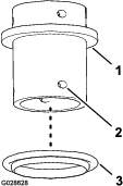
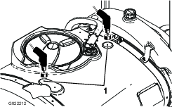
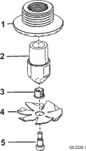
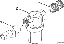
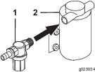
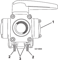
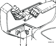
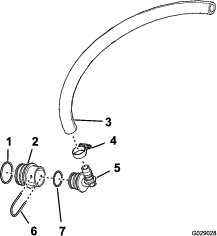
Inspecting the Rinse Pump Filter
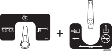
Maintenance Service IntervalMaintenance Procedure
After the first 5 hours
  • Inspect the rinse pump filter
  • Every 50 hours
  • Inspect the rinse pump filter
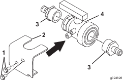
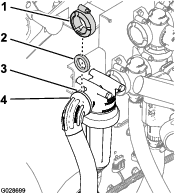
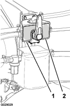
  • Check the filter for any signs of damage. Replace if any damage is found.

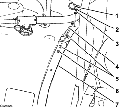
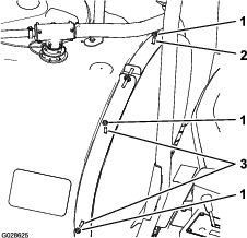
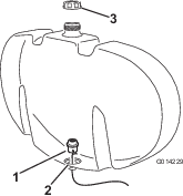
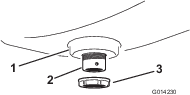
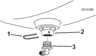
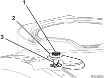
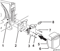
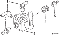
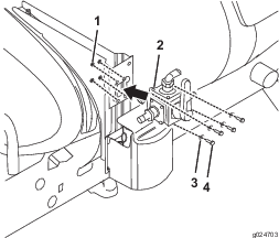
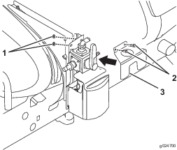
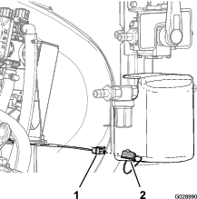
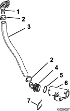
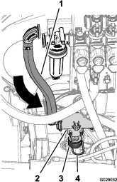
    Inspecting the Rinse System for Leaks and Damage
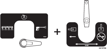
    Maintenance Service IntervalMaintenance Procedure
    After the first 5 hours
  • Inspect the hoses for damage.
  • Before each use or daily
  • Inspect the hoses for leaks.
  • Every 100 hours
  • Inspect the hoses and O-rings for damage.
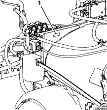
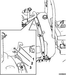
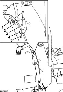
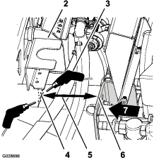
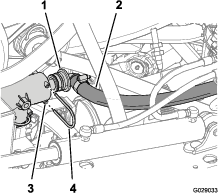
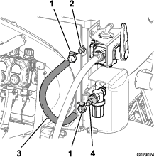
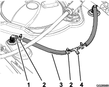
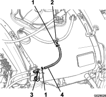
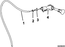
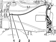
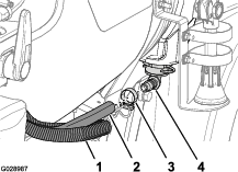
  • After the first 5 hours of operation, inspect all hoses and connections for any leaks or signs of damage. Inspect the hose clamps and retaining forks. Verify that all connections are secure. Replace any damaged parts. Repeat this inspection before each use of the rinse system.

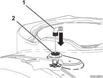
    After 100 operating hours, inspect all hoses and O–rings. Replace any damaged parts.

    Contact your Authorized Toro Dealer to obtain replacement parts.

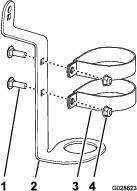
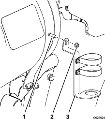
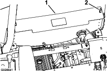
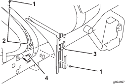
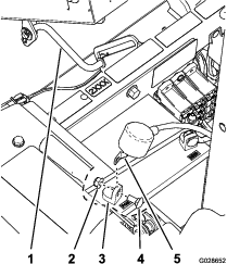
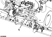
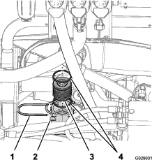
    Inspecting the Sprayer Tank Straps
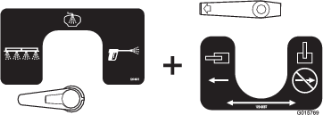
    Maintenance Service IntervalMaintenance Procedure
    After the first hour
  • Check the rinse tank straps.
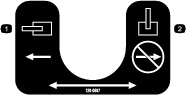
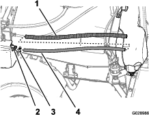
  • Important: Over-tightening the fasteners that secure the sprayer tank strap can deform and damaging of the straps.

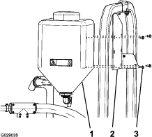
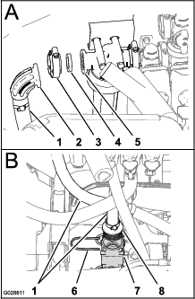
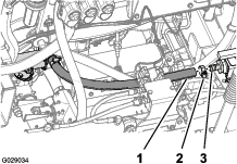
    1. Once the sprayer tank has been filled with water, check to see if there is any slack in the tank straps. If the straps are loose, tighten the fasteners at the top of the straps until they are flush with surface of the tank.

      Note: Do not over-tighten the sprayer tank straps.

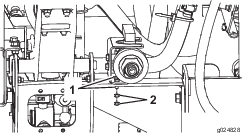
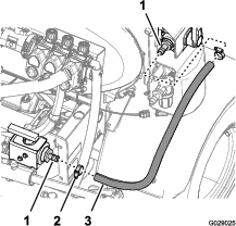
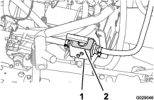
    2. Check that the right and left rinse-tank bracket hold the rinse tank securely.

      Note: Tighten the locknut that secure the rinse-tank brackets to the sprayer tank straps as needed to secure the rinse tank.