Safety
Safety and Instructional Decals
 |
Safety decals and instructions are easily visible to the operator and are located near any area of potential danger. Replace any decal that is damaged or missing. |
Installation
Installing the Rear Light
Parts needed for this procedure:
| Rear light | 1 |
| Bracket | 1 |
| Nut (5/16 inch) | 2 |
| Bolt (5/16-18 x 3/4 inch) | 2 |
| Stamped-steel nut | 2 |
-
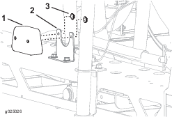
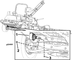
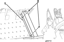
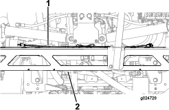
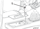
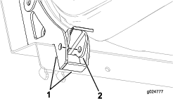
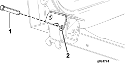
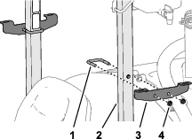
Align the holes of the rear-light bracket with the 2 holes in the boom-frame channel.
-
Secure the bracket to the frame with the 2 bolts (5/16 x 3/4 inch) and 2 locknuts (5/16 inch) as shown in Figure 1.
-
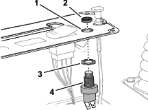
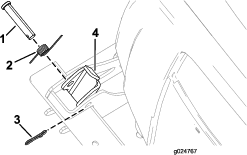
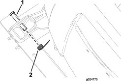
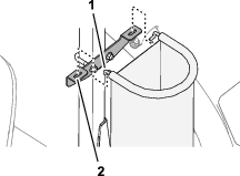
Align the rear-light assembly to the rear-light bracket and secure the assembly with the 2 stamped-steel nuts as shown in Figure 2.
Installing the Horn
Parts needed for this procedure:
| Horn assembly | 1 |
| Hex-head screw (5/16-18 x 3/4 inch) | 1 |
| Flange nut (5/16-18) | 1 |
-
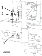
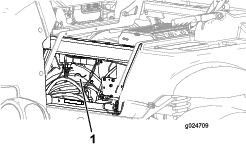
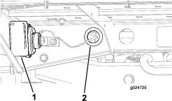
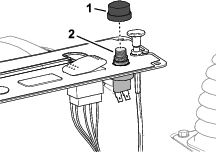
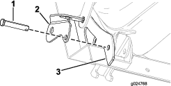
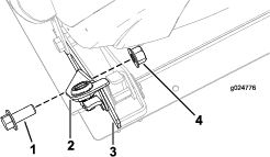
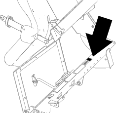
Align the horn assembly with the hole found on the front, right side of the machine (Figure 3).
-
Insert the hex-head screw (5/16-18 x 3/4 inch) through the hole of the horn assembly and the frame of the machine (Figure 3).
-
Install the horn assembly to the machine with the hex-head screw (5/16-18 x 3/4 inch) and the flange nut (5/16-18) as shown in Figure 3.
Routing the Wiring Harness
Parts needed for this procedure:
| Wire harness | 1 |
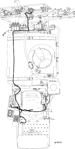
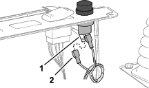
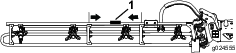
Figure 4 shows an outline of the kit wire-harness routing on the machine.
Routing the Wiring Harness to the Side Console
Routing the Wire Harness to the Horn
-
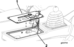
Remove the 2 bolts that secure the hose cover to the machine, and remove the cover (Figure 7 and Figure 8).
-
Route the wire harness forward and along the hoses to the horn.
-
Route the wire harness through the grommet at the hole in the rear-angle platform to the horn (Figure 9).
-
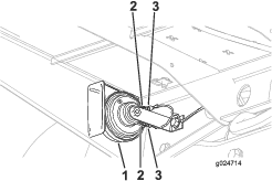
Connect the wiring-harness leg with the 2 terminals to the 2 terminals on the horn (Figure 10).
-
Install the cover removed in step 1, and secure it with the 2 bolts.
Installing the Horn Switch
Parts needed for this procedure:
| Horn switch, jam nut, and knurled nut | 1 |
| Switch button | 1 |
Removing the Control Panel
Assembling the Horn Switch
-
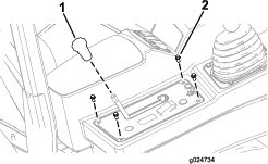
Thread the jam nut onto the body of the horn switch (Figure 16).
-
Insert the horn switch into the hole in the control-panel cover, and secure the switch with the knurled nut.
-
Thread the switch button onto the horn switch (Figure 17).
-
Connect the 2 terminals of the wire harness labeled HORN SWITCH to the terminals of the horn switch (Figure 18).
Assembling the Control Panel
-
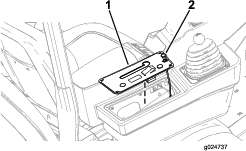
Align the control-panel cover to the side console (Figure 19).
-
Secure the control-panel cover to the side console with the 4 hex-head screws (1/4 x 1/2 inch) that you removed in Removing the Control Panel.
-
Thread the knob onto the differential-lock rod.
Installing the Seat Lock
Parts needed for this procedure:
| Lock-mount bracket | 1 |
| Latch | 1 |
| Grip | 1 |
| Hex-head screw (12 x 20 mm) | 1 |
| Locknut (12 mm) | 1 |
-
Remove the hairpin from the clevis pin (Figure 20).
-
Remove the clevis pin and spring from the latch (Figure 20).
-
Partially insert the clevis pin through the lock bracket (Figure 21).
-
Align the lock bracket and the clevis pin through the hole of the outboard-seat gusset (Figure 21).
-
Align the holes in the latch with the holes in the seat gussets (Figure 22).
-
Partially move the clevis pin inward through the hole in the seat latch (Figure 23).
-
Install the spring onto the clevis pin (Figure 24).
-
Fully insert the clevis pin through the holes in the seat latch and the inboard-seat gusset.
-
Secure the lock bracket to the outboard-seat gusset with the hex-head screw (12 x 20 mm) and the locknut (12 mm) as shown in Figure 25.
Installing the Personal Protective Equipment Storage Bags
Parts needed for this procedure:
| PPE storage bag | 2 |
| Hoop rod | 2 |
| Mount bracket | 2 |
| U-bolt | 2 |
| Flange locknut (3/8 inch) | 4 |
-
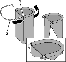
Insert a hoop rod into the sleeve of the PPE storage bag as shown in Figure 26.
-
Repeat step 1 for the other hoop and bag.
-
Install the mount bracket to the rollbar tube (Figure 27) with a U-bolt and 2 flange locknuts (3/8 inch).
Note: Ensure that the bracket location does not cover the rollbar decals.
-
Repeat step 3 at the other side of the machine.
-
Insert the hooks of the hoop rod into the slots in the mount bracket (Figure 28).
-
Repeat step 5 at the other side of the machine.
Applying the Decals to the Machine
Parts needed for this procedure:
| Boom lift-point decal | 2 |
| Tank-contents decal | 1 |
| Regulatory decal | 1 |
Applying the Boom Lift-Point Decals
-
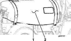
Locate the middle of an outer boom, between the brackets, as shown in Figure 29.
-
Clean the surface of the truss tube at the location that you identified in step 1, ensuring the surface is free of dirt, grease, or other foreign material.
-
Remove 1 of the decals from the backing, and adhere the decal to truss tube of the boom.
-
Repeat steps 1 through 3 at the other boom.
Applying the Tank-Contents Decal
Use the erasable surface of the decal to record the tank content.
Affix the tank-contents decal to the rollbar, directly behind the operator’s position.
Applying the Regulatory Decal
-
Clean the surface of the step below the model-serial plate and the emissions decal.
-
Remove the backing from the regulatory decal, and adhere it to the step.
-
Adhere the regulatory decal below the emissions decal.