| Maintenance Service Interval | Maintenance Procedure |
|---|---|
| Before each use or daily |
|
Introduction
This utility vehicle is intended to be primarily used off-highway to transport people and material loads. Using this product for purposes other than its intended use could prove dangerous to you and bystanders.
Read this information carefully to learn how to operate and maintain your product properly and to avoid injury and product damage. You are responsible for operating the product properly and safely.
Visit www.Toro.com for product safety and operation training materials, accessory information, help finding a dealer, or to register your product.
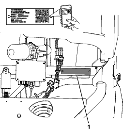
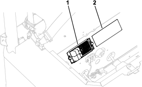
Whenever you need service, genuine Toro parts, or additional information, contact an Authorized Service Distributor or Toro Customer Service and have the model and serial numbers of your product ready.Figure 1 identifies the location of the model and serial numbers on the product. Write the numbers in the space provided.
Important: With your mobile device, you can scan the QR code on the serial number decal (if equipped) to access warranty, parts, and other product information.
This manual uses 2 words to highlight information. Important calls attention to special mechanical information and Note emphasizes general information worthy of special attention.
The safety-alert symbol (Figure 2) appears both in this manual and on the machine to identify important safety messages that you must follow to avoid accidents. This symbol will appear with the word Danger, Warning, or Caution.
-
Danger indicates an imminently hazardous situation which, if not avoided, will result in death or serious injury.
-
Warning indicates a potentially hazardous situation which, if not avoided, could result in death or serious injury.
-
Caution indicates a potentially hazardous situation which, if not avoided, may result in minor or moderate injury.

This product complies with all relevant European directives; for details, please see the separate product specific Declaration of Conformity (DOC) sheet.
It is a violation of California Public Resource Code Section 4442 or 4443 to use or operate the engine on any forest-covered, brush-covered, or grass-covered land unless the engine is equipped with a spark arrester, as defined in Section 4442, maintained in effective working order or the engine is constructed, equipped, and maintained for the prevention of fire.
The enclosed engine owner's manual is supplied for information regarding the US Environmental Protection Agency (EPA) and the California Emission Control Regulation of emission systems, maintenance, and warranty. Replacements may be ordered through the engine manufacturer.
Warning
CALIFORNIA
Proposition 65 Warning
Diesel engine exhaust and some of its constituents are known to the State of California to cause cancer, birth defects, and other reproductive harm.
Battery posts, terminals, and related accessories contain lead and lead compounds, chemicals known to the State of California to cause cancer and reproductive harm. Wash hands after handling.
Safety
This machine has been designed in accordance with the requirements of EN 16990 and SAE J2258.
General Safety
This product is capable of causing personal injury. Always follow all safety instructions to avoid serious personal injury.
-
Read and understand the contents of this Operator’s Manual before you start the machine. Ensure that everyone using this product knows how to use it and understands the warnings.
-
Carrying a heavy load with and/or adding attachments to the vehicle may affect its stability, depending on the amount and distribution of the weight.
-
Use your full attention while operating the machine. Do not engage in any activity that causes distractions; otherwise, injury or property damage may occur.
-
Do not put your hands or feet near moving components of the machine.
-
Do not operate the machine without all guards and other safety protective devices in place and working on the machine.
-
Keep bystanders and children out of the operating area. Never allow children under 16 to operate the machine unless they have obtained a state-issued motor vehicle driver’s license.
-
Stop and shut off the machine and remove the key before servicing or fueling.
Improperly using or maintaining this machine can result in injury.
To reduce the potential for injury, comply with these safety instructions
and always pay attention to the safety-alert symbol  , which means Caution, Warning,
or Danger—personal safety instruction. Failure to comply with
these instructions may result in personal injury or death.
, which means Caution, Warning,
or Danger—personal safety instruction. Failure to comply with
these instructions may result in personal injury or death.
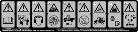
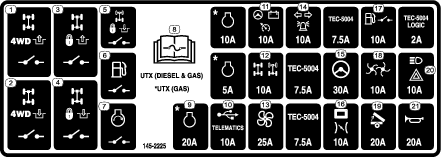
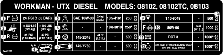
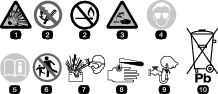
Safety and Instructional Decals
|
Safety decals and instructions are easily visible to the operator and are located near any area of potential danger. Replace any decal that is damaged or missing. |

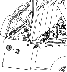
For Standard (2-Person) Models

For Crew (4-Person) Models

Setup
Note: Determine the left and right side of the machine from the normal operating position.
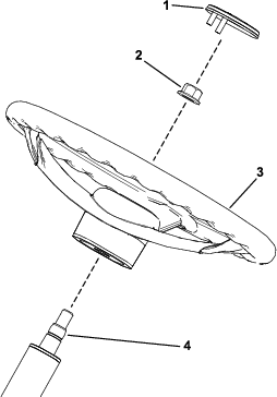
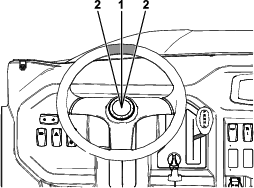
Installing the Steering Wheel
TC Models Only
Parts needed for this procedure:
| Steering wheel | 1 |
| Cover | 1 |
-
If the cover is installed, remove it from the hub of the steering wheel.
-
Remove the locknut (1/2 inch) from the steering shaft.
-
Ensure that the front wheels are centered.
-
Slide the steering wheel onto the steering shaft.
-
Secure the steering wheel to the shaft using the previously removed locknut (1/2 inch) and tighten it to 24 to 30 N∙m (18 to 22 ft-lb).
-
Install the cover onto the steering wheel.
Connecting the Battery
TC Models Only
Warning
Incorrect battery cable routing could damage the machine and cables, causing sparks. Sparks can cause the battery gases to explode, resulting in personal injury.
-
Always disconnect the negative (black) battery cable before disconnecting the positive (red) cable.
-
Always connect the positive (red) battery cable before connecting the negative (black) cable.
-
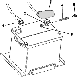
Connect the positive battery cable (red) to the positive (+) terminal of the battery and secure the cable using the bolt and nuts (Figure 4).
-
Slide the insulator boot over the positive terminal (Figure 4).
Note: The insulator boot prevents a possible short-to-ground from occurring.
-
Connect the negative battery cable (black) to the negative (–) terminal of the battery and secure the cable using the bolt and nuts (Figure 4).
Changing the Blinker Mode from United States (US) to European (EU)
International Models Only
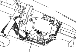
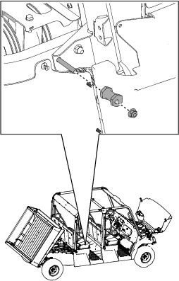
Disconnect the default US jumper connection located underneath the hood (Figure 5).
Note: Use a cable tie to secure the loose connection.
Converting the Speedometer from mph to km/h
-
Shift the transmission lever to the P (PARK) position.
-
Rotate the key switch to the ON position.
-
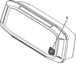
Press and hold the display button between 3 to 10 seconds to convert the speedometer from mph to km/h.
Checking the Fluid Levels and Tire Pressure
-
Check the engine-oil level before you first start the engine; refer to Checking the Engine-Oil Level.
-
Check the transaxle-fluid level before you first start the engine; refer to Checking the Transaxle-Fluid Level.
-
Check the front differential oil level before you first start the engine; refer to Checking the Front Differential Oil Level.
-
Check the engine-coolant level before you first start the engine; refer to Checking the Engine-Coolant Level.
-
Check the brake-fluid level before you first start the engine; refer to Checking the Brake-Fluid Level.
-
Check the air pressure in the tires; refer to Checking the Tire Pressure.
Installing the Rollover Protection System (ROPS)
For Standard (2-Person) Models
Parts needed for this procedure:
| Left, front roll bar assembly | 1 |
| Right, front roll bar assembly | 1 |
| Left, rear roll bar assembly | 1 |
| Right, rear roll bar assembly | 1 |
| Front crosslink | 1 |
| Rear crosslink | 1 |
| Seat panel | 1 |
| Shoulder restraint | 2 |
| Hex-head bolt (3/8 x 1-1/4 inches) | 8 |
| Carriage bolt (5/16 x 3/4 inch) | 12 |
| Hex-washer head bolt (5/16 x 3/4 inch) | 4 |
| Hex-washer head bolt (1/4 x 3/4 inch) | 10 |
| Hex-washer head bolt (1/4 x 1 inch) | 2 |
| Button-head bolt (5/16 x 1-1/2 inches) | 2 |
| Flange-head bolt (3/8 x 2-1/4 inches) | 2 |
| Locknut (5/16 inch) | 14 |
| Locknut (3/8 inch) | 10 |
| Locknut (1/4 inch) | 2 |
| Locknut (7/16 inch) | 2 |
-
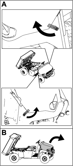
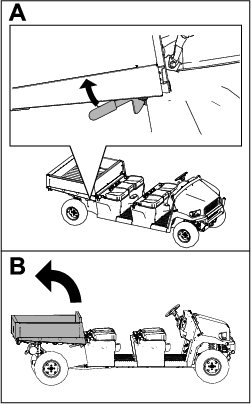
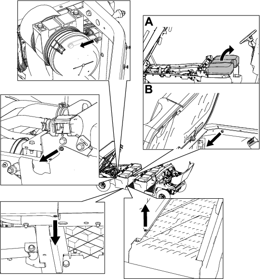
Raise the cargo bed (Figure 7).
-
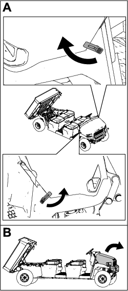
Raise the hood (Figure 8).
-
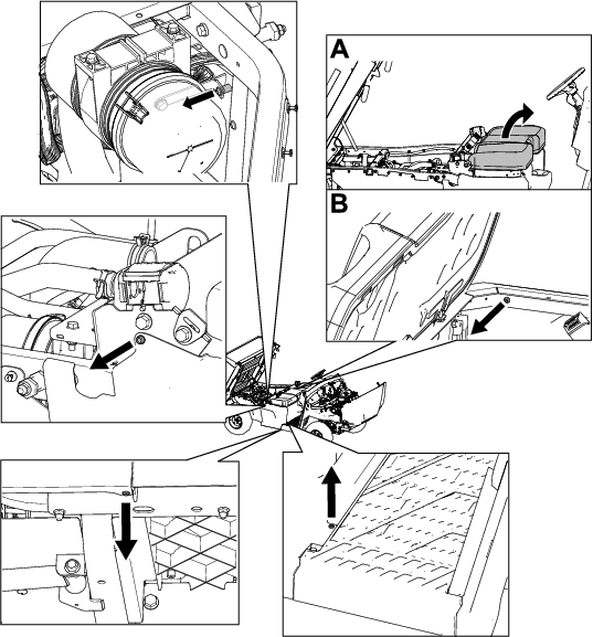
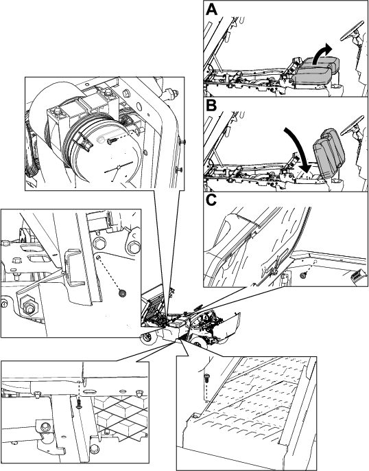
Remove the hex-washer head bolts (1/4 x 3/4 inch) and T30 torx-head fasteners from the right and left seat-base panels (Figure 9).
Remove the fuel-tank cap from the left seat-base panel (Figure 10).
Note: Do not pull the cap out until you reach the end of the tether.
-
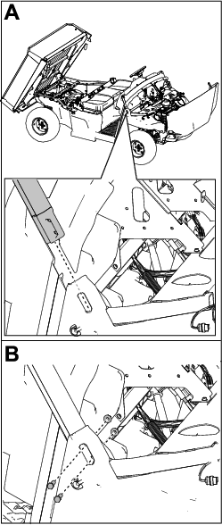
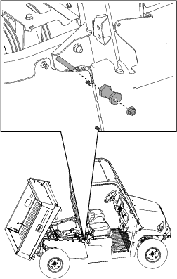
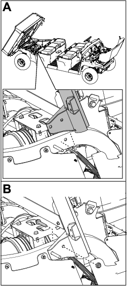
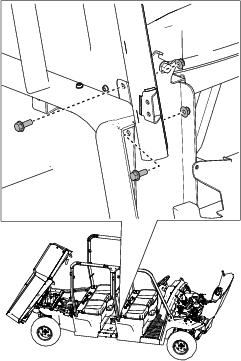
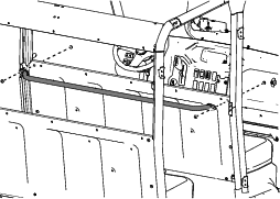
Remove the locknut (3/8 inch) and latch pin from the right and left, rear frame tubes (Figure 11).

-
Loosely secure the right, rear roll bar assembly to the right, rear frame tube using 1 flange-head bolt (3/8 x 2-1/4 inches) and 1 locknut (3/8 inch) as shown in Figure 12.
-
Repeat steps 5 through 7 for the left, rear roll bar assembly.
-
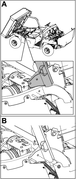
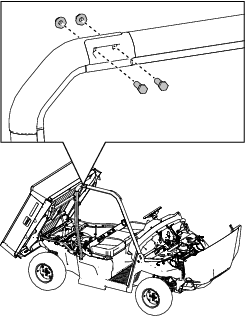
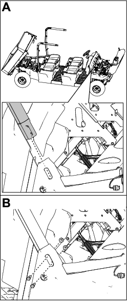
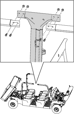
Loosely secure the right, front roll bar assembly to the right roll bar mount bracket using 2 hex-head bolts (3/8 x 1-1/4 inches) and 2 locknuts (3/8 inch) as shown in Figure 13.
-
Loosely secure the right, front roll bar assembly to the right, rear roll bar assembly using 2 hex-head bolts (3/8 x 1-1/4 inches) and 2 locknuts (3/8 inch) as shown in Figure 14.
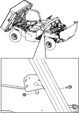
-
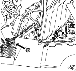
Loosely secure the right, front roll bar assembly to the dash panel using 1 hex-washer head bolt (1/4 x 1 inch) and 1 locknut (1/4 inch) as shown in Figure 15.
-
Repeat steps 10 through 13 for the left, front roll bar assembly.
-
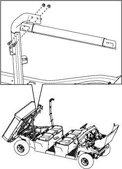
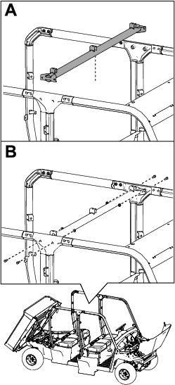
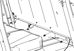
Secure the front crosslink to the front roll bar assemblies using 4 carriage bolts (5/16 x 3/4 inch) and 4 locknuts (5/16 inch) as shown in Figure 16.
-
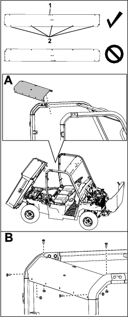
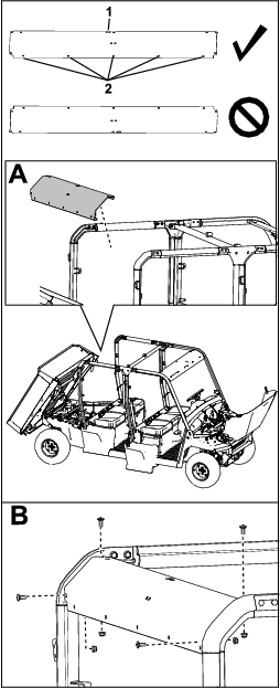
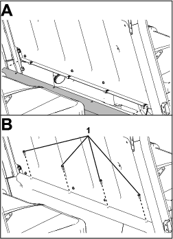
Secure the rear crosslink to the rear roll bar assemblies using 4 carriage bolts (5/16 x 3/4 inch) and 4 locknuts (5/16 inch) as shown in Figure 17.
Ensure that you position the crosslink as shown in Figure 17.
-
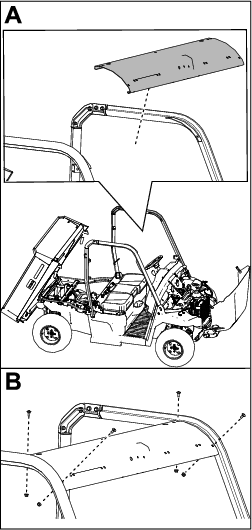
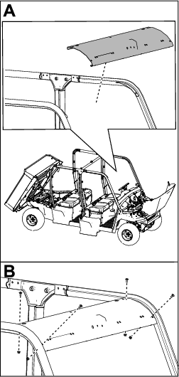
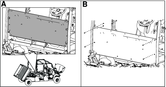
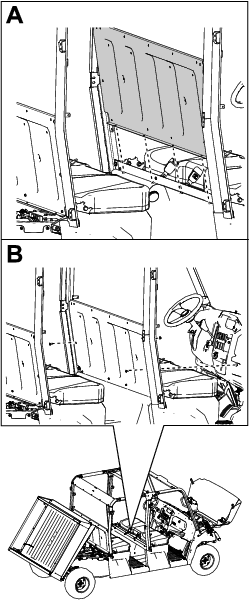
Secure the seat panel to the rear roll bar assemblies using 4 carriage bolts (5/16 x 3/4 inch) and 4 locknuts (5/16 inch) as shown in Figure 18.
-
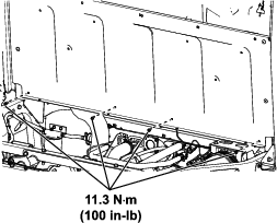
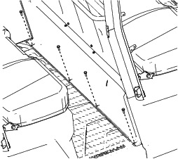
Secure the seat panel to the rear frame crosslink channel using 4 hex-washer head bolts (1/4 x 3/4 inch) as shown in Figure 19.

-
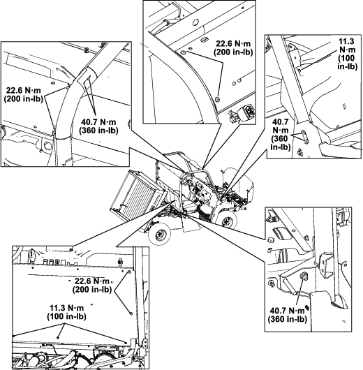
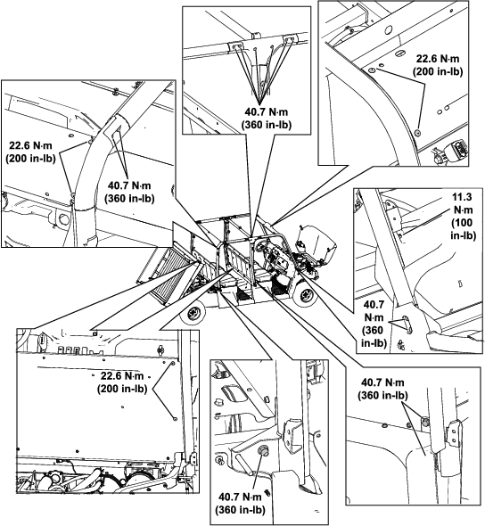
Torque the fasteners to the specifications shown in Figure 20.
-
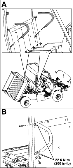
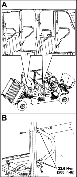
Secure the 2 shoulder restraints to the rear roll bar assemblies using 4 self-tapping screws (5/16 x 3/4 inch), 2 button-head bolts (5/16 x 1-1/2 inches), and 2 locknuts (5/16 inch) as shown in Figure 21.
Torque the locknuts (5/16 inch) to 22.6 N∙m (200 in-lb) as shown in Figure 21.
-
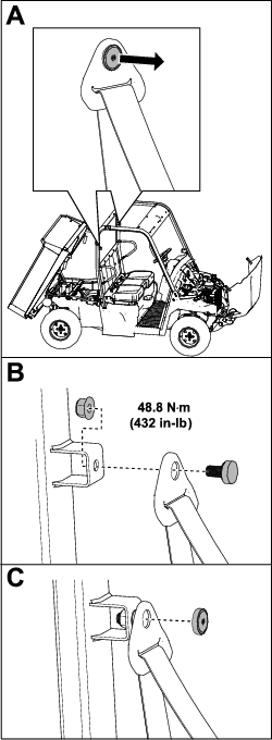
Secure the right seat belt as follows:
-
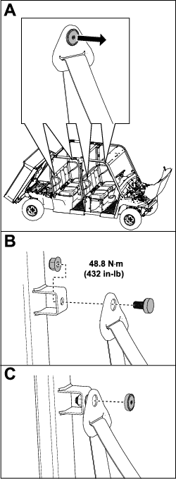
Remove the cap from the top portion of the seat belt (Figure 22).
-
Insert seat belt into the roll bar seat belt bracket and secure the seat belt using a locknut (7/16 inch) as shown in Figure 22.
Torque the locknut (7/16 inch) to 48.8 N∙m (432 in-lb) as shown in Figure 22.
-
Install the cap (Figure 22).
-
Repeat these steps for the left seat belt.
-
-
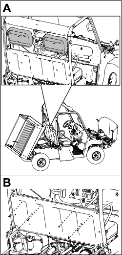
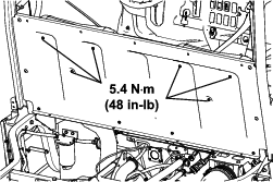
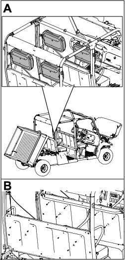
Secure the 2 seat backs to the seat panel using 6 hex-washer head bolts (1/4 x 3/4 inch) as shown in Figure 23.
-
Torque the 6 hex-washer head bolts (1/4 x 3/4 inch) to 5.4 N∙m (48 in-lb) as shown in Figure 24.
-
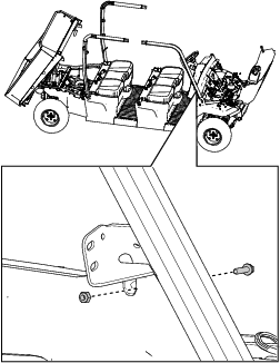
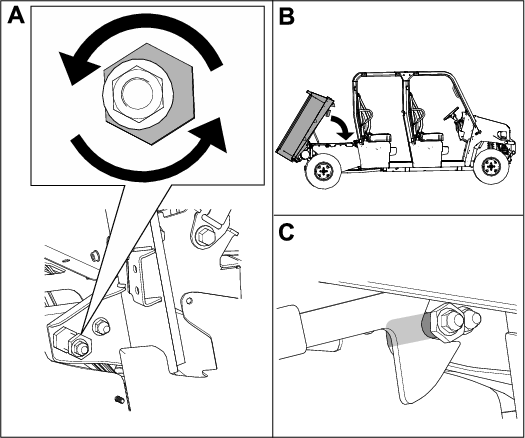
Install the previously removed locknuts (3/8 inch) and latch pins to the right and left, rear frame tubes (Figure 25).
-
Adjust the alignment nut for the cargo bed latch until you close the gap and the cargo bed latches securely (Figure 26).
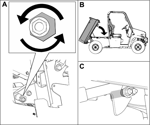
-
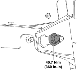
Torque the locknut (3/8 inch) to 40.7 N∙m (360 in-lb) as shown in Figure 27.

-
Secure the right and left seat-base panels using the previously removed hex-washer head bolts (1/4 x 3/4 inch) as shown in Figure 28.
-
Install the fuel-tank cap to the left seat-base panel (Figure 29).

Installing the Rollover Protection System (ROPS)
For Crew (4-Person) Models
Parts needed for this procedure:
| Left, front roll bar assembly | 1 |
| Right, front roll bar assembly | 1 |
| Left, rear roll bar assembly | 1 |
| Right, rear roll bar assembly | 1 |
| Left, middle roll bar assembly | 1 |
| Right, middle roll bar assembly | 1 |
| Roll bar connector assembly | 2 |
| Rear seat handle assembly | 1 |
| Front crosslink | 1 |
| Middle crosslink | 1 |
| Rear crosslink | 1 |
| Seat panel | 2 |
| Shoulder restraint | 4 |
| Hex-head bolt (3/8 x 1-1/4 inches) | 20 |
| Carriage bolt (5/16 x 3/4 inch) | 16 |
| Hex-washer head bolt (5/16 x 3/4 inch) | 8 |
| Hex-washer head bolt (1/4 x 3/4 inch) | 24 |
| Hex-washer head bolt (1/4 x 1 inch) | 2 |
| Button-head bolt (5/16 x 1-1/2 inches) | 4 |
| Flange-head bolt (3/8 x 2-1/4 inches) | 2 |
| Flange-head bolt (3/8 x 1 inch) | 4 |
| Locknut (5/16 inch) | 20 |
| Locknut (3/8 inch) | 26 |
| Locknut (1/4 inch) | 2 |
| Locknut (7/16 inch) | 4 |
| Clip (1/4 inch) | 4 |
-
Raise the cargo bed (Figure 30).
-
Raise the hood (Figure 31).
-
Remove the hex-washer head bolts (1/4 x 3/4 inch) and T30 torx-head fasteners from the 2 right and 2 left seat-base panels (Figure 32).
Remove the fuel-tank cap from the left, rear seat-base panel (Figure 33).
Note: Do not pull the cap out until you reach the end of the tether.
-
Remove the 4 hex-washer head bolts (5/16 x 1 inch) securing the foot well and remove the foot well (Figure 34).
-
Remove the locknut (3/8 inch) and latch pin from the right and left, rear frame tubes (Figure 35).
-
Loosely secure the right, rear roll bar assembly to the right, rear frame tube using 1 flange-head bolt (3/8 x 2-1/4 inches) and 1 locknut (3/8 inch) as shown in Figure 36.
-
Repeat step 8 on the left side.
-
Loosely secure the right roll bar connector assembly to the right, rear roll bar assembly using 2 hex-head bolts (3/8 x 1-1/4 inches) and 2 locknuts (3/8 inch) as shown in Figure 37.
-
Repeat step 11 on the left side.
-
Loosely secure the right, front roll bar assembly to the right roll bar mount bracket using 2 hex-head bolts (3/8 x 1-1/4 inches) and 2 locknuts (3/8 inch) as shown in Figure 38.
-
Loosely secure the right, front roll bar assembly to the dash panel using 1 hex-washer head bolt (1/4 x 1 inch) and 1 locknut (1/4 inch) as shown in Figure 39.
-
Loosely secure the top of the right, middle roll bar assembly to the right, front and rear roll bar assemblies using 4 hex-head bolts (3/8 x 1-1/4 inches) and 4 locknuts (3/8 inch) as shown in Figure 40.
-
Loosely secure the bottom of the right, middle roll bar assembly to the seat base assembly using 2 flange-head bolts (3/8 x 1 inch) 2 locknuts (3/8 inch) as shown in Figure 41.
-
Repeat steps 14 through 20 on the left side.
-
Secure the front crosslink to the front roll bar assemblies using 4 carriage bolts (5/16 x 3/4 inch) and 4 locknuts (5/16 inch) as shown in Figure 42.
-
Secure the middle crosslink to the middle roll bar assemblies using 4 hex-head bolts (3/8 x 1-1/4 inches) and 4 locknuts (3/8 inch) as shown in Figure 43.
-
Secure the rear crosslink to the rear roll bar assemblies using 4 carriage bolts (5/16 x 3/4 inch) and 4 locknuts (5/16 inch) as shown in Figure 44.
Ensure that you position the crosslink as shown in Figure 44.
-
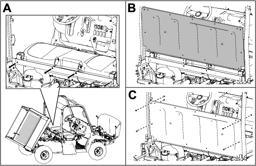
Loosely secure a seat panel to the rear roll bar assemblies using 4 carriage bolts (5/16 x 3/4 inch) and 4 locknuts (5/16 inch) as shown in Figure 45.
-
Secure a seat panel to the rear frame crosslink channel using 4 hex-washer head bolts (1/4 x 3/4 inch) as shown in Figure 46.
Torque the 4 hex-washer head bolts (1/4 x 3/4 inch) to 11.3 N∙m (100 in-lb).
-
Loosely secure the middle portion of the seat panel to the middle roll bar assemblies using 2 carriage bolts (5/16 x 3/4 inch) and 2 locknuts (5/16 inch) as shown in Figure 47.
-
Loosely secure the rear seat handle assembly to the middle seat panel using 2 carriage bolts (5/16 x 3/4 inch) and 2 locknuts (5/16 inch) as shown in Figure 48.
-
Install the 4 clips (1/4 inch) to the middle seat panel (Figure 49).
-
Secure the middle seat panel to the foot well and 4 clips (1/4 inch) using 4 hex-washer head bolts (1/4 x 3/4 inch) as shown in Figure 50.
Torque the 4 hex-washer head bolts (1/4 x 3/4 inch) to 11.3 N∙m (100 in-lb).
-
Secure the bottom of the foot well using the previously removed 4 hex-washer head bolts (5/16 x 1 inch) as shown in Figure 51.
-
Torque the fasteners to the specifications shown in Figure 52.
-
Secure the 4 shoulder restraints to the rear roll bar assemblies and middle roll bar assemblies using 8 self-tapping screws (5/16 x 3/4 inch), 4 button-head bolts (5/16 x 1-1/2 inches), and 4 locknuts (5/16 inch) as shown in Figure 53.
Torque the locknuts (5/16 inch) to 22.6 N∙m (200 in-lb) as shown in Figure 53.
-
Secure the right seat belts as follows:
-
Remove the cap from the top portion of the seat belt (Figure 54).
-
Insert seat belt into the roll bar seat belt bracket and secure the seat belt using a locknut (7/16 inch) as shown in Figure 54.
Torque the locknut (7/16 inch) to 48.8 N∙m (432 in-lb) as shown in Figure 54.
-
Install the cap (Figure 54).
-
Repeat these steps for the left seat belts.
-
-
Secure the 4 seat backs to the seat panels using 12 hex-washer head bolts (1/4 x 3/4 inch) as shown in Figure 55.
Torque the 12 hex-washer head bolts (1/4 x 3/4 inch) to 5.4 N∙m (48 in-lb).
-
Install the previously removed locknuts (3/8 inch) and latch pins to the right and left, rear frame tubes (Figure 56).
-
Adjust the alignment nut for the cargo bed latch until you close the gap and the cargo bed latches securely (Figure 57).
-
Torque the locknut (3/8 inch) to 40.7 N∙m (360 in-lb) as shown in Figure 58.
-
Secure the 2 right and 2 left seat-base panels using the previously removed hex-washer head bolts (1/4 x 3/4 inch) as shown in Figure 59.
-
Install the fuel-tank cap to the left, rear seat-base panel (Figure 60).
Burnishing the Brakes
To ensure optimum performance of the brake system, burnish the brakes before use.
-
Bring the machine up to full speed, apply the brakes to rapidly stop the machine without locking up the tires.
-
Repeat this procedure 10 times, waiting 1 minute between stops, to avoid overheating the brakes.
Product Overview
Become familiar with all the controls before you start the engine and operate the machine.
Control Panel
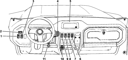
Key Switch
Use the key switch (Figure 61) to start and shut off the engine. To shut off the engine, rotate the key switch counterclockwise to the OFF position.
The key switch has 3 positions: OFF, RUN, and START. Rotate the key switch clockwise to the START position to engage the starter motor. Release the key switch when the engine starts. The key switch moves automatically to the ON position.
Headlight Switch
Push the headlight switch (Figure 61) up to turn on the headlights or down to turn off the headlights.
Turn-Signal Switch
Press the left side of the turn-signal switch (Figure 61) to activate the left-turn signal and the right side of the switch to activate the right-turn signal.
Note: The center position is off.
Hazard-Light Switch
Press the hazard-light switch (Figure 61) up to turn on the hazard lights or down to turn off the hazard lights.
Cruise Control Switch
Press the cruise control switch (Figure 61) up to set the desired drive speed; refer to Using the Cruise Control.
Differential-Lock Switch
Use the differential-lock switch (Figure 61) to engage or disengage the front and/or rear differentials; refer to Using the 4-Wheel Drive/Differential Lock(s).
2-Wheel Drive/4-Wheel Drive Switch
Use the 2-wheel drive/4-wheel drive switch (Figure 61) to toggle between 2-wheel drive and 4-wheel drive; refer to Using the 4-Wheel Drive/Differential Lock(s)
Horn Switch
Press the horn switch (Figure 61) to sound the horn.
USB Power Point
Use the power point (Figure 61) to power mobile devices.
Gear Selector
Use the gear selector (Figure 61) to shift the transmission between (PARK), (REVERSE), (NEUTRAL), H(HIGH FORWARD), and (LOW FORWARD) ground operation.
Important: Do not shift the transmission to the REVERSE, HIGH, or LOW gear unless the machine is motionless and the engine is at low-idle; otherwise, you could damage the transmission.
Display
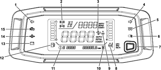
Turn-Signal Indicators
The left or right turn-signal blinks when you press the turn-signal switch to the left or right (Figure 62).
2-Wheel Drive/4-Wheel Drive/Differential Lock Indicator
Note: When the indicator (Figure 62) is blinking it means that the setting is not engaged/inactive; when it becomes solid, it is engaged/active.
Refer to Figure 63 and the corresponding table for using the 2-wheel drive/4-wheel drive switch and differential lock switch together.
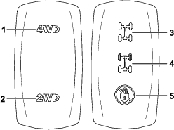
| 2-Wheel Drive/4-Wheel Drive Switch Position | Differential Lock Switch Position | Result |
| 2 | 5 | No indicator |
| 2 | 4 |  |
| 2 | 3 |  (blinking—inactive configuration) (blinking—inactive configuration) |
| 1 | 5 |  |
| 1 | 4 |  |
| 1 | 3 | |
Cruise Control/Speed-Limited Indicator
If the cruise control is set, the indicator illuminates (Figure 62).
If the top speed of the machine is limited, the indicator illuminates. The speed is limited if the following occurs:
-
The cruise control is set.
-
There is a fault code.
-
A seat belt is not buckled.
Glow-Plug Indicator Light
The glow-plug indicator light (Figure 62) illuminates when you turn the key switch to the ON position and the glow plug is activated.
When the glow-plug indicator light turns off (approximately 5 to 10 seconds), you may start the engine.
Headlights Indicator
The headlights indicator illuminates when the headlights are in the ON position.
Seat Belt Indicator
The seat belt indicator illuminates when the operator does not have their seat belt fastened.
Note: If the seat belt is not fastened, the machine speed will be limited.
Fault Code Indicator
The fault code indicator illuminates and the corresponding fault code number appears when a machine fault occurs.
Important: Do not operate the machine if a fault code appears; otherwise, serious damage could occur. Contact your authorized Toro distributor.
Hour Meter
The hour meter indicates the total hours of machine operation. The hour meter (Figure 62) starts to function whenever the engine is running.
Note: To obtain the odometer reading, contact your authorized Toro distributor.
Oil-Pressure-Warning Light
The oil-pressure-warning light (Figure 62) illuminates if the engine-oil pressure drops below a safe level while the engine is running.
Important: If the light flickers or remains on, stop the machine, shut off the engine, and check the oil level. If the oil level is low, but adding oil does not cause the light to go out when the engine is started, shut off the engine immediately, and contact your authorized Toro distributor. for assistance.
Check the operation of the warning light as follows:
-
Ensure that the machine is in the P (PARK) position.
-
Turn the key switch to the ON/PREHEAT position, but do not start the engine.
Note: The oil-pressure light should illuminate. If the light does not turn on, then there is a potential malfunction in the display and/or signal.
Note: If you just started or shut off the engine, it may take a few seconds for the light to turn off or on.
Coolant-Temperature Gauge and Light
The coolant-temperature gauge registers the coolant temperature in the engine and operates only when the key switch is in the ON position (Figure 62).
The 8 coolant bars blink and a fault code appears if the engine overheats.
Charge Indicator
The charge indicator illuminates when the battery discharges. If the light illuminates during operation, stop the machine, shut off the engine, and check for possible causes, such as the alternator belt (Figure 62).
Important: If the alternator belt is loose or broken, do not operate the machine until the adjustment or repair is complete. Failure to observe this precaution may damage the engine.
Check the operation of the warning lights as follows:
-
Shift the transmission lever to the P (PARK) position.
-
Turn the key switch to the ON/PREHEAT position, but do not start the engine. The coolant temperature, charge indicator, and oil-pressure lights should glow. If any light does not function, there is a malfunction in the system that you must repair.
Fuel Gauge
The fuel gauge shows the amount of fuel in the tank. It displays only when key switch is in the ON position (Figure 62).
A single bar indicates a low fuel level and 1 flashing bar indicates that the fuel tank is nearly empty.
Tachometer
The tachometer displays the speed of the engine (Figure 62).
Speedometer
The speedometer registers the ground speed of the machine (Figure 62).
Display Button/Ground Speed Governor Control
Press the button (Figure 62) between 0 to 3 seconds to swap the locations of tachometer and speedometer.
Press and hold the button (Figure 62) between 3 to 10 seconds to convert the speedometer from mph to km/h.
Press and hold the button for 10 seconds or more to adjust the ground speed governor; refer to Adjusting the Ground Speed Governor.
Check-Engine Light
The check-engine light illuminates to indicate an engine malfunction; refer to .
Accelerator Pedal
Use the accelerator pedal (Figure 64) to vary the ground speed of the machine when the transmission is in gear. Pressing down the accelerator pedal increases the engine speed and ground speed. Releasing the pedal decreases the engine speed and ground speed.
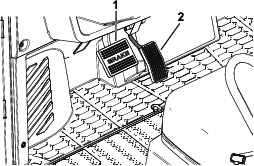
Brake Pedal
Use the brake pedal to stop or slow the machine (Figure 64).
Caution
Operating a machine with worn or incorrectly-bled brakes may result in personal injury.
If the brake pedal travels to within 25 mm (1 inch) of the machine floor board, bleed and/or repair the brakes.
Note: Specifications and design are subject to change without notice.
| Overall width | 154 cm (60-1/2 inches) |
| Overall length | Model 08102: 314 cm (123-1/2 inches) |
| Model 08102TC: 314 cm (123-1/2 inches) | |
| Model 08103: 405 cm (159-1/2 inches) | |
| Base weight (dry) | Model 08102: 884 kg (1,949 lb) |
| Model 08102TC: 884 kg (1,949 lb) | |
| Model 08103: 994 kg (2,191 lb) | |
| Maximum gross vehicle weight (GVW) on level ground, including the base weight | 1814 kg (4,000 lb) |
| Maximum cargo bed capacity (on level ground) total | Model 08102: 567 kg (1,250 lb) |
| Model 08102TC: 567 kg (1,250 lb) | |
| Model 08103: 454 kg (1,000 lb) | |
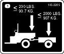
| Tow capacity | Tongue weight: 91 kg (200 lb) |
| Maximum trailer weight: 907 kg (2,000 lb) | |
| Ground clearance | 23 cm (9 inches) with no load or operator |
| Wheel base | Model 08102: 203 cm (80 inches) |
| Model 08102TC: 203 cm (80 inches) | |
| Model 08103: 295 cm (116 inches) | |
| Height | 201 cm (79 inches) to top of ROPS |
| Cargo bed length | Inside: 113 cm (44-1/2 inches) |
| Outside: 127 cm (50 inches) | |
| Cargo bed width | Inside: 142 cm (56 inches) |
| Outside: 151 cm (59-1/2 inches) | |
| Cargo bed inside height | 28 cm (11 inches) |
| Engine speed | Low idle: 1,200 to 1,300 rpm |
| High idle: 3,790 to 3,890 rpm |
Attachments/Accessories
A selection of Toro approved attachments and accessories is available for use with the machine to enhance and expand its capabilities. Contact your Authorized Service Dealer or authorized Toro distributor or go to www.Toro.com for a list of all approved attachments and accessories.
To ensure optimum performance and continued safety certification of the machine, use only genuine Toro replacement parts and accessories. Replacement parts and accessories made by other manufacturers could be dangerous, and such use could void the product warranty.
Operation
Before Operation
Before Operation Safety
General Safety
-
This vehicle is not a toy. Never allow children under 16 (unless they have obtained a state-issued motor vehicle driver’s license) or people who are not trained or physically capable to safely operate or service the machine. Local regulations may restrict the age of the operator. The owner is responsible for training all operators and mechanics.
-
Become familiar with the safe operation of the equipment, operator controls, and safety signs.
-
Shut off the machine, remove the key, and wait for all movement to stop before you leave the operator’s position. Allow the machine to cool before adjusting, servicing, cleaning, or storing it.
-
Know how to stop and shut off the machine quickly.
-
Ensure that there are not more occupants (you and your passenger(s)) than the number of handholds equipped on the machine. Do not carry small children on a person's lap.
-
Ensure that all passengers understand and follow the instructions and warnings in the Operator's Manual.
-
Check that all safety devices and decals are in place. Repair or replace all safety devices and replace all illegible or missing decals. Do not operate the machine unless they are present and functioning properly.
Fuel Safety
-
Use extreme care in handling fuel. It is flammable and its vapors are explosive.
-
Extinguish all cigarettes, cigars, pipes, and other sources of ignition.
-
Use only an approved fuel container.
-
Do not remove the fuel cap or fill the fuel tank while the engine is running or hot.
-
Do not add or drain fuel in an enclosed space.
-
Do not store the machine or fuel container where there is an open flame, spark, or pilot light, such as on a water heater or other appliance.
-
If you spill fuel, do not attempt to start the engine; avoid creating any source of ignition until the fuel vapors have dissipated.
Performing Daily Maintenance
Before starting the machine each day, perform the Each Use/Daily procedures listed in .
Checking the Tire Pressure
| Maintenance Service Interval | Maintenance Procedure |
|---|---|
| Before each use or daily |
|
Danger
Low tire pressure decreases the side-hill stability of the machine. This could cause a rollover, which may result in personal injury or death.
Do not under-inflate the tires.
Front tire pressure specification: 165 kPa (24 psi)
Rear tire pressure specification with a cargo load of 227 kg (500 lb) or less: 165 kPa (24 psi)
Rear tire pressure specification with a cargo load of more than 227 kg (500 lb): 207 kPa (30 psi)
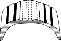
Important: Check the tire pressure frequently to ensure proper inflation. If the tires are not inflated to the correct pressure, the tires will wear prematurely and may cause the 4-wheel drive to bind.
Figure 65 shows an example of tire wear caused by under-inflation.
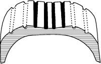
Figure 66 shows an example of tire wear caused by over-inflation.
Adding Fuel
Recommended Fuel
The engine runs on clean, fresh diesel fuel with a minimum cetane rating of 40. Purchase fuel in quantities that you can use within 30 days to ensure fuel freshness.
Use summer-grade diesel fuel (No. 2-D) at temperatures above -7°C (20°F) and winter grade diesel fuel (No. 1-D or No. 1-D/2-D blend) below -7°C (20°F). Use of winter-grade diesel fuel at lower temperatures provides lower flash point and pour point characteristics, allowing easier starts and lessening the chances of chemical separation of the fuel due to lower temperatures.
Using summer-grade diesel fuel above -7°C (20°F) contributes toward longer life of the fuel-pump components.
Important: Never use kerosene or gasoline in place of diesel fuel. Failure to observe this caution will damage the engine.
Filling the Fuel Tank
Fuel-tank capacity: 32 L (8.5 US gallons)
-
Clean the area around the fuel-tank cap.
-
Remove the fuel-tank cap.
-
Fill the tank to approximately 25 mm (1 inch) below the bottom of the filler neck and install the cap.
Note: Do not overfill the fuel tank.
-
Install the fuel-tank cap securely.
-
Wipe up any spilled fuel.
Breaking in a New Machine
During the first 50 hours, perform the following guidelines to provide proper performance for the machine:
-
After starting a cold engine, let it warm up for about 15 seconds before using the machine.
Note: Allow more time for the engine to warm up when operating in cold temperatures.
-
After using the machine, allow the engine to cool down for about 15 seconds before shutting the engine off.
-
Ensure that the brakes are burnished; refer to Burnishing the Brakes.
-
Check the fluid levels more often during this process.
-
Vary the machine speed during operation and avoid fast accelerations.
-
A break-in oil for the engine is not required. Original engine oil is the same type specified for regular oil changes.
During Operation
During Operation Safety
General Safety
-
The owner/operator can prevent and is responsible for accidents that may cause personal injury or property damage.
-
Passengers should sit in the designated seating positions only. Do not carry passengers in the cargo bed. Keep bystanders and children out of the operating area.
-
Wear appropriate clothing, including eye protection; long pants; substantial, slip-resistant footwear; and hearing protection. Tie back long hair and do not wear loose clothing or loose jewelry.
-
Wear an approved helmet whenever you operate the machine on rough or uneven terrain or at high speeds.
-
Use your full attention while operating the machine. Do not engage in any activity that causes distractions; otherwise, injury or property damage may occur.
-
Do not operate the machine while ill, tired, or under the influence of alcohol or drugs.
-
Operate the machine outdoors or in a well-ventilated area only.
-
Do not exceed the maximum gross vehicle weight (GVW) of the machine.
-
Use extra caution when operating, braking, or turning the machine with a heavy load in the cargo bed.
-
Carrying oversized loads in the cargo bed reduces the stability of the machine. Do not exceed the carrying capacity of the bed.
-
Carrying material that cannot be bound to the machine adversely affects the steering, braking, and stability of the machine. When you carry material that cannot be bound to the machine, use caution when steering or braking.
-
Carry a reduced load and reduce the ground speed of the machine when operating on rough, uneven terrain, and near curbs, holes, and other sudden changes in terrain. Loads may shift, causing the machine to become unstable.
-
Before you start the machine, ensure that the transmission is in neutral, the parking brake is engaged, and you are in the operating position.
-
You and your passengers should remain seated whenever the machine is moving. Keep your hands on the steering wheel; your passengers should use the handholds provided. Keep arms and legs within the machine body at all times.
-
Operate the machine only in good visibility. Watch for holes, ruts, bumps, rocks, or other hidden objects. Uneven terrain could overturn the machine. Tall grass can hide obstacles. Use care when approaching blind corners, shrubs, trees, or other objects that may obscure your vision.
-
Do not drive the machine near drop-offs, ditches, or embankments. The machine could suddenly roll over if a wheel goes over the edge or if the edge gives way.
-
Always watch out for and avoid low overhangs such as tree limbs, door jambs, overhead walkways, etc.
-
Look behind and down before reversing the machine to be sure of a clear path.
-
This machine was not designed or intended to be used on public roadways. Doing so may be hazardous and in violation of local laws.
-
When using the machine on public roads, follow all traffic regulations and use any additional accessories that may be required by law, such as lights, turn signals, slow-moving vehicle (SMV) signs, and others as required.
-
If the machine ever vibrates abnormally, stop and shut off the machine immediately, wait for all movement to stop, and inspect for damage. Repair all damage to the machine before resuming operation.
-
It can take longer to stop the machine on wet surfaces than on dry surfaces. To dry out wet brakes, drive slowly on a level surface while putting light pressure on the brake pedal.
-
Operating the machine on a paved surface in different modes, such as 2-wheel drive and 4-wheel drive, and carrying passengers and cargo may affect the handling of the machine.
-
Operating the machine at high speed and then quickly stopping may cause the rear wheels to lock up, which impairs your control of the machine.
-
Improperly driving and/or making abrupt maneuvers while driving at fast speed increases the risk of a tip-over or rollover.
-
Do not touch the engine, transmission, muffler, or exhaust manifold while the engine is running, or soon after you shut off the engine, because these areas may be hot enough to cause burns.
-
Do not leave a running machine unattended.
-
Before you leave the operating position, do the following:
-
Park the machine on a level surface.
-
Shift the transmission lever to the P (PARK) position.
-
Shut off the machine and remove the key.
-
Wait for all movement to stop.
-
-
Do not operate the machine when there is the risk of lightning.
-
Use accessories and attachments approved by The Toro® Company only.
Rollover Protection System (ROPS) Safety
-
The ROPS is an integral safety device. Do not remove the ROPS from the machine.
-
Always wear your seat belt to prevent/minimize injury to you and your passenger(s) in the event of an accident; ensure that it is attached and that you can release it quickly in an emergency.
-
Check carefully for overhead obstructions and do not contact them.
-
Keep the ROPS in safe operating condition by thoroughly inspecting it periodically for damage and keeping all the mounting fasteners tight.
-
Replace damaged ROPS components. Do not repair or alter them.
Multi-Passenger Safety
-
Do not exceed the gross vehicle weight (GVW) of the machine. You must account for yourself, your passengers, and the load in the cargo bed contributing to the overall GVW of the machine.
-
Passengers should sit in the designated seating positions only. Do not allow passengers to sit in the cargo bed.
-
You and your passengers should remain seated with your seat belts secured whenever the machine is in motion.
-
The additional machine length results in a larger turn radius, so allow more space to maneuver the machine.
Slope Safety
Slopes are a major factor related to loss-of-control and tip-over accidents, which can result in severe injury or death.
-
Survey the site to determine which slopes are safe for operating the machine and establish your own procedures and rules for operating on those slopes. Always use common sense and good judgment when performing this survey.
-
If you feel uneasy operating the machine on a slope, do not do it.
-
Keep all movement on slopes slow and gradual. Do not suddenly change the speed or direction of the machine.
-
Avoid operating the machine on wet terrain. Tires may lose traction. A rollover can occur before the tires lose traction.
-
Travel straight up and down a slope.
-
If you begin to lose momentum while climbing a slope, gradually engage the brakes and slowly reverse the machine straight down the slope.
-
Turning while going up or down a slope can be dangerous. If you must turn on a slope, do it slowly and cautiously.
-
Heavy loads affect stability on a slope. Carry a reduced load and reduce your ground speed when operating on a slope or if the load has a high center of gravity. Secure the load to the cargo bed of the machine to prevent the load from shifting. Take extra care when hauling loads that shift easily (e.g., liquids, rock, sand, etc.).
-
Avoid starting, stopping, or turning the machine on a slope, especially with a load. Stopping while going down a slope takes longer than stopping on a level surface. If you must stop the machine, avoid sudden speed changes, which can cause the machine to tip or roll over. Do not engage the brakes suddenly when rolling rearward, as this may cause the machine to overturn.
Loading and Dumping Safety
-
Do not exceed the gross vehicle weight (GVW) of the machine when operating it with a load in the cargo bed and/or towing a trailer.
-
Distribute the load in the cargo bed evenly to improve the stability and control of the machine.
-
Before dumping, ensure that there is no one behind the machine.
-
Do not dump a loaded cargo bed while the machine is sideways on a slope. The change in weight distribution may cause the machine to overturn.
Operating the Cargo Bed
Raising the Cargo Bed
Warning
A raised bed could fall and injure persons that are working beneath it.
-
Remove any load material from the bed before raising it.
-
Ensure that the cargo bed is fully up and stable before working under the bed.
Warning
Driving the machine with the cargo bed raised could cause the machine to tip or roll easier. You could damage the structure of the cargo bed if you operate the machine with the bed raised.
-
Operate the machine when the cargo bed is down.
-
After emptying the cargo bed, lower it.
Caution
If a load is concentrated near the back of the cargo bed when you release the lever, the bed may unexpectedly tip open, injuring you or bystanders.
-
Center loads in the cargo bed, if possible.
-
Hold the cargo bed down and ensure that no one is leaning over the bed or standing behind it when releasing the lever.
-
Remove all cargo from the bed before lifting the bed up to service the machine.
Lift the lever to raise the cargo bed (Figure 67).
Lowering the Cargo Bed
Warning
The weight of the bed may be heavy. Hands or other body parts could be crushed.
Keep your hands and other body parts away when lowering the bed.
Slowly push down the cargo bed until it latches securely.
Opening the Tailgate
Closing the Tailgate
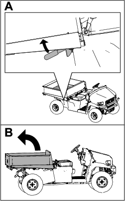
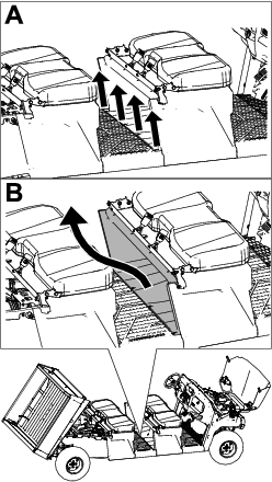
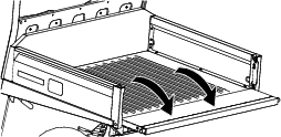
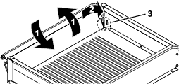
If you unloaded loose material such as sand, landscaping rock, or wood chips from the cargo bed of the machine, some of the material that you unloaded may have lodged in the hinge area of the tailgate. Perform the following steps before closing the tailgate.
-
Use your hands to remove as much of the material from the hinge area as possible.
-
Rotate the tailgate to approximately the 45° position (Figure 70).
-
Use a short, shaking motion to rotate the tailgate back and forth several times (Figure 70).
Note: This action helps move material away from the hinge area.
-
Lower the tailgate and check for material remaining in the hinge area.
-
Repeat steps 1 through 4 until the material is removed from the hinge area.
-
Rotate the tailgate up and lift the tailgate into the notches in the cargo bed.
Starting the Engine
Important: Do not attempt to push or tow the machine to get it started. Damage to the drive train could result.
-
Sit on the operator seat and ensure that the machine is in the P (PARK) position.
-
Rotate the key switch to the ON position.
Note: When the glow-plug-indicator light turns off (approximately 5 to 10 seconds), the engine is ready to start.
-
With your foot off the accelerator pedal, push the brake pedal.
-
Rotate the key switch to the START position.
If your foot is not on the brake pedal, you cannot start the engine.
Note: Release the key immediately when the engine starts and allow it to return to the RUN position.
Note: Do not run the starter motor for more than 10 seconds at a time or premature starter failure may result. If engine fails to start after 10 seconds, turn the key to the OFF position. Check the controls and starting procedure, wait 10 additional seconds, and repeat the starting operation.
Driving the Machine
-
Press the brake pedal.
-
Move the gear selector to the desired gear.
-
Release the brake pedal and gradually press the accelerator pedal.
Important: Always stop the machine before shifting gears.
Use the chart below to determine the ground speed of each gear when operating the machine.
Gear Maximum speed (km/h) Maximum speed (mph) (REVERSE) 0 to 24 0 to 15 (HIGH FORWARD) 0 to 40 0 to 25 (LOW FORWARD) 0 to 24 0 to 15 Note: Leaving the key switch in the ON position for long periods of time without starting the engine discharges the battery.
Using the Cruise Control
In order to use cruise control, your seat belt must be fastened, and you need to be driving at the following ground speed based on your selected gear:
-
H (High Forward) gear—6 km/h (4 mph) or greater
-
L (Low Forward) gear—3 km/h (2 mph) or greater
-
Move the cruise control switch to the ON position (Figure 71).
-
When you reach the desired drive speed, press the cruise control switch up to engage/set the cruise control (Figure 71).
To increase the cruise control speed, press the switch up until you reach the desired speed (Figure 71).
Note: Press the button 1 time to increase the ground speed by an increment of 1 km/h (1 mph).
To disengage cruise control, press the switch to the down, OFF position (Figure 71).
Note: When you press the brake pedal, the cruise control disengages.
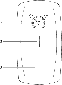
Adjusting the Ground Speed Governor
-
Press and hold the button (Figure 72) for at least 10 seconds.
The set speed will blink.
-
Press the button 1 time to increase the ground speed by an increment of 1 km/h (1 mph).
Note: The maximum ground speed that you can increase to is 40 km/h (25 mph); the minimum is 8 km/h (5 mph).
Stopping the Machine
To stop the machine, remove your foot from the accelerator pedal, then press the brake pedal.
Shutting Off the Engine
-
Stop the machine.
-
Shift the transmission lever to the P (PARK) position.
-
Rotate the key switch to the OFF position and remove the key.
Using the 4-Wheel Drive/Differential Lock(s)
Warning
Loss of control or damage to the machine or turf can happen if you do not properly use the 4-wheel drive/differential lock(s).
-
The machine speed must be at 16 km/h (10 mph) or less to engage the 4-wheel drive.
-
The machine speed must be at 8 km/h (5 mph) or less to engage the differential lock(s).
-
You can release the 4-wheel drive/differential lock(s) while the machine is in motion. The 4-wheel drive/differential lock(s) may stay engaged while an axle load is present. The 4-wheel drive/differential lock(s) releases once you remove an axle load.
-
Use 4-wheel drive/differential lock(s) only when necessary for improved ground engagement.
Warning
Tipping or rolling the machine on a hill will cause serious injury.
-
The extra traction available with the 4-wheel drive/differential lock(s) can be enough to get you into dangerous situations, such as climbing slopes that are too steep to turn around. Be careful when operating with the 4-wheel drive/differential lock(s) on, especially on steeper slopes.
-
If the 4-wheel drive/differential lock(s) are on when making a sharp turn at a higher speed and the inside rear wheel lifts off the ground, there may be a loss of control, which could cause the machine to skid. Use the 4-wheel drive/differential lock(s) only at slower speeds.
Engaging 4-Wheel Drive
-
Ensure that the machine speed is 16 km/h (10 mph) or less and your foot is off the accelerator pedal.
-
Press the 2-wheel drive/4-wheel drive switch (Figure 73) up to engage 4-wheel drive.
Note: You can disengage 4-wheel drive at any speed.
Disengaging 4-Wheel Drive
With your foot off the accelerator pedal, disengage 4-wheel drive by pressing the 2-wheel drive/4-wheel drive switch to the down position (Figure 73).
Note: The 4-wheel drive icon will not be illuminated on the display when the switch is disengaged.
Note: You can release 4-wheel drive while the machine is in motion. 4-wheel drive may stay engaged while an axle load is present. 4-wheel drive releases once you remove an axle load.
Engaging the Differential Lock(s)
-
Ensure that the machine speed is 8 km/h (5 mph) or less and your foot is off the accelerator pedal.
-
Press the differential-lock switch to the mid position to engage the rear differential lock (Figure 73).
Press the differential-lock switch to the up position to engage the front and rear differential locks (Figure 73).
Note: The differential lock(s) are only active when the differential-lock switch is pushed.
Note: The differential-lock(s) icon appears on the display when you engage the differential lock.
Disengaging the Differential Lock(s)
With your foot off the accelerator pedal, disengage the differential lock(s) by pressing the differential-lock switch to the down position (Figure 73).
Note: The differential-lock(s) icon will not be illuminated on the display when the switch is disengaged.
Note: You can release the differential lock(s) while the machine is in motion. The differential lock(s) may stay engaged while an axle load is present. The differential lock(s) release once you remove an axle load.
Controlling the Engine Throttle While in the
If you are warming up the engine in cold weather or if you need to charge your battery using the engine, do the following:
-
Shift the transmission lever to the P (PARK) position.
-
With one foot on the brake pedal, simultaneously press your other foot on the accelerator pedal.
Note: There is no throttle control while in the N (NEUTRAL) position.
Loading the Cargo Bed
Use the following guidelines when loading the cargo bed and operating the machine:
-
Observe the weight capacity of the machine and limit the weight of the load that you carry in the cargo bed as described in Specifications and on the gross vehicle weight tag of the machine.
Note: The load rating is specified for machine operation on a level surface only.
-
Reduce the weight of the load that you carry in the cargo bed when operating the machine on hills and rough terrain.
-
Reduce the weight of the load that you carry when the materials are tall (and have a high center of gravity), such as a stack of bricks, landscaping timbers, or fertilizer bags. Distribute the load as low as possible to ensure that the load does not reduce your ability to see behind the machine when operating it.
-
Keep loads centered by loading the cargo bed as follows:
-
Evenly position the weight in the cargo bed from side to side.
Important: Tipping over is more likely to occur if the cargo bed is loaded to 1 side.
-
Evenly position the weight in the cargo bed from front to back.
Important: Loss of steering control or the machine may tip over if you position the load behind the rear axle and the traction on the front tires is reduced.
-
-
Use extra caution when transporting oversized loads in the cargo bed, particularly when you cannot center the weight of the oversize load to the cargo bed.
-
Whenever possible, secure the load by binding it to the cargo bed so that it does not shift.
-
When transporting liquids, use caution when driving the machine uphill or downhill, when suddenly changing speed or stopping, or when driving over rough surfaces.
The capacity of the cargo bed is 0.45 m3 (15.9 ft3). The amount (volume) of material that you can place in the bed without exceeding the load ratings of the machine can vary greatly depending on the density of the material.
Refer to the following table for load volume limits with various materials:
| Material | Density | Maximum Cargo Box Capacity(on level ground) |
| Gravel, dry | 1522 kg/m3 (95 lb/ft3) | Full |
| Gravel, wet | 1922 kg/m3 (120 lb/ft3) | 3/4 Full |
| Sand, dry | 1442 kg/m3 (90 lb/ft3) | Full |
| Sand, wet | 1922 kg/m3 (120 lb/ft3) | 3/4 Full |
| Wood | 721 kg/m3 (45 lb/ft3) | Full |
| Bark | <721 kg/m3 (<45 lb/ft3) | Full |
| Earth, packed | 1602 kg/m3 (100 lb/ft3) | 3/4 Full (approximately) |
After Operation
After Operation Safety
General Safety
-
Before you leave the operating position, do the following:
-
Park the machine on a level surface.
-
Shift the transmission lever to the P (PARK) position.
-
Shut off the machine and remove the key.
-
Wait for all movement to stop.
-
-
Allow the machine to cool before adjusting, servicing, cleaning, or storing it.
-
Do not store the machine where there is an open flame, spark, or pilot light, such as on a water heater or other appliance.
-
Keep all parts of the machine in good working condition and all hardware tightened.
-
Maintain and clean the seat belt(s) as necessary.
-
Replace all worn, damaged, or missing decals.
Hauling the Machine
-
Use care when loading or unloading the machine into a trailer or a truck.
-
Use full-width ramps for loading the machine into a trailer or a truck.
-
Tie the machine down securely.
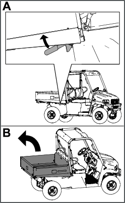
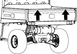
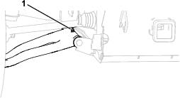
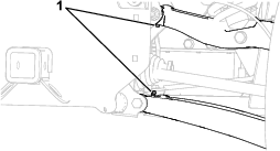
Refer to Figure 74 and Figure 75 for the tie-down locations on the machine.
Note: Load the machine on the trailer with the front of the machine facing forward.
Towing the Machine
In case of an emergency, you can tow the machine for a short distance; however, this is not the standard operating procedure.
Warning
Towing at excessive speeds could cause a loss of steering control, resulting in personal injury.
Never tow the machine at faster than 8 km/h (5 mph).
Note: The power steering may not function, making it difficult to steer.
Towing the machine is a 2-person job. If you must move the machine a considerable distance, transport it on a truck or trailer.
-
Affix a tow line to the tongue at the front of the frame of the machine (Figure 74).
-
Move the gear selector to the N (NEUTRAL) position.
Towing a Trailer
The machine is capable of pulling trailers and attachments. Contact your authorized Toro distributor for the available tow hitches.
Your machine can tow trailers with a maximum gross trailer weight (GTW) up to 907 kg (2,000 lb).
Always load a trailer with approximately 60% of the trailer cargo weight toward the front of the trailer axle. Do not exceed 91 kg (200 lb) of tongue weight on the tow hitch of the machine.
When hauling cargo or towing a trailer, do not overload the machine or trailer. Overloading can cause poor performance or damage to the brakes, axle, engine, transaxle, steering, suspension, body structure, or tires.
Important: To reduce the potential for drive belt damage, use the L (LOW RANGE) position when towing.
Maintenance
Maintenance Safety
-
Do not allow untrained personnel to service the machine.
-
Before you leave the operating position, do the following:
-
Park the machine on a level surface.
-
Shift the transmission lever to the P (PARK) position.
-
Shut off the machine and remove the key.
-
Wait for all movement to stop.
-
-
Allow the machine to cool before adjusting, servicing, cleaning, or storing it.
-
Support the machine with jack stands whenever you work under the machine.
-
Do not work under a raised bed without the proper bed safety support in place.
-
To ensure that the entire machine is in good condition, keep all hardware properly tightened.
-
To reduce the potential fire hazard, keep the machine area free of excessive grease, grass, leaves, and accumulation of dirt.
-
If possible, do not perform maintenance while the machine is running. Keep away from moving parts.
-
If you must run the machine to perform a maintenance adjustment, keep your hands, feet, clothing, and any parts of the body away from any moving parts. Keep bystanders away from the machine.
-
Clean up oil and fuel spills.
-
Keep all parts of the machine in good working condition and all the hardware properly tightened. Replace all worn or damaged decals.
-
Never interfere with the intended function of a safety device or reduce the protection provided by a safety device.
-
Do not overspeed the engine by changing the governor settings. To ensure safety and accuracy, have an authorized Toro distributor check the maximum engine speed with a tachometer.
-
If major repairs are ever necessary or assistance is required, contact an authorized Toro distributor.
-
Altering this machine in any manner may affect the operation of the machine, performance, durability, or its use may result in injury or death. Such use could void the product warranty of The Toro® Company.
Recommended Maintenance Schedule(s)
| Maintenance Service Interval | Maintenance Procedure |
|---|---|
| After the first 50 hours |
|
| Before each use or daily |
|
| Every 100 hours |
|
| Every 250 hours |
|
| Every 500 hours |
|
| Every 1,000 hours |
|
Note: Download a free copy of the electrical schematic by visiting www.Toro.com and searching for your machine from the Manuals link on the home page.
Important: Refer to your engine owner’s manual for additional maintenance procedures.
Warning
Failing to properly maintain the machine could result in premature failure of machine systems, causing possible harm to you or bystanders.
Keep the machine well maintained and in good working order as indicated in these instructions.
Caution
Only qualified and authorized personnel should maintain, repair, adjust, or inspect the machine.
-
Avoid fire hazards and have fire-protection equipment present in the work area. Do not use an open flame to check fluid levels or leakage of fuel, battery electrolyte, or coolant.
-
Do not use open pans of fuel or flammable cleaning fluids for cleaning parts.
Caution
If you leave the key in the switch, someone could accidently start the engine and seriously injure you or other bystanders.
Shut off the engine and remove the key from the switch before you perform any maintenance.
Maintaining the Machine under Special Operating Conditions
Important: If the machine is subjected to any of the conditions listed below, perform maintenance twice as frequently:
-
Desert operation
-
Cold climate operation—below 10°C (50°F)
-
Trailer towing
-
Frequent operation in dusty conditions
-
Construction work
-
After extended operation in mud, sand, water, or similar dirty conditions, do the following:
-
Have your brakes inspected and cleaned as soon as possible. This prevents any abrasive material from causing excessive wear.
-
Wash the machine using water alone or with a mild detergent.
Important: Do not use brackish or reclaimed water to clean the machine.
-
Pre-Maintenance Procedures
Preparing the Machine for Maintenance
-
Park the machine on a level surface.
-
Shift the transmission lever to the P (PARK) position.
-
Raise and empty the cargo bed.
-
Shut off the engine and remove the key.
-
Allow the machine to cool before performing maintenance.
-
Disconnect the negative (-) battery cable from the battery post.
Raising the Machine
Danger
A machine on a jack may be unstable and slip off the jack, injuring anyone beneath it.
-
Do not start the machine while the machine is on a jack, as the engine vibration or wheel movement could cause the machine to slip off the jack.
-
Always remove the key from the key switch before getting off the machine.
-
Block the tires when the machine is on a jack.
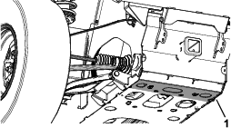
When jacking up the front of the machine, always place a wooden block (or similar material) between the jack and the machine frame.
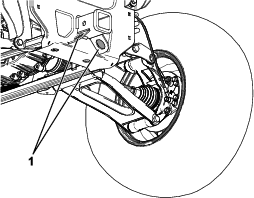
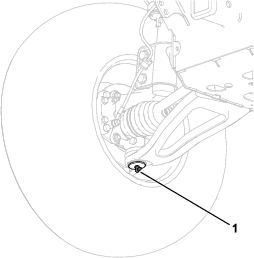
The jacking point at the front of the machine is located at the front frame bottom plate (Figure 76).
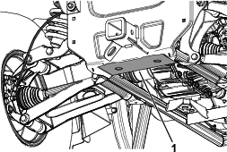
The jacking point at the rear of the machine is located at the rear cradle bracket (Figure 77).
Accessing the Hood
Raising the Hood
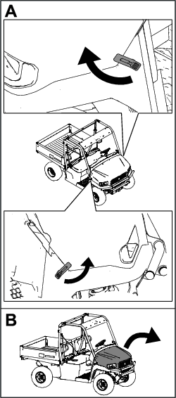
-
Lift up the handle of the rubber latches on each side of the hood.
-
Raise the hood.
Closing the Hood
-
Gently lower the hood.
-
Secure the hood by aligning the rubber latches onto the latch anchors on each side of the hood (Figure 78).
Lubrication
Greasing the Machine
| Maintenance Service Interval | Maintenance Procedure |
|---|---|
| Every 250 hours |
|
Grease Type: No. 2 lithium grease
-
Use a rag to wipe the grease fitting clean so that foreign matter cannot be forced into the bearing or bushing.
-
With a grease gun, apply grease into the grease fittings on the machine.
-
Wipe any excess grease off the machine.
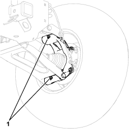
The grease fitting locations and quantities are as follows:
Engine Maintenance
Engine Safety
-
Shut off the engine, remove the key, and wait for all moving parts to stop before checking the oil or adding oil to the crankcase.
-
Keep your hands, feet, face, clothing, and other body parts away from the muffler and other hot surfaces.
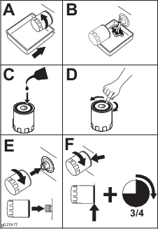
Servicing the Air Cleaner
| Maintenance Service Interval | Maintenance Procedure |
|---|---|
| Every 250 hours |
|
Inspect the air cleaner and hoses periodically to maintain maximum engine protection and to ensure maximum service life. Check the air-cleaner body for damage that could possibly cause an air leak. Replace a damaged air-cleaner body.
-
Release the latches on the air cleaner and pull the air-cleaner cover off the air-cleaner body (Figure 84).
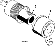
-
Squeeze the dust cap sides to open it and knock the dust out.
-
Gently slide the filter out of the air-cleaner body (Figure 84).
Note: Avoid knocking the filter into the side of the body.
Note: Do not attempt to clean the filter.
-
Inspect the new filter for damage by looking into the filter while shining a bright light on the outside of the filter.
Note: Holes in the filter appear as bright spots. Inspect the element for tears, an oily film, or damage to the rubber seal. If the filter is damaged, do not use it.
Note: To prevent engine damage, always operate the engine with the air filter and cover installed.
-
Carefully slide the filter over the body tube (Figure 84).
Note: Ensure that it is fully seated by pushing on the outer rim of the filter while installing it.
-
Install the air-cleaner cover with the side facing up, and secure the latches (Figure 84).
Servicing the Engine Oil
| Maintenance Service Interval | Maintenance Procedure |
|---|---|
| Before each use or daily |
|
| Every 250 hours |
|
Note: Change the oil more frequently when operating conditions are extremely dusty or sandy.
Note: Dispose of the used engine oil and oil filter at a certified recycling center.
Engine-Oil Specifications
The engine ships with oil in the crankcase; however, check the oil level before you first start the engine. Check the oil level before operating the machine each day or each time you use the machine.
Oil Type: Toro Premium Engine Oil
If using an alternate oil, use high-quality, low-ash engine oil that meets or exceeds the following specifications:
-
API service category CJ-4 or higher
-
ACEA service category E6
-
JASO service category DH-2
Important: Using engine oil other than API classification CJ-4 or higher, ACEA E6, or JASO DH-2 may cause the diesel particulate filter to plug or cause engine damage.
Crankcase Capacity: 2.3 L (2.4 US qt) when the filter is changed
Oil Viscosity/Grade: SAE 10W-30 (all temperatures)
Note: Toro Premium Engine oil is available from your distributor. See the Parts Catalog or contact an authorized Toro distributor for part numbers.
Checking the Engine-Oil Level
-
Park the machine on a level surface.
-
Shift the transmission lever to the P (PARK) position.
-
Shut off the engine and remove the key.
-
Raise the cargo bed.
-
Check the engine-oil level as shown in Figure 85.
Changing the Engine Oil and Filter
If possible, run the engine just before changing the oil because warm oil flows better and carries more contaminants than cold oil.
-
Park the machine on a level surface.
-
Shift the transmission lever to the P (PARK) position.
-
Shut off the engine and remove the key.
-
Raise the cargo bed.
-
Change the engine oil as shown in Figure 86.
-
Replace the engine-oil filter as shown in Figure 87.
-
Fill the crankcase with oil; refer to Engine-Oil Specifications.
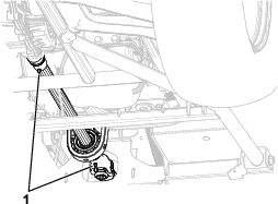
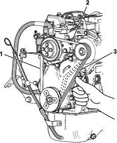
Checking and Adjusting the Alternator Belt
| Maintenance Service Interval | Maintenance Procedure |
|---|---|
| After the first 50 hours |
|
| Every 250 hours |
|
-
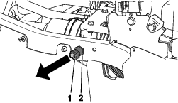
Press the belt inward using your finger or a ruler with a force of approximately 98 N (22 lbf) to check the deflection.
There are 3 positions to check the belt tension (Figure 88). The correct deflection at each position is as follows:
-
Position 1—9 to 13 mm (5/16 to 1/2 inch)
-
Position 2—7 to 10 mm (1/4 to 3/8 inch)
-
Position 3—10 to 14 mm (3/8 to 1/2 inch)
-
-
If needed, adjust the belt tension as follows:
-
Loosen the adjusting bolts and nuts, then move the alternation using a wrench to tighten the belt to the correct tension (Figure 89).
-
Tighten the adjusting bolts and nuts (Figure 89).
-
Tighten the belt to the correct tension.
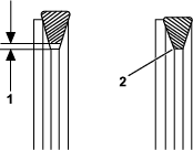
Ensure that there is clearance between the belt and the bottom of the pulley groove. If there is no clearance between the belt and the bottom of the pulley groove, replace the belt (Figure 90).
-
Check the belt for cracks, oil, and/or wear. Replace, if necessary.
Calibrating the Throttle Actuator
| Maintenance Service Interval | Maintenance Procedure |
|---|---|
| Every 500 hours |
|
-
Park the machine on a level surface.
-
Shift the transmission lever to the P (PARK) position.
-
With the engine running and your foot off the brake pedal, press and hold the display button for 10 seconds (Figure 91).
The km/h or mph on the display will start blinking.
-
While pressing and holding the display button, turn the key switch from the RUN position to the START position, then simultaneously let go of both.
The throttle actuator angle will start to increase (1 degree every 2 seconds). When the calibration process is complete, a new offset is created, and the angle on the display shows zero again.
The calibration process takes approximately 30 to 60 seconds to complete.
Note: Do not touch anything during the calibration process, as this will cancel the process, requiring you to restart the procedure.
Note: During calibration, the engine speed (rpm) should remain constant. Only at the end of the calibration process you may hear the engine speed slightly increase. If the engine speed increases continuously, there may be an issue, and the engine speed is not communicating with the TEC controller.
Fuel System Maintenance
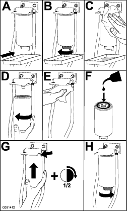
Changing the Fuel Filter/Water Separator
| Maintenance Service Interval | Maintenance Procedure |
|---|---|
| Every 500 hours |
|
Checking the Fuel Lines and Connections
| Maintenance Service Interval | Maintenance Procedure |
|---|---|
| Every 500 hours |
|
Check the fuel lines, fittings, and clamps for signs of leaking, deterioration, damage, or loose connections.
Note: Repair any damaged or leaking fuel system component before using the machine.
Electrical System Maintenance
Electrical System Safety
-
Disconnect the battery before repairing the machine. Disconnect the negative terminal first and the positive last. Connect the positive terminal first and the negative last.
-
Charge the battery in an open, well-ventilated area, away from sparks and flames. Unplug the charger before connecting or disconnecting the battery. Wear protective clothing and use insulated tools.
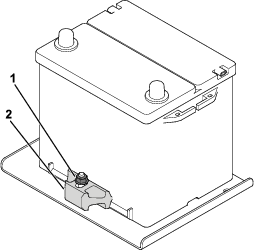
Servicing the Battery
Battery voltage: 12 V with 300 A (cold-cranking) at -18°C (0°F).
-
Always keep the battery clean and fully charged.
-
If the battery terminals are corroded, clean them with a solution of 4 parts water and 1 part baking soda.
-
Apply a light coating of grease to the battery terminals to prevent corrosion.
Danger
Battery electrolyte contains sulfuric acid, which is fatal when consumed and causes severe burns.
-
Do not drink electrolyte and avoid contact with skin, eyes, or clothing. Wear eye protection and rubber gloves.
-
Fill the battery wherever clean water is available for flushing the skin.
-
Charge the battery in a well-ventilated place so that the gasses produced while charging can dissipate.
-
Since the gasses are explosive, keep open flames and electrical sparks away from the battery; do not smoke near the battery.
-
Nausea may result if you inhale the gasses.
-
Unplug the charger from the electrical outlet before connecting the charger leads to or disconnecting them from the battery posts.
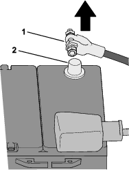
Disconnecting the Battery
Warning
Battery terminals or metal tools could short against metal machine components, causing sparks. Sparks can cause the battery gasses to explode, resulting in personal injury.
-
When removing or installing the battery, do not allow the battery terminals to touch any metal parts of the machine.
-
Do not allow metal tools to short between the battery terminals and metal parts of the machine.
Disconnect the negative (-) battery cable from the battery post (Figure 93).
Removing the Battery
Warning
Incorrect battery cable routing could damage the machine and cables, causing sparks. Sparks can cause the battery gases to explode, resulting in personal injury.
-
Always disconnect the negative (black) battery cable before disconnecting the positive (red) cable.
-
Always connect the positive (red) battery cable before connecting the negative (black) cable.
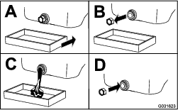
Installing the Battery
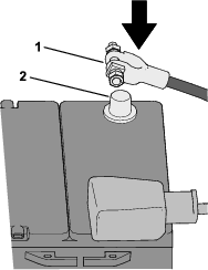
Connecting the Battery
Connect the negative (-) battery cable to the battery post (Figure 96).
Charging the Battery
Warning
Charging the battery produces gasses that can explode.
-
Keep sparks and flames away from the battery.
-
Never smoke near the battery.
Important: Always keep the battery fully charged. This is especially important to prevent battery damage when the temperature is below 0°C (32°F).
-
Remove the battery from the machine; refer to Removing the Battery.
-
Connect a 3 to 4 A battery charger to the battery posts. Charge the battery at a rate of 3 to 4 A for 4 to 8 hours (12 V).
Note: Do not overcharge the battery.
-
Install the battery; refer to Installing the Battery.
Storing the Battery
If you store the machine for more than 30 days, remove the battery and charge it fully. Either store it on the shelf or on the machine. Leave the cables disconnected if it is stored on the machine. Store the battery in a cool atmosphere to avoid quick deterioration of the charge in the battery. To prevent the battery from freezing, make sure it is fully charged.
Drive System Maintenance
Maintaining the Tires
| Maintenance Service Interval | Maintenance Procedure |
|---|---|
| After the first 50 hours |
|
| Every 100 hours |
|
| Every 250 hours |
|
-
Inspect the tires and rims for signs of wear and damage.
Note: Operating accidents, such as hitting curbs, can damage a tire or rim and also disrupt wheel alignment, so inspect tire condition after an accident.
-
Torque the wheel lug nuts to 108 to 122 N∙m (80 to 90 ft-lb).
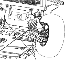
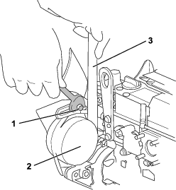
Checking the Steering and Suspension Components
| Maintenance Service Interval | Maintenance Procedure |
|---|---|
| Every 100 hours |
|
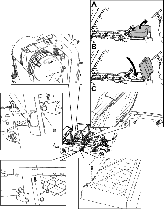
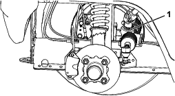
With the steering wheel at the centered position (Figure 99), turn the steering wheel to the left or right. If you turn the steering wheel more than 13 mm (1/2 inch) to the left or right, and the tires do not turn, check the following steering and suspension components to ensure that they are not loose or damaged:
-
Steering shaft to the steering-rack assembly joint
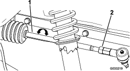
Important: Check the condition and security of the pinion-shaft seal (Figure 100).
-
Steering-rack assembly tie rods
Checking/Adjusting the Front Wheel Alignment
| Maintenance Service Interval | Maintenance Procedure |
|---|---|
| Every 100 hours |
|
Checking the Front Wheel Alignment
-
Check the tire pressure to ensure that the front tires are inflated properly; refer to Checking the Tire Pressure.
-
Either add weight to the driver's seat equal to the average operator who will run the machine, or have an operator sit on the seat. The weight or operator must remain on the seat for the duration of the adjustment procedure.
-
On a level surface, roll the machine straight back 2 to 3 m (6 to 10 ft) and then straight forward to the original starting position. This allows the suspension to settle into the operating position.
-
Ensure that the front tires are facing straight ahead.
-
Measure the distance between both of the front tires at the axle height at both the front and rear of the front tires (Figure 101).

-
If the measurement is not within +/– 6 mm (+/– 1/4 inch) from neutral (zero), proceed to Adjusting the Front Wheel Alignment.
Adjusting the Front Wheel Alignment
Important: Before adjusting the alignment, ensure that the height of the machine is as close to neutral as possible; refer to Adjusting the Front Ride Height.
-
Loosen the jam nuts at the outer end of the tie rods (Figure 102).
-
Rotate both tie rods to move the front of the tire inward or outward.
-
Tighten the tie rod jam nuts when the adjustment is correct.
-
Ensure that there is full travel of the steering wheel in both directions.
-
Check the measurement; refer to Checking the Front Wheel Alignment.
If the measurement is not within +/– 6 mm (+/– 1/4 inch) from neutral (zero), repeat the steps for adjusting the front wheel alignment.
Adjusting the Front Ride Height
Owner-provided tools: spring-adjuster wrench, Toro Part 139-4678; refer to your authorized Toro distributor.
Important: Make height adjustments only if there is uneven tire wear or if you are adding additional weight to the front of the machine (e.g., adding a BOSS plow).
-
If you are adding weight to the front of the machine, adjust the ride height.
Check the tire pressure to ensure that the front tires are inflated properly; refer to Checking the Tire Pressure.
The ground clearance should be 23 cm (9 inches) for standard wheels and tires or 25 cm (10 inches) for the larger accessory wheels and tires.
-
If the ground clearance is not correct, use the spring-adjuster wrench to rotate the collar on the shock absorber to align the wheel (Figure 103).
Note: If the collar is difficult to rotate, raise the front of the machine; Raising the Machine.
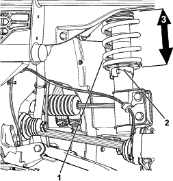
Checking the Transaxle-Fluid Level
| Maintenance Service Interval | Maintenance Procedure |
|---|---|
| Every 250 hours |
|
Fluid Type: Toro Premium Synthetic Transaxle Fluid (Toro Part 145-2048)
-
Park the machine on a level surface.
-
Shift the transmission lever to the P (PARK) position.
-
Shut off the engine and remove the key.
-
Remove the fill plug on the transaxle (Figure 104).
Note: The fluid level should be even with the bottom of the fill plug.
-
If the fluid level is low, remove the fill plug and add the specified fluid until it runs out of the hole (Figure 104).
-
Replace the fill plug and torque it to 14 to 30 N∙m (10 to 22 ft-lb).
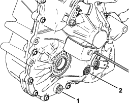
Changing the Transaxle Fluid
| Maintenance Service Interval | Maintenance Procedure |
|---|---|
| Every 500 hours |
|
Fluid Type: Toro Premium Synthetic Transaxle Fluid (Toro Part 145-2048)
Fluid Capacity: 1.21 L (41 fl oz)
-
Align a drain pan under the drain plug (Figure 104).
-
Remove the fill plug (Figure 104).
Note: Retain the fill plug and seal for installation in step 6.
-
Remove the drain plug, and allow the fluid to drain completely (Figure 104).
Note: Retain the drain plug for installation in step 4.
-
Install the drain plug and torque it to 14 to 30 N∙m (10 to 22 ft-lb).
-
Fill the transaxle with the specified fluid and capacity until it is even with the fill hole.
-
Install the fill plug and torque it to 14 to 30 N∙m (10 to 22 ft-lb).
Checking the Front Differential Oil Level
| Maintenance Service Interval | Maintenance Procedure |
|---|---|
| Every 500 hours |
|
Fluid Type: 80W-90 Gear Oil
-
Park the machine on a level surface.
-
Shift the transmission lever to the P (PARK) position.
-
Shut off the engine and remove the key.
-
Remove the check plug on the front differential (Figure 105).
Note: The oil level should be even with the bottom of the check plug.
-
If the oil level is low, you may add the specified oil through the check plug opening (Figure 105).
-
Replace the check plug and torque it to 15 to 25 N∙m (11 to 18 ft-lb).
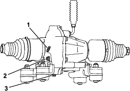
Changing the Front Differential Oil
| Maintenance Service Interval | Maintenance Procedure |
|---|---|
| Every 1,000 hours |
|
Fluid Type: 80W-90 Gear Oil
Fluid Capacity: 0.15 L (5 fl oz)
-
Park the machine on a level surface.
-
Shift the transmission lever to the P (PARK) position.
-
Shut off the engine and remove the key.
-
Align a drain pan under the drain plug (Figure 105).
-
Remove the fill plug (Figure 105).
Note: Retain the fill plug and seal for installation in step 9.
-
Remove the drain plug and allow the fluid to drain completely (Figure 105).
Note: Retain the drain plug for installation in step 7.
-
Install the drain plug and torque it to 15 to 25 N∙m (11 to 18 ft-lb).
-
Fill the front differential with the specified fluid and capacity.
-
Install the fill plug and torque it to 15 to 25 N∙m (11 to 18 ft-lb).
-
Allow the oil to settle for approximately 5 minutes, then check the level; Checking the Front Differential Oil Level.
Cooling System Maintenance
Cooling System Safety
-
Swallowing engine coolant can cause poisoning; keep out of reach from children and pets.
-
Discharge of hot, pressurized coolant or touching a hot radiator and surrounding parts can cause severe burns.
-
Always allow the engine to cool at least 15 minutes before removing the radiator cap.
-
Use a rag when opening the radiator cap, and open the cap slowly to allow steam to escape.
-
-
Do not operate the machine without the covers in place.
-
Keep your fingers, hands and clothing clear of rotating fan and drive belt.
-
Shut off the engine and remove the key before performing maintenance.
Checking the Engine-Coolant Level
| Maintenance Service Interval | Maintenance Procedure |
|---|---|
| Before each use or daily |
|
Coolant type: 50% ethylene-glycol with organic additive technology (OAT) 50% distiller water
Warning
If the engine has been running, the pressurized, hot coolant can escape and cause burns.
-
Do not open the radiator cap when the engine is running.
-
Use a rag when opening the radiator cap, and open the cap slowly to allow steam to escape.
-
Park the machine on a level surface.
-
Shift the transmission lever to the P (PARK) position.
-
Shut off the engine and remove the key.
-
Check the coolant level in the coolant tank (Figure 106).
Note: The fill level depends on the coolant temperature.
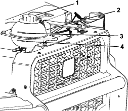
-
If coolant is low, remove the coolant-tank cap and add a 50% ethylene-glycol with organic additive technology (OAT) 50% distiller water antifreeze.
Do not overfill.
-
Hand-tighten the coolant-tank cap.
Removing Debris from the Cooling System
| Maintenance Service Interval | Maintenance Procedure |
|---|---|
| Before each use or daily |
|
-
Park the machine on a level surface.
-
Shift the transmission lever to the P (PARK) position.
-
Shut off the engine and remove the key.
-
Clean the engine area thoroughly of all debris.
-
Remove the 7 screws securing the grill and remove the grill (Figure 107).
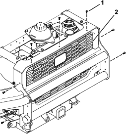
-
Clean the radiator assembly using compressed air.
Note: Blow debris away from the radiator.
-
Install the grill using the previously removed 7 screws (Figure 107).
Checking the Coolant Hoses
| Maintenance Service Interval | Maintenance Procedure |
|---|---|
| Every 500 hours |
|
Check the coolant hoses for cracks, swelling, or deterioration.
Replace the hoses if there are cracks, swelling, or deterioration.
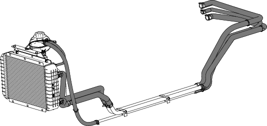
Changing the Engine Coolant
| Maintenance Service Interval | Maintenance Procedure |
|---|---|
| Every 1,000 hours |
|
Contact your authorized Toro distributor.
Brake Maintenance
Checking the Brakes
| Maintenance Service Interval | Maintenance Procedure |
|---|---|
| Every 100 hours |
|
Caution
After operating the machine, the brake components may be hot. Touching hot brake components may burn you.
Before checking the brakes, wait for the brake components to cool down.
Important: Brakes are a critical safety component of the machine. Closely inspect them at the recommended service interval to ensure optimum performance and safety.
-
Check the brake lining for wear or damage. If the lining (brake pad) thickness is less than 1.6 mm (1/16 inch), replace the brake lining.
-
Check the backing plate and other components for signs of excessive wear or deformation. Replace any deformed components.
-
Check the brake-fluid level; refer to Checking the Brake-Fluid Level.
Checking the Brake-Fluid Level
| Maintenance Service Interval | Maintenance Procedure |
|---|---|
| Before each use or daily |
|
Brake-fluid type: DOT 3
-
Park the machine on a level surface.
-
Shift the transmission lever to the P (PARK) position.
-
Shut off the engine and remove the key.
-
Raise the hood to access to the master brake cylinder and reservoir (Figure 109).
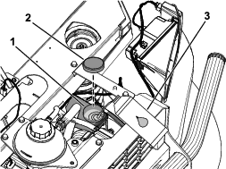
-
Look at the outline of the fluid level at the side of the reservoir (Figure 110).
Note: The level should be above the Minimum line.
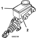
-
If the fluid level is low, preform the following:
-
Close the hood.
Changing the Brake Fluid
| Maintenance Service Interval | Maintenance Procedure |
|---|---|
| Every 1,000 hours |
|
Contact your authorized Toro distributor.
Belt Maintenance
Servicing the Drive Belt
Checking the Drive Belt and Cleaning the Clutches
| Maintenance Service Interval | Maintenance Procedure |
|---|---|
| Every 250 hours |
|
-
Park the machine on a level surface.
-
Shift the transmission lever to the P (PARK) position.
-
Shut off the engine and remove the key.
-
Raise the cargo bed.
-
Unlatch the 6 spring clips securing the belt cover and remove the cover (Figure 111).
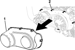
-
Rotate and inspect the belt (Figure 112) for signs of excessive wear or damage.
Note: Replace the belt if it is excessively worn or damaged; refer to Replacing the Drive Belt.
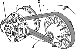
-
Using compressed air, clean the clutches thoroughly of all debris (Figure 112).
-
Install the belt cover (Figure 111).
-
Lower the cargo bed.
Replacing the Drive Belt
| Maintenance Service Interval | Maintenance Procedure |
|---|---|
| Every 500 hours |
|
-
Park the machine on a level surface.
-
Shift the transmission lever to the P (PARK) position.
-
Shut off the engine and remove the key.
-
Raise the cargo bed.
-
Unlatch the 6 spring clips securing the belt cover and remove the cover (Figure 111).
-
Pull up on the top of the belt to spread out the secondary clutch, then rotate and route the belt over the secondary clutch (Figure 112).
-
Remove the belt from the primary clutch (Figure 112).
Note: Discard the old belt.
-
Align the new belt over the primary clutch (Figure 112).
-
Rotate and route the belt over the secondary clutch (Figure 112).
-
Install the belt cover (Figure 111).
-
Lower the cargo bed.
Cleaning
Washing the Machine
Wash the machine as needed using water alone or with a mild detergent. You may use a rag when washing the machine.
Important: Do not use brackish or reclaimed water to clean the machine.
Important: Do not use power-washing equipment to wash the machine. Power-washing equipment may damage the electrical system, loosen important decals, or wash away necessary grease at friction points. Avoid excessive use of water near the control panel, engine, and battery.
Important: Do not wash the machine with the engine running. Washing the machine with the engine running may result in internal engine damage.
Storage
Storage Safety
-
Shut off the engine, remove the key, and wait for all movement to stop before you leave the operator’s position. Allow the machine to cool before adjusting, servicing, cleaning, or storing it.
-
Do not store the machine or fuel container where there is an open flame, spark, or pilot light, such as on a water heater or other appliance.
Storing the Machine
-
Position the machine on a level surface, shift the transmission lever to the P (PARK) position, shut off the engine, and remove the key from the key switch.
-
Clean dirt and grime from the entire machine, including the engine area
Important: You can wash the machine with mild detergent and water. Do not use high-pressure water to wash the machine. Pressure washing the machine may damage the electrical system or wash away necessary grease at friction points. Avoid excessive use of water, especially near the control panel, lights, engine, and battery.
-
Service the air cleaner; refer to Servicing the Air Cleaner.
-
Grease the machine; refer to Greasing the Machine.
-
Change the engine oil and filter; refer to Changing the Engine Oil and Filter.
-
Check the tire pressure; refer to Checking the Tire Pressure.
-
For long-term storage (3 months or more), prepare the fuel system as follows:
-
Add a petroleum based stabilizer/conditioner to the fuel in the tank. Do not use an alcohol-based stabilizer (ethanol or methanol).
Important: Do not store fuel containing stabilizer/conditioner longer than the duration recommended by the fuel stabilizer manufacturer.
-
Run the engine to distribute conditioned fuel through the fuel system for 5 minutes.
-
Shut off the engine, allow it to cool, and drain the fuel tank.
-
Start the engine and run it until it stops.
-
Start and run the engine again until it does not start again.
-
Dispose of drained fuel properly. Recycle as per local codes.
-
-
Check the anti freeze protection and add a 50/50 solution of water and anti freeze as needed for expected minimum temperature in your area.
-
Remove the battery from the chassis, and charge it fully; refer to Removing the Battery.
Note: Do not connect the battery cables to the battery posts during storage.
Important: The battery must be fully charged to prevent it from freezing and being damaged at temperatures below 0°C (32°F). A fully charged battery maintains its charge for about 50 days at temperatures lower than 4°C (40°F). If the temperatures will be above 4°C (40°F), check the water level in the battery and charge it every 30 days.
-
Check and tighten all fasteners. Repair or replace any part that is damaged.
-
Paint all scratched or bare metal surfaces with paint available from your authorized Toro distributor.
-
Store the machine in a clean, dry garage or storage area.
-
Remove the key from the key switch and put it in a safe place that is out of the reach of children.
-
Cover the machine to protect it and keep it clean.
Troubleshooting
| Problem | Possible Cause | Corrective Action |
|---|---|---|
| The engine does not crank over. |
|
|
| The engine cranks, but does not start. |
|
|
| The power steering moves hard. |
|
|
| The throttle is not responding. |
|
|
| The 4-wheel drive/differential locks are not working. |
|
|
| The cruise control feature does not engage. |
|
|
| The clutch engagement is abrupt. |
|
|
| The acceleration seems too slow when the engine is at maximum speed (rpm). |
|
|
| The battery is not charging. |
|
|
| The tachometer on the display is sporadic/inconsistent. |
|
|
| The engine does not reach maximum rpm while driving. |
|
|
| Problem | Possible Cause | Corrective Action |
|---|---|---|
| A fault code appears on the display. |
|
|