Introduction
This machine is an attachment for a TRX trencher intended for use by landscape professionals and rental equipment operators. It is designed for boring holes through soil under drives and sidewalks and for pulling cabling and piping through the bored holes. It is not designed for boring through rock or other non-soil debris. Using this product for purposes other than its intended use could prove dangerous to you and bystanders.
Read this information carefully to learn how to operate and maintain your product properly and to avoid injury and product damage. You are responsible for operating the product properly and safely.
Visit www.Toro.com for more information, including safety tips, training materials, accessory information, help finding a dealer, or to register your product.
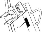
Whenever you need service, genuine Toro parts, or additional information, contact an Authorized Service Dealer or Toro Customer Service and have the model and serial numbers of your product ready. Figure 1 identifies the location of the model and serial numbers on the product. Write the numbers in the space provided.
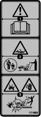
This manual identifies potential hazards and has safety messages identified by the safety-alert symbol (Figure 2), which signals a hazard that may cause serious injury or death if you do not follow the recommended precautions.

This manual uses 2 words to highlight information. Important calls attention to special mechanical information and Note emphasizes general information worthy of special attention.
Warning
CALIFORNIA
Proposition 65 Warning
Use of this product may cause exposure to chemicals known to the State of California to cause cancer, birth defects, or other reproductive harm.
Safety
Danger
There may be buried utility lines in the work area. Digging into them may cause a shock or an explosion.
Have the property or work area marked for buried lines and do not dig in marked areas. Contact your local marking service or utility company to have the property marked (for example, in the US, call 811 or in Australia, call 1100 for the nationwide marking service).
General Safety
This product is capable of amputating hands and feet. Always follow all safety instructions to avoid serious injury or death. Using this product for purposes other than its intended use could prove dangerous to you and bystanders.
-
Have the property or work area marked for buried lines and other objects, and do not dig in marked areas.
-
Keep your hands and feet away from moving teeth, auger, or other parts.
-
Keep bystanders and pets away from the machine.
-
Read and understand the content of this Operator’s Manual before starting the engine.
-
Never allow children or untrained people to operate the machine.
-
Do not operate the machine without the guards and other safety protective devices in place and working on the machine.
-
Use your full attention while operating the machine. Do not engage in any activity that causes distractions; otherwise, injury or property damage may occur.
-
Stop the machine, shut off the engine, and remove the key before servicing, fueling, or unclogging the machine.
Improperly using or maintaining this machine can result in injury. To reduce the potential for injury, comply with these safety instructions and always pay attention to the safety-alert symbol, which means Caution, Warning, or Danger—personal safety instruction. Failure to comply with these instructions may result in personal injury or death.
You can find additional safety information where needed throughout this manual.
Bore Drive Safety
-
Rotating rod and bits can entangle loose clothing, hands, arms, legs, and feet, causing death or serious injury.
-
Keep at least 3 m (10 ft) from rotating parts, unless you are operating the rod guide tool.
-
Use only the rod guide tool to start the rod and boring bit.
-
Keep extremities and other parts of your body or clothing away from rotating parts.
-
Never straddle or stand on the rod when the engine is running.
-
Do not wear loose clothing or jewelry while operating or assisting with the boring unit.
-
Use caution when standing next to trenches and be aware of weak or collapsing trench walls.
-
Always shut off the engine and remove the key before changing accessories.
-
Do not service the attachment unless rod rotation is stopped, the hydraulics lever is in neutral, and the engine is stopped.
-
Do not use bolts or pins in place of push button connectors.
-
-
Hydraulic couplers, hydraulic lines/valves, and hydraulic fluid may be hot and can burn you if you touch them.
-
Wear gloves when operating the hydraulic couplers.
-
Allow the traction unit to cool before touching hydraulic components.
-
Do not touch hydraulic fluid spills.
-
-
Always use 2 people to operate the attachment, 1 to operate the traction unit and the other to guide the boring unit with the guide tool.
-
Lightning can cause severe injury or death. If lightning is seen or thunder is heard in the area, do not operate the machine; seek shelter.
Hydraulic System Safety
-
Seek immediate medical attention if fluid is injected into skin. Injected fluid must be surgically removed within a few hours by a doctor.
-
Ensure that all hydraulic-fluid hoses and lines are in good condition and all hydraulic connections and fittings are tight before applying pressure to the hydraulic system.
-
Keep your body and hands away from pinhole leaks or nozzles that eject high-pressure hydraulic fluid.
-
Use cardboard or paper to find hydraulic leaks.
-
Safely relieve all pressure in the hydraulic system before performing any work on the hydraulic system.
Safety and Instructional Decals
 |
Safety decals and instructions are easily visible to the operator and are located near any area of potential danger. Replace any decal that is damaged or missing. |
Setup
Determine the left and right sides of the machine from the normal operating position.
Preparing the Machine
-
Park the machine on a level surface, engage the parking brake, and lower the boom.
-
Shut off the engine and remove the key.
-
Allow the machine to cool fully.
Disconnecting the Existing Hydraulic Hoses
TRX-16, TRX-20, and TRX-26
Note: This procedure causes some hydraulic fluid leakage. Ensure that you perform it in an area equipped to catch or easily clean spilled hydraulic fluid.
Caution
Hydraulic couplers, hydraulic lines/valves, and hydraulic fluid may be hot. If you contact hot components, you may be burned.
-
Wear gloves when operating the hydraulic couplers.
-
Allow the machine to cool before touching hydraulic components.
-
Do not touch hydraulic fluid spills.
-
Move the hydraulic lever back and forth a few times to relieve any pressure in the lines.
-
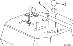
Remove the traction-control handle (Figure 3).
-
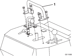
Remove the reference bar (Figure 4)
-
Disconnect the spring from the hydraulics lever and remove it as shown in Figure 5.
-
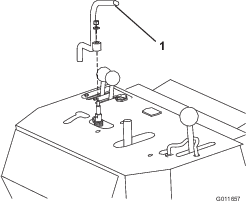
Thread the knob off of the boom-control lever (Figure 6).
-
From under the control panel, remove the hairpin cotter and washer that secure the boom-control lever lock and remove the lock (Figure 6)
-
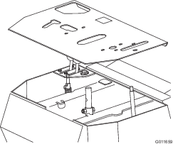
Remove the control panel as shown in Figure 7.
-
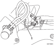
Disconnect the hydraulic hoses shown in Figure 8 from the hydraulics lever valve.
-
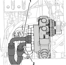
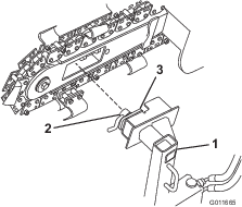
Disconnect the hydraulic hoses from the hydraulic motor on the trencher (Figure 12).
-
Remove and discard the bolt, nut, and hose clamp securing the hoses to the trencher frame.
-
Remove and discard the hydraulic hoses you disconnected from the machine.
TRX-250 and TRX-300
Note: This procedure causes some hydraulic fluid leakage. Ensure that you perform it in an area equipped to catch or easily clean spilled hydraulic fluid.
Caution
Hydraulic couplers, hydraulic lines/valves, and hydraulic fluid may be hot. If you contact hot components, you may be burned.
-
Wear gloves when operating the hydraulic couplers.
-
Allow the machine to cool before touching hydraulic components.
-
Do not touch hydraulic fluid spills.
-
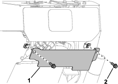
Remove the rear guard (Figure 10).
-
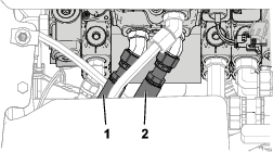
Disconnect the hydraulic hoses shown in Figure 11 from the hydraulics lever valve.
-
Disconnect the hydraulic hoses from the hydraulic motor on the trencher (Figure 12).
-
Remove and discard the bolt, nut, and hose clamp securing the hoses to the trencher frame.
-
Remove and discard the hydraulic hoses you disconnected from the machine.
Installing the Hydraulic Manifold
Parts needed for this procedure:
| Manifold bracket | 1 |
| Carriage bolt (5/16 x 1 inch) | 1 |
| Locknut (5/16 inch) | 3 |
| Hydraulic manifold assembly | 1 |
| Hex socket-head bolt (5/16 x 3-1/4 inches) | 2 |
-
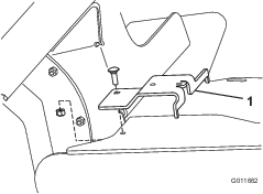
Using a carriage bolt (5/16 x 1 inch) and locknut (5/16 inch), install the manifold bracket to the trencher frame in the hole that you opened when you removed the hose clamp (Figure 13).
-
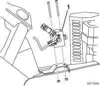
Install the hydraulic manifold to the manifold bracket using 2 hex socket-head bolts (5/16 x 3-1/4 inches) and 2 locknuts (5/16 inch) as shown in Figure 14.
Connecting the Hydraulic Hoses
Parts needed for this procedure:
| Hydraulic hose with short elbow fitting (TRX-16, TRX-20, and TRX-26 only) | 1 |
| Hydraulic hose with long elbow fitting (TRX-16, TRX-20, and TRX-26 only) | 1 |
| Long hydraulic hose with straight fittings | 2 |
| Short hydraulic hose with straight fittings (TRX-250 and TRX-300 only) | 2 |
TRX-16, TRX-20, and TRX-26
-
Route the hydraulic hose with the short elbow fitting on one end from the hydraulic manifold to the hydraulic lever valve, with the elbow fitting near the hydraulic lever valve.
-
Connect the short elbow fitting to the bottom port on the valve (Figure 15).
-
Connect the straight end of the hose to port T (right port) on the back of the hydraulic manifold (Figure 16).
-
Route the hydraulic hose with the long elbow fitting from the hydraulic manifold to the hydraulic lever valve, with the elbow fitting near the hydraulic lever valve.
-
Connect the long elbow fitting to the top port on the valve (Figure 15).
-
Connect the straight end of the hose to port P (left port) on the back of the hydraulic manifold (Figure 16).
-
Connect a long hose with straight fittings to each of the 2 open ports on the front of the hydraulic manifold.
Note: The short hydraulic hoses are 103 cm (40-1/2 inches) long. The long hoses are 105 cm (41-1/2 inches) long.
-
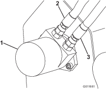
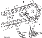
Loop the hoses up and around so that the open fittings are at the open ports on the hydraulic motor on the trencher (Figure 16).
-
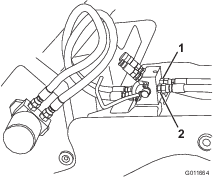
Connect the left hose to the lower port on the motor (Figure 17).
-
Connect the right hose to the upper port on the motor (Figure 17).
-
Ensure that all hoses are tightened securely.
TRX-250 and TRX-300
-
Route the short hydraulic hoses with straight fittings from the hydraulic manifold to the hydraulic lever valve.
Note: The short hydraulic hoses are 103 cm (40-1/2 inches) long. The long hoses are 105 cm (41-1/2 inches) long.
-
Connect the straight fittings to the empty ports on the hydraulic lever valve (Figure 18).
-
Connect the other end of the left hose to port T (right port) on the back of the hydraulic manifold and the other end of the right hose to port P (left port) as shown in Figure 19.
-
Connect the long hoses with straight fittings to the 2 open ports on the front of the hydraulic manifold.
-
Loop the hoses up and around so that the open fittings are at the open ports on the hydraulic motor on the trencher (Figure 19).
-
Connect the left hose to the lower port on the motor (Figure 20).
-
Connect the right hose to the upper port on the motor (Figure 20).
-
Ensure that all hoses are tightened securely.
Checking the Hydraulics
-
For TRX-16, TRX-20, and TRX-26, install the control panel as follows:
-
Place the control panel as shown in Figure 7.
-
Install the boom-control lever lock and secure it with the hairpin cotter and washer you removed previously (Figure 6).
-
Install the knob on the boom-control lever (Figure 6).
-
Install the hydraulics lever as shown in Figure 5, then attach the spring.
-
Install the traction handle and reference bar together (Figure 3 and Figure 4).
Important: Pull the traction handle tight against the reference bar when you tighten it to ensure that the machine tracks straight when finished.
-
-
For TRX-250 and TRX-300, install the rear guard (Figure 10).
-
Start the engine, raise the boom, and operate the trencher chain for a few seconds.
-
Shut off the engine and remove the key.
-
Check all connections for leaks.
-
Check the hydraulic fluid level and add fluid if necessary; refer to the Operator’s Manual for the machine.
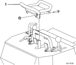
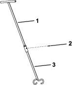
Assemble the Rod Guide
Parts needed for this procedure:
| Rod guide, lower half | 1 |
| Rod guide, upper half | 1 |
| Roll pin | 1 |
-
Slide the upper half of the rod guide into the socket of the lower half, ensuring that the holes align.
-
Secure the connection with a roll pin (Figure 21).
Connecting the Drive Head to the Trencher
Parts needed for this procedure:
| Drive head | 1 |
-
Start the engine and raise the boom to the highest position.
-
Shut of the engine, remove the key, and move the boom-control lock lever to the locked position.
-
Loosen the lever-lock bolt on the drive head and turn the clamp plate so that it is parallel to the drive head (Figure 22).
-
Slide the bore-drive head through the opening in the trencher boom as shown in Figure 22.
-
Rotate the clamp plate 90 degrees and tighten the lever-lock bolt; flip the lever to lock it in place (Figure 23).
-
Move the hydraulics lever back and forth a few times to relieve pressure in the system.
-
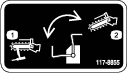
Lower the switching lever on the hydraulic manifold to switch from trencher operation to bore drive head operation (Figure 24).
-
Connect the male and female couplers on the bore drive head hoses to the appropriate couplers on the hydraulic manifold.
To remove the bore drive head, raise the boom to the highest position, shut off the machine, remove the key, move the boom-control lever lock to the locked position, and reverse this procedure.
Product Overview
Specifications and design are subject to change without notice.
| Weight | 30 kg (60 lb) |
| Boring diameter | 3.2 to 8.9 cm |
| (1-1/4 to 3-1/2 inches) |
To ensure optimum performance and continued safety certification of the machine, use only genuine Toro replacement parts and accessories. Replacement parts and accessories made by other manufacturers could be dangerous, and such use could void the product warranty.
Operation
Installing an Accessory
Toro offers several different rods and bits for use with the attachment. Purchase accessories from your Authorized Toro Dealer.
-
Park the machine on a level surface, engage the parking brake, and lower the boom.
-
Shut off the engine and remove the key.
-
Slide the hex shaft of a rod, boring bit, or reamer into the socket. Align the hole in the socket with the push-button connector (Figure 25).
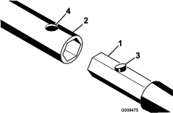
-
Press down the push-button connector and push the shaft into the socket until the connector snaps into the hole in the socket (Figure 25).
-
Repeat steps 3 and 4 as needed to add parts.
Removing an Accessory
-
Park the machine on a level surface, engage the parking brake, and lower the boom.
-
Shut off the engine and remove the key.
-
Press down the push-button connector securing the accessory shaft in the socket and pull the accessory out of the socket.
Boring a Hole
Digging the Trenches
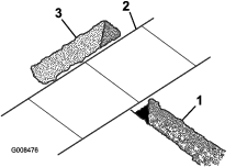
Before drilling under a walk or driveway, make an entrance and an exit trench on either side of the drilling area (Figure 26).
-
Both trenches must be at least 15.2 cm (6 inches) wide and 45.7 cm (18 inches) deep.
-
The entrance trench must be at least 2.1 m (7 ft) long and perpendicular to the walk or driveway.
-
The exit trench must be 0.9 to 1.8 m (3 to 6 ft) long, parallel to the walk or driveway, and centered across the entrance trench.
Boring the Hole
Important: Boring a hole requires 2 people. Do not attempt to perform this operation by yourself.
-
Position the traction unit with the drive head at the beginning of the trench
-
Shut off the engine, remove the key, and wait for all moving parts to stop.
-
Connect a rod and boring bit onto the drive head; refer to Installing an Accessory.
-
Connect the rod guide to the rod just behind the boring bit (Figure 27).
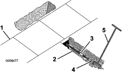
-
Position the person guiding the boring bit to the right of the trench.
-
Start the engine, move the throttle lever midway between the SLOW and FAST positions, and hold the hydraulics lever to the reference bar to start the forward rotation of the boring bit.
-
Slowly move the traction unit forward, while the person with the rod guide tool guides the boring bit into the soil (Figure 27).
-
Once the entire bit is in the soil, release the hydraulics lever.
-
Shut off the engine, remove the key, and wait for all moving parts to stop.
-
Check the grade of the rod.
Note: If the rod is not within the grade tolerances for the job being performed, start the engine, drive backward to pull the boring bit out of the soil, then repeat steps 5 through 10, making adjustments to correct the grade.
-
Remove the rod guide tool.
-
Start the engine and hold the hydraulics lever to the reference bar to start the boring bit.
-
Slowly move the traction unit forward as the boring bit digs into the soil.
Important: Do not drive too fast, forcing the bit into the soil. Allow the bit to progress at its own rate. Never push or pull the bit through the soil when the drive head is not turning.
-
When about 15 cm (6 inches) of the rod is left showing in the entrance trench or when the boring bit completely enters and bores into the far side of the exit trench, stop the traction unit, release the hydraulics lever, shut off the engine, and remove the key.
-
If the boring bit has not yet entered the exit trench, complete the following:
-
Detach the rod from the drive head.
-
Start the engine and back up to the end of the entrance trench.
-
Shut off the engine and wait for all moving parts to stop.
-
Connect another rod and repeats steps 12 through 15.
-
Reaming the Hole
-
With a shovel, carefully dig around the boring bit, clearing it of soil until the bit can be removed (Figure 28).
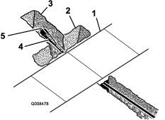
-
Remove the boring bit and attach the reamer (Figure 28); refer to Installing an Accessory.
-
Attach the cable or piping being installed to the swivel on the end of the reamer (Figure 28).
-
Start the engine and hold the hydraulics lever to the reference bar to start the reamer.
-
Slowly move the traction unit rearward as the reamer digs into the soil.
Important: Do not drive too fast, forcing the reamer into the soil. Allow the reamer to progress at its own rate. Never push or pull the reamer through the soil when the drive head is not turning.
-
When a rod coupling is about 15 cm (6 inches) into the entrance trench or when the reamer completely enters the trench with about 15 cm (6 inches) of the cable or piping, stop the traction unit, release the hydraulics lever, shut off the engine, and remove the key.
-
If the reamer has not yet entered the exit trench, complete the following:
-
Detach the rod from the drive head and rod still in the soil.
-
Start the engine and move to the front of the entrance trench.
-
Shut off the engine, remove the key, and wait for all moving parts to stop.
-
Connect the drive head to the rod shaft in the soil.
-
Repeat steps 4 through 7.
-
-
With the reamer and cable/piping in the entrance trench, remove the cable/piping from the reamer.
Storage
-
Before long term storage, wash the attachment with mild detergent and water to remove dirt and grime.
-
Check the condition of the hydraulic hoses. Replace any damaged hoses.
-
Ensure that all hydraulic couplers are connected together to prevent contamination of the hydraulic system.
-
Check and tighten all bolts, nuts, and screws. Repair or replace any damaged or worn part.
-
Paint all scratched or bare metal surfaces. Paint is available from your Authorized Service Dealer.
-
Store the attachment in a clean, dry garage or storage area. Cover it to protect it and keep it clean.