This product complies with all relevant European directives. For details, please see the Declaration of Incorporation (DOI) at the back of this publication.
Safety
Safety and Instructional Decals
 |
Safety decals and instructions are easily visible to the operator and are located near any area of potential danger. Replace any decal that is damaged or missing. |


Installation
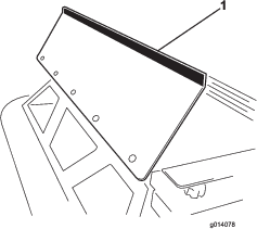
Installing the Hopper Guard
Parts needed for this procedure:
| Hopper guard | 1 |
| Bolt (1/4 x 5/8 inch) | 5 |
| Flange nut (1/4 inch) | 5 |
-
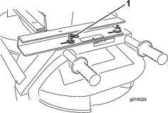
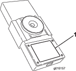
Remove the hopper front guard from its shipping position.
-
Install the hopper guard to the front of the spreader hopper with 5 bolts (1/4 x 5/8 inch) inch bolts and flange nuts (Figure 1).
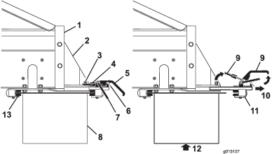
Installing the Twin Spinner
Parts needed for this procedure:
| Twin spinner | 1 |
| Quick attach mounting clamps (supplied with the MH–400) | 2 |
The MH-400 comes equipped with a pair of quick attach mounting clamps. Use these clamps to mount the twin spinner to the MH-400.
-
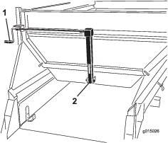
Remove the safety latch clips from the clamp handles (Figure 2).
-
Lift the safety latch, then lift the option attachment clamp handles, and release the lock rings from the lock pins (Figure 2).
-
Slide the rear option attachment clamp assembly out of the quick-attach slots (Figure 2).
-
With assistance, insert the front edge of the twin spinner up and under the rear of the MH-400 into the front clamps on the brackets (Figure 2).
-
While supporting the twin spinner, slide the rear option attachment clamp assembly back into the slots in the brackets, and over the rear edge (Figure 2).
-
Ensure that the twin spinner is centered between the brackets. Then re-install the lock rings over the lock pins and push down on the clamp handles.
Note: If the clamp assembly is too loose and the twin spinner slides within the clamps, turn the lock rings into the clamps a few turns until the twin spinner is secure.
Important: Do not over-tighten the clamps. This may bend the edges of the twin spinner.
-
Reinstall the safety latch clips to the clamp handles (Figure 2).
Important: Ensure that you install the safety latch clips into the clamps. Otherwise, the clamps may open during operation.
Warning
The twin spinner is heavy.
Have an assistant help you lift the twin spinner.
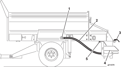
Connecting the Hydraulic Hoses
Warning
If the twin spinner is on when you connect the hydraulic hoses, the twin spinner will spin and could cause injury to you or bystanders.
Turn off the tow vehicle before making the hydraulic connections.
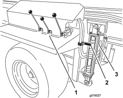
Connect the hydraulic hoses to the option control valve on the MH-400 as follows (Figure 3):
-
Pull back (or push forward) on the outer sleeve of the female connector and insert the male connector.
-
Hold the male connector firmly in place and release the outer sleeve of the female connector.
-
Ensure that the connectors are pushed all the way in and are securely locked in place.
-
With the tow vehicle hydraulics operating, pull back on the option control lever on the SH models or start the option using the option start button on the wireless controller on the EH models, and ensure that the twin spinner is operating properly.
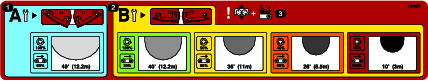
Setting the Desired Spread Pattern
Select the Desired Spread Pattern
-
A-Ultra Light Pattern
-
B-Light to Heavy Spread Pattern
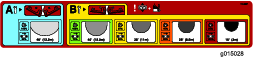
Note: The Twin Spinner is shipped from the factory in the “B” position.
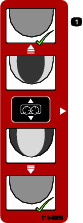
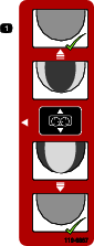
Review the blade position and change the blades, if necessary.
Note: For this example, we will select YELLOW.
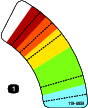
Setting the Drop Zone Position
-
Loosen the handle on each side of the twin spinner (Figure 5).
-
Slide the twin spinner fore and aft until the arrows match the desired color.
-
Tighten the handles.
Note: For this example, we will select YELLOW.
Adjusting the Spinner Valve
MH-400 SH models
-
Loosen the knob securing the spinner valve lever (Figure 6).
-
Rotate the spinner valve lever to the desired color (Figure 6).
Note: For this example, we will select YELLOW
MH-400 EH models
Move the spinner valve lever to the BLUE section (MAX SPEED) (Figure 6). The lever should be horizontal when turned completely clockwise.
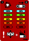
Use the spinner percent listed on the spread pattern decal or the wireless remote decal to determine the value that is inputted into the wireless controller.
Refer to the MH-400 Operator's Manual for the operating instructions.
Note: For this example, we will set the option percent to 50 percent matching the yellow color spread pattern previously selected.
Adjusting the Hopper Gate and Belt Speed
MH-400 SH models
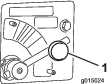
Rotate the crank to adjust the cylinder until the arrow aligns with the center of the YELLOW section, which is number 3 (Figure 7).
The adjustment of the spread density will be controlled through the main hopper gate opening or through the tow vehicle.
MH-400 EH models
Note: For this example, we will select the YELLOW section.
Using the wireless controller, set the floor belt speed to the corresponding color.
Note: For this example, we will set the option percent to 80 percent matching the yellow color spread pattern previously selected.
Refer to the MH-400 Operator's Manual for the operating instructions.
Adjusting the Main Hopper Height
Using the hydraulic controls on the SH model or the wireless controller on the EH model, adjust the main hopper hydraulic cylinders until the arrow aligns with the GREEN section on the hydraulic cylinder decal (Figure 8).
Refer to the MH-400 Operator's Manual for the operating instructions.
Operate the Twin Spinner
Operate the machine to verify that the desired performance is attained. Refer to the MH-400 Operator's Manual for the operating instructions.
Affixing the Decal to the Wireless Controller
Parts needed for this procedure:
| Decal (Part No. 119-6858) | 1 |
Affix the decal to the battery cover on the back of the wireless controller (Figure 9).
Fine-Tuning the Twin Spinner
-
Verify that all the settings are correct.
-
If the spread pattern is not to the desired consistency, loosen the handles and slide the hopper in the desired direction to attain the desired spread pattern.