Safety
Safety and Instructional Decals
 |
Safety decals and instructions are easily visible to the operator and are located near any area of potential danger. Replace any decal that is damaged or missing. |


Installation
Preparing the Machine
-
Park the machine on a level surface.
-
Engage the parking brake.
-
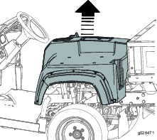
Raise or remove the bed from the machine (if equipped).
Note: Refer to the machine Operator’s Manual for more detailed information on raising and removing the bed.
-
Shut off the engine and remove the key.
-
Disconnect the battery; refer to the Operator’s Manual.
-
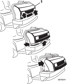
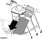
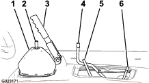
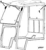
While grasping the hood in the headlight openings, lift up on the hood to release the lower mounting tabs from the slots in the bumper (Figure 1).
-
Pivot the bottom of the hood upward until you can pull the top mounting tabs from the frame slots (Figure 1).
-
Pivot the top of the hood forward and unplug the wire connectors from the headlights (Figure 1).
-
Remove the hood.
Removing the Center Console Panel and Seats
Removing the Center Console Panel
Removing the Center Console Panel
-
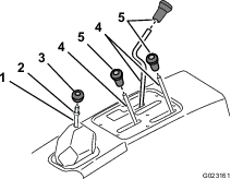
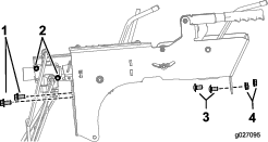
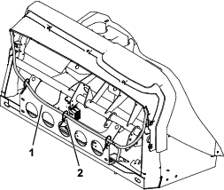
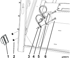
Remove all the knobs from the console levers and from the transmission lever by rotating the knobs counterclockwise (Figure 4).
-
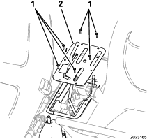
Remove the 4 hex-head screws securing the shift-indicator cover to the seat shroud (Figure 5).
-
Lift the shift indicator up, disconnect the indicator connector from the machine harness connector, and remove the indicator cover from the machine (Figure 5).
-
Remove the 6 hex-head screws securing the control cover to the seat shroud, and remove the control cover (Figure 5).
Removing the Seats
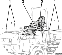
Remove the 8 socket-head bolts securing the seat rails of the seat to the chassis, and remove the seats (Figure 6).
Removing the CVT Cooling Duct (HDX-Auto Machines only), Coolant Tank, ROPS Assembly, and Seat Shroud
Removing the CVT Cooling Duct
Remove the hose clamp securing the CVT-cooling duct to the flange of the CVT intake at the back of the ROPS panel on the passenger side (Figure 7).
Removing the Coolant Tank
-
Lift the coolant tank up and out of the support pocket on the back of the seat shroud (Figure 8).
-
Set the coolant tank upright onto the engine/chassis.
Removing the ROPS Assembly
Removing the Seat Shroud
For Workman HDX machines:
-
Engage the parking brake (Figure 11).
-
Move the differential-lock rod forward and to the right to lock it in the engaged position (Figure 11).
For Workman HDX-Auto machines:
-
Unplug the shift-indicator connector from the machine harness (Figure 12).
-
Lift and rotate the center control assembly out of the way to gain access to the suspension springs.
Both machines:
Lift the seat shroud and remove it from the machine (Figure 13).
For Workman HDX-Auto machines:
Remove the bolts securing the lift valve to the controls bracket, and the nuts and bolts securing the control bracket to the machine (Figure 14).
Jacking Up the Machine and Removing the Front Wheels
Jacking Up the Machine
Danger
A machine on a jack may be unstable and slip off the jack, injuring anyone beneath it.
-
Do not start the machine while the machine is on a jack, because the engine vibration or wheel movement could cause the machine to slip off the jack.
-
Always remove the key from the switch before leaving the machine.
-
Chock the tires when the machine is on a jack.
-
Do not work under the machine without jack stands supporting it. The machine could slip off a jack, injuring any one beneath it.
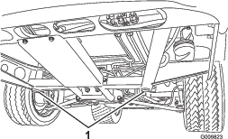
When jacking up the front of the machine, place a 2 x 4 block (or similar material) between the jack and the machine frame.
The jacking point at the front of the machine is under the front, center frame support (Figure 15).
Installing the Compression Spring
Parts needed for this procedure:
| Compression spring (black) | 2 |
-
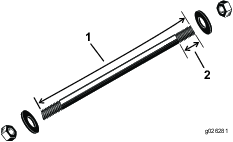
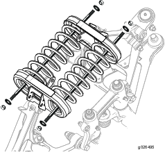
Using a compression spring tool as specified in Figure 17, install the compression spring rod through the holes in each spring cradle (Figure 18).
Important: Use caution when removing the spring cradle; the spring is under compression.
-
Measure and note the length of the springs.
-
Install the nuts and washers on both ends of the rod (Figure 19).
-
Tighten 1 nut on each rod to secure the springs (Figure 19).
-
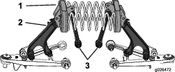
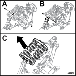
Remove the bolts and nuts from the end of each stabilizer link (A of Figure 20).
-
Remove the bolts and nuts from the control arm securing each spring cradle (B of Figure 20).
-
Remove the spring cradles and springs from the machine (C of Figure 20).
Note: Note the position of the decals on the spring cradles. The cradles need to be put back in the same location.
-
Remove the current springs from the spring cradles and place the springs from this kit (black springs) in the spring cradles.
-
Use the compression spring tool rod to compress the springs to the measurement taken in step 3.
-
Place the springs and cradle back into the machine.
-
Install the previously removed bolts and nuts from the stabilizer links and control arm.
-
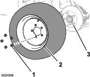
Install the front wheels and lower the machine.
-
Torque the lug nuts to 109 to 122 N∙m (80 to 90 ft-lb).
Installing the Inner Fender
Parts needed for this procedure:
| Inner fender | 1 |
| Fender strap | 2 |
| Hex-head flange bolt (1/4 x 3/4 inch) | 6 |
| Flange nut (1/4 inch) | 8 |
| Rubber bumper | 2 |
| Washer | 2 |
| Cable tie | 2 |
-
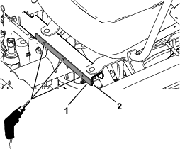
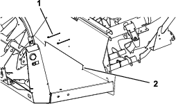
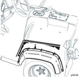
Align the fender straps at the bottom edge of the seat base frame, and use the fender straps as a template to mark and drill 3 holes (5/16 inch) on each side of the seat base frame (Figure 21).
-
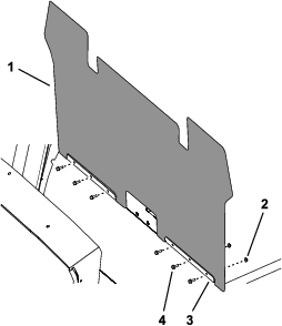
Install the inner fender and fenders straps using 6 hex-head flange bolts (1/4 x 3/4 inch) and 6 flange nuts (1/4 inch) as shown in Figure 22.
-
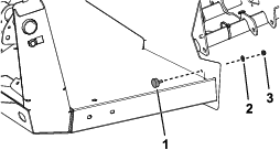
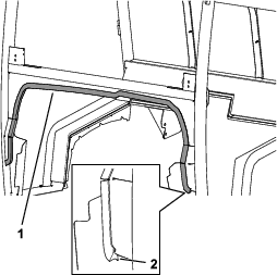
Fold down the flap and tuck the flap behind the floor flange (Figure 23).
-
Secure the flap with 2 cable ties around the center frame tube (Figure 23).
-
Install a rubber bumper using a washer and flange nut (1/4 inch) on each side (Figure 24).
Installing the Cab Mount Brackets
Parts needed for this procedure:
| Left mount assembly | 1 |
| Right mount assembly | 1 |
| Adjuster bolt (3/8 x 2 inches) | 2 |
| Hex nut (3/8 inch) | 2 |
| Hex-flange head bolt (3/8 x 1 inch) | 4 |
| Flange nut (3/8 inch) | 4 |
| Front cab mount bracket | 2 |
| Hex-head bolt (7/16 inch) | 2 |
| Thrust washer | 2 |
| Locknut (1/2 inch) | 2 |
| Rubber isolator | 2 |
| Spacer | 2 |
| Washer | 2 |
| Locknut | 2 |
| Flange-head bolt (1/2 x 2-1/4 inches) | 2 |
-
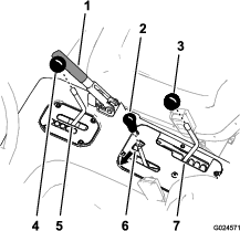
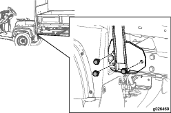
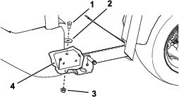
Install the rear brackets on the machine (Figure 25) using the hardware removed from the ROPS in Removing the ROPS Assembly.
-
Torque the bolts to 94 to 108 N∙m (70 to 80 ft-lb).
-
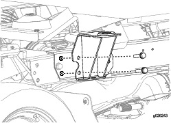
Install the left mount assembly and right mount assembly to the front cab mount brackets using 2 hex-flange head bolts (3/8 x 1 inch) and 2 flange nuts (3/8 inch) on each side (Figure 26).
Use the center holes in the mount assembly when installing.
-
Install the adjuster bolt (3/8 x 2 inches) and hex nut (3/8 inch) into the left mount assembly and right mount assembly on each side of the machine (Figure 26).
-
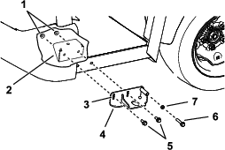
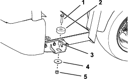
Install the front cab mount brackets using a hex-head bolt (7/16 inch), thrust washer, and locknut (1/2 inch) on each side (Figure 27).
-
Install the 2 rubber isolators using a flange-head bolt (1/2 x 2-1/4 inches), spacer, washer, and locknut on each side (Figure 28).
Note: Use soapy water to assist with installing the bracket-support mounts.
Installing the Seat Shroud
Both machines:
-
Align the opening in the seat shroud for the parking brake with the parking-brake handle.
-
Align the hole in the gear-selector boot with the rod for the gear selector.
-
Align the opening in the seat shroud for the rods for the lift bed control, high-low range shifter, and the differential lock.
-
Lower the seat shroud down.
-
Align the holes in the shroud for the seat mounting with the seat-support brackets of the chassis.
Do not tighten the bolts.
-
Plug in the shift indicator and secure the controls bracket with the screws (Figure 12 and Figure 14) removed in Removing the Seat Shroud.
Important: This step applies to Workman HDX-Auto machines only.
Installing the Side-Plate Panels and Cab Frame
Parts needed for this procedure:
| Side-plate panel | 2 |
| Cab frame | 1 |
| Bolt (1/2 inch) | 4 |
| Washer (1/2 inch) | 4 |
| Nut (1/2 inch) | 4 |
| Lower dash seal | 1 |
-
Loosen the bolts on the fenders approximately 1 turn to allow room for the side-plate panels to slide into place.
-
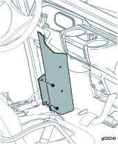
Slide the side-plate panels between the seat shroud and side fenders (Figure 29).
Note: Ensure that the panels are seated fully before tightening the bolts.
-
Tighten the bolts on the fenders.
Note: Do not overtighten the bolts.
-
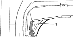
Install the lower dash seal to the cab (Figure 30).
Ensure that you install the seal with longer lip to the front (Figure 30).
-
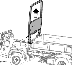
Hold the cab frame using the lifting points and place it on the machine (Figure 31).
Note: Before lowering the cab on to the machine, apply soapy water to the dash to keep the lower dash seal lubricated.
Note: Ensure that the front and rear lips on the lower dash seal do roll under during installation.
-
Secure the frame to the machine using the 4 bolts (1/2 inch), 4 washers (1/2 inch), and 4 nuts (1/2 inch) as shown in Figure 32.
Note: Do not tighten the 4 bolts (1/2 inch).
-
Adjust the cab from side to side to ensure that the cab is centered.
Use the adjuster bolt (Figure 26) to center the cab.
-
Torque the 4 bolts (1/2 inch) to 91 to 113 N∙m (67 to 83 ft-lb).
Routing the Wire Harness
Parts needed for this procedure:
| Wire harness | 1 |
| Cable ties | 4 |
| Fuse (30 A) | 1 |
-
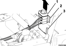
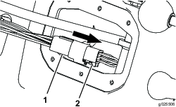
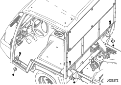
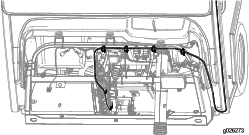
Route the wire harness as shown in Figure 33 and secure it with the 4 cable ties.
-
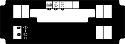
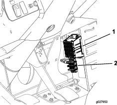
Connect the ring terminal on the harness to the grounding block and insert the fuse-block connector into an available fuse-block connection (Figure 34).
Note: If there is not an available fuse-block connection, you must add a fuse block to the fuse-block grouping. Contact your Authorized Service Dealer for more information.
Installing the Dash Support
Parts needed for this procedure:
| Back plate | 1 |
| Adjuster plate | 1 |
| Tap bolt (1/2 x 4 inches) | 1 |
| Flange nut (1/2 inch) | 1 |
| Stop plate | 1 |
| Carriage bolt (1/4 x 1-3/4 inches) | 4 |
| Flange nut (1/4 inch) | 4 |
-
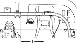
Measure 20.7 cm (8-1/8 inches) to the left from the bottom edge of the hood bracket and mark the location (Figure 35).
-
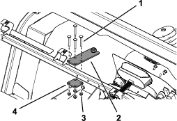
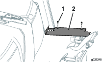
Install the adjuster plate and back plate to the dash-support tube using the 4 carriage bolts (1/4 x 1-3/4 inches) and flange nuts (1/4 inch) as shown in Figure 36.
-
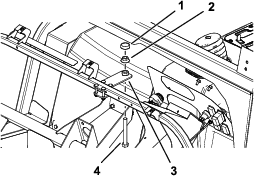
Install the tap bolt (1/2 x 4 inches), flange nut (1/2 inch), and stop plate to the adjuster plate (Figure 37).
-
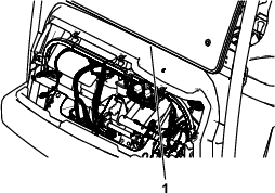
Close the gap between the dash and cab by adjusting the tap bolt (1/2 x 4 inches) until the stop plate pushes upward on the dash (Figure 38).
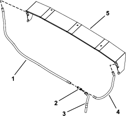
Installing the Water Gutter
Parts needed for this procedure:
| Water gutter | 1 |
| Passenger’s side clear tube—122 cm (48 inches) | 1 |
| Driver’s side clear tube—43 cm (17 inches) | 1 |
| Floor clear tube—33 cm (13 inches) | 1 |
| Tee fitting | 1 |
| Magnetic tie-wrap mount | 3 |
| Cable tie | 3 |
-
Remove the 5 hex-washer head bolts from the dash (Figure 39).
Retain the 5 hex-washer head bolts.
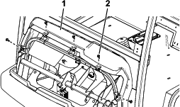
-
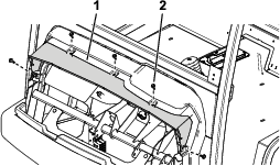
Slide the water gutter between the machine dash and sub-frame and secure the water gutter using the previously removed 5 hex-washer head bolts (Figure 40).
-
Using a tin snipper, remove the shipping tang from each side of the water gutter (Figure 41).
-
Connect the 122 cm (48 inches) clear tube to the 33 cm (13 inches) clear tube and 43 cm (17 inches) clear tube using the tee fitting (Figure 42).
-
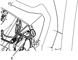
Starting from the passenger’s side, route the connected clear tube down through the floor board (with the clutch pedal) to the driver’s side of the machine (Figure 43).
-
Secure the connected clear tube with the 3 magnetic tie-wrap mounts and 3 cable ties (Figure 43).
-
Pinch each end of the clear tube and cut it at a 45° angle (Figure 44).
-
Align the clear tube with the bottom of the water gutter so that the top of the angle is to the outside of the machine and install it (Figure 44).
Installing the Floor and Side-Plate Panels
Parts needed for this procedure:
| Floor-plate panel | 2 |
| Side-plate panel | 2 |
| Bolt (1/4 inch) | 12 |
-
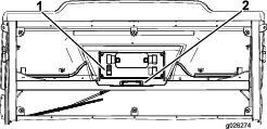
Install the floor-plate panels on each side of the machine using 3 bolts (1/4 inch) as shown in Figure 45.
-
Torque the bolts to 1017 to 1243 N∙cm (90 to 110 in-lb).
-
Install the side-plate panels on each side of the machine using 2 bolts (1/4 inch) as shown in Figure 46.
-
Torque the bolts to 1017 to 1243 N∙cm (90 to 110 in-lb).
Installing the Center Console Panel, Seats, Coolant Tank, CVT-Cooling Duct (HDX-Auto Machines only), and
Parts needed for this procedure:
| Bolt (1/4 inch) | 2 |
| Spacer | 2 |
| Strap | 1 |
| Nut (1/4 inch) | 2 |
| CVT-intake hood assembly (sold separately) | 1 |
-
Install the Operator’s Manual tube (Figure 47).
-
Align the holes in the seat rails with the holes in the shroud for the seat mounting positions (Figure 6).
-
Secure the seats to the chassis with the 8 socket-head bolts (Figure 6) that you removed in step Removing the Seats.
-
Secure the CVT-cooling duct (Figure 7) to the intake-tube connector using the hose clamp that you removed in Removing the CVT Cooling Duct (HDX-Auto Machines only), Coolant Tank, ROPS Assembly, and Seat Shroud.
Important: This step applies to Workman HDX-Auto machines only.
Note: You must add the CVT-intake hood assembly to this kit for Workman HDX-Auto machines. See your Authorized Service Dealer.
-
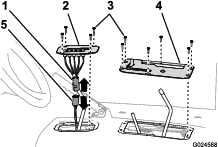
Align the center console panel over the control rods at the center console (Figure 3 and Figure 5) and secure the panel with the screws that you removed in Removing the Center Console Panel and Seats.
-
Install the knobs you removed in Removing the Center Console Panel and Seats.
-
Align the left and right flanges of the coolant-tank bracket with the coolant tank support on the seat shroud (Figure 8).
-
Lower the tank into the support until the tank is firmly seated (Figure 8).
Connecting the Battery, Lowering the Bed, and Installing the Hood
Refer to the Operator’s Manual for the machine.
-
Connect the positive battery cable to the battery.
-
Squeeze the battery cover, align the tabs to battery base, and release battery cover.
Note: Refer to the Operator’s Manual for the machine.
-
Lower the bed; refer to the Operator’s Manual.
-
Align the bottom of the hood to the top of the bumper.
-
Connect the lights.
-
Insert the top mounting tabs into the frame slots.
-
Insert the lower mounting tabs into the pockets in the bumper.
-
Ensure that the hood is fully engaged in the top, sides, and bottom grooves.
Product Overview
Control Panel
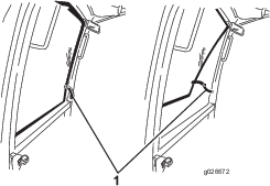
Windshield Latch
Lift up the latches to open the windshield (Figure 49). Press in the latch to lock the windshield in the open position. Pull the latch out and down to close and secure the windshield.