Safety
Rollover Protection System (ROPS) Safety
-
Do not remove the roll bar from the machine.
-
Ensure that the seat belt is attached and that you can release it quickly in an emergency.
-
Always wear your seat belt when the roll bar is up.
-
Check carefully for overhead obstructions and do not contact them.
-
Keep the roll bar in safe operating condition by thoroughly inspecting it periodically for damage and keeping all the mounting fasteners tight.
-
Replace a damaged roll bar. Do not repair or alter it.
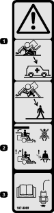
Safety and Instructional Decals
 |
Safety decals and instructions are easily visible to the operator and are located near any area of potential danger. Replace any decal that is damaged or missing. |
Installation
Note: Determine the left and right sides of the machine from the normal operating position.
Preparing the Machine
-
Park the machine on a level surface.
-
Disengage the blade-control switch.
-
Move the motion-control levers outward to the NEUTRAL-LOCK position.
-
Engage the parking brake.
-
Shut off the engine and remove the key.
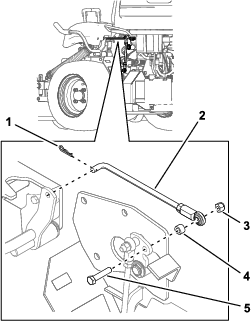
Disconnecting the PTO Linkage
Disconnect the PTO linkage from the PTO-engagement lever and from the PTO linkage to gain clear access to the mounting plate on the frame (Figure 1).
Note: Save the hardware.
Installing the Lower Support Tubes
Parts needed for this procedure:
| Right support tube | 1 |
| Left support tube | 1 |
| Hex-head screw (1/2 x 1-1/4 inches) | 6 |
| Spring washer (1/2 inch) | 6 |
| Serrated-flange nut (1/2 inch) | 6 |
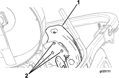
Loosely install the right roll bar and the left roll bar using the 6 hex-head screws (1/2 x 1-1/4 inches), 6 spring washers (1/2 inch), and 6 serrated-flange nuts (1/2 inch) as shown in Figure 2.
Important: To install the right roll bar, open the fuel tank to attain easier access.
Important: When installing the right support tube, ensure that the throttle cable and the choke cable (if equipped) do not get pinched between the console panel and the ROPS bracket.
Note: Ensure that the spring-washer cone is installed toward the head of all of the hex-head screws (Figure 2).
Installing the Upper, U-shaped Roll Bar
Parts needed for this procedure:
| Upper, U-shaped roll bar | 1 |
| Hex-head screw (1/2 x 3-1/4 inches) | 2 |
| Locknut (1/4 inch) | 2 |
| Locknut (1/2 inch) | 2 |
| Latch-pin assembly | 2 |
-
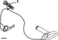
Locate the latch-pin assemblies (pin and hairpin connected with a lanyard).
-
Install a hex-head screw (1/2 x 3-1/4 inch) in the washer on the lanyard of each pin assembly.
Note: Ensure that the bent tab in the washer points toward the head of the hex-head screw (1/2 x 3-1/4 inch) as shown Figure 3.
-
Lightly oil the inside surfaces of the mounting plates at the upper end of the lower roll-bar tubes (Figure 4).
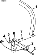
-
Locate the upper, U-shaped section of the roll bar, and install the upper roll-bar section using a hex-head screw (1/2 x 3-1/4 inch) and a locknut (1/2 inch) on each side (Figure 4).
Note: Ensure that the hex-head screws (1/2 x 3-1/4 inch) and the locknuts (1/2 inch) are installed with the nut to the inside of the roll bar.
Note: Make sure that the tab on the lanyard washer is installed and points toward the front of the unit.
-
Torque the hex-head screws (1/2 x 3-1/4 inch) and the locknuts (1/2 inch) to 91 to 113 N∙m (67 to 83 ft-lb).
-
Raise the roll bar into the upright position, install the latch pin (the oval handle must point toward the outside of the machine), and secure with the hairpin cotter on each side (Figure 4).
-
Torque all of the lower roll-bar hardware attached to the machine frame to 102 to 115 N∙m (75 to 85 ft-lb).
-
Close the fuel door and secure it to the frame.
-
Remove the left pod by removing the 3 hex-head screws (5/16 x 5/8 inch) as shown in Figure 5.
-
Install the PTO linkage through the left roll bar with the hardware that was retained in Disconnecting the PTO Linkage.
-
Install the left pod with the 3 hex-head screws (5/16 x 5/8 inch) as shown in Figure 5.
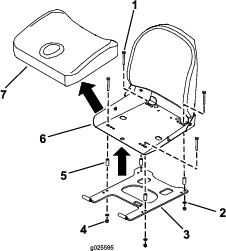
Removing the Existing Seat Frame
-
If the machine is equipped with a suspension seat, remove the seat, suspension system, and the adapters from the seat frame.
Note: Save the hardware.
-
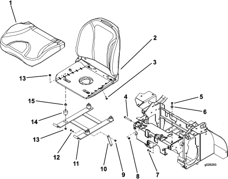
Remove the hardware from the seat-holdup linkage (Figure 6).
Note: Save the hardware.
-
Remove the 2 bolts and the 2 locknuts at the front of the seat where it is hinged (Figure 7).
Note: Save the hardware.
-
Unplug the seat-switch harness.
-
Remove the seat assembly and the frame from the machine (Figure 6).
-
Remove the seat cushion by the hex-head screws (5/16 x 1 inch) from the frame (Figure 6).
-
Remove the rubber isolators by removing the serrated-flange nuts (5/16 inch) as shown in Figure 6.
Note: Step 8 is not necessary if you are using a suspension system.
Note: Discard the seat frame and the rubber isolators.
Installing the New Seat Frame
Parts needed for this procedure:
| Seat-frame assembly | 1 |
| Hex-head screw (5/16 x 2-1/2 inches) | 4 |
| Washer (5/16 inch) | 4 |
| Serrated-flange nut (5/16 inch) | 4 |
| Spacer | 4 |
-
Install the seat onto the new seat frame with the 4 hex-head screws (5/16 x 2-1/2 inches), 4 washers (5/16 inch), 4 serrated-flange nuts (5/16 inch), and the 4 spacers (Figure 8).
-
Torque the 4 hex-head screws (5/16 x 2-1/2 inches) to 20 to 25 N∙m (175 to 225 in-lb).
-
If unit is equipped with a suspension system, install the seat, suspension system, and the adapters to the new seat frame.
Note: Refer to the installation instructions in the Suspension Seat Kit Manual.
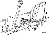
Installing the Seat Belt
Parts needed for this procedure:
| Hex-head screw (7/16 x 1 inch) | 2 |
| Locknut (7/16 inch) | 2 |
-
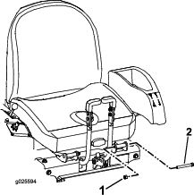
Install the receiver portion of the seat belt between the cushion and the metal seat frame with a hex-head screw (7/16 x 1 inch) and a locknut (7/16 inch) as shown in Figure 9.
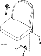
-
Torque the locknut (7/16 inch) to 66 to 83 N∙m (49 to 61 ft-lb).
-
Install the long seat-belt strap between the cushion and the metal seat frame with a hex-head screw (7/16 x 1 inch) and a locknut (7/16 inch).
-
Torque the locknut (7/16 inch) to 66 to 83 N∙m (49 to 61 ft-lb).
-
Install the bottom seat cushion (Figure 6).
Installing the Seat onto the Machine
-
Install the seat assembly onto the machine at the hinges with the 2 bolts and the 2 locknuts that were removed in step 4 of Removing the Existing Seat Frame.
-
Attach the hold-up linkage with the nut and the bolt removed in step 3 of Removing the Existing Seat Frame.
-
Plug in the seat-switch harness.
Checking the Seat-frame Latch
-
If the seat-frame latch does not latch easily, ensure that the seat mounting deck is as far rearward as possible.
-
Loosen the 5 hex-head screws (5/16 x 5/8 inch) that secure the seat deck to the machine frame (3 on the top, 2 in the front) as shown in Figure 6.
-
Using a rubber or plastic mallet, tap the front of the seat-mounting deck at the mounting-bolt locations, moving the mounting deck to the rear position.
-
Torque the 5 hex-head screws (5/16 x 5/8 inch) to 20 to 25 N∙m (175 to 225 in-lb).
Operation
Using the Rollover Protection System (ROPS)
Warning
There is no rollover protection when the roll bar is down. Wheels dropping over edges, ditches, steep banks, or water can cause a rollover, which may result in serious injury or death.
-
Keep the roll bar in the raised and locked position, and use the seat belt.
-
Lower the roll bar only when necessary.
-
Do not wear the seat belt when the roll bar is down.
-
Drive slowly and carefully.
-
Raise the roll bar as soon as clearance permits.
Check carefully for overhead clearances (i.e. branches, doorways, and electrical wires) before driving under any objects, and do not contact these objects.
Check the rollover protection system (roll bar) pins.
-
Make sure that the latch pin and hairpin are fully installed and that the lanyard is in good condition.
-
Ensure that the seat latch closes and latches securely.
-
Check the operation and condition of seat belt. If the seat belt webbing is worn or frayed, replace it immediately.
In the event of a rollover, take the machine to the manufacturer to have the ROPS inspected.