Disclaimers and Regulatory Information
This product complies with all relevant European directives; for details, please see the separate product specific Declaration
of Conformity (DOC) sheet.
It is a violation of California Public Resource Code Section 4442 or 4443 to use or operate the engine on any forest-covered,
brush-covered, or grass-covered land unless the engine is equipped with a spark arrester, as defined in Section 4442, maintained
in effective working order, or the engine is constructed, equipped, and maintained for the prevention of fire.
The enclosed engine owner's manual is supplied for information regarding the US Environmental Protection Agency (EPA) and
the California Emission Control Regulation of emission systems, maintenance, and warranty. Replacements may be ordered through
the engine manufacturer.
Operating this machine 1,500 m (5,000 ft) above sea level requires a high-altitude jet. Refer to your Honda engine owner’s manual.
 |
| |
| CALIFORNIA |
| |
| Proposition 65 |
| |
| The engine exhaust from this product contains chemicals known to
the State of California to cause cancer, birth defects, or other reproductive
harm. |
| |
| Use of this product may cause exposure to chemicals known to the
State of California to cause cancer, birth defects, or other reproductive
harm. |
| |
Intended Use
This machine is a walk-behind, reel-blade lawn mower intended to be used by professional, hired operators in commercial applications.
It is primarily designed for cutting grass on well-maintained turf. Using this product for purposes other than its intended
use could prove dangerous to you and bystanders.
Read this information carefully to learn how to operate and maintain your product properly and to avoid injury and product
damage. You are responsible for operating the product properly and safely.
Getting Help
Visit www.Toro.com for product safety and operation training materials, accessory information, help finding a dealer, or to register your product.
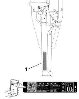
Whenever you need service, genuine Toro parts, or additional information, contact an Authorized Service Dealer or Toro Customer Service and have the model and serial numbers of your product ready. These numbers are located on the serial plate
on your product  . Write the numbers in the space provided.
With your mobile device, you can scan the QR code on the serial number decal (if equipped) to access warranty, parts, and
other product information.
|
Model Number:
|
|
Serial Number:
|
|
Manual Conventions
This manual identifies potential hazards and has safety messages identified by the safety-alert symbol, which signals a hazard
that may cause serious injury or death if you do not follow the recommended precautions.
This manual uses 2 words to highlight information. Important calls attention to special mechanical information and Note emphasizes general information worthy of special attention.
General Safety
This product is capable of amputating hands and feet and of throwing objects.
- Read and understand the contents of this Operator’s Manual before starting the machine.
- Use your full attention while operating the machine. Do not engage in any activity that causes distractions; otherwise, injury
or property damage may occur.
- Do not put your hands or feet near moving components of the machine.
- Do not operate the machine without all guards and other safety protective devices in place and functioning properly on the
machine.
- Keep bystanders and children out of the operating area. Never allow children to operate the machine.
- Shut off the engine, remove the key (if equipped), and wait for all movement to stop before you leave the operator’s position. Allow the machine to cool before adjusting, servicing, cleaning, or storing it.
Improperly using or maintaining this machine can result in injury. To reduce the potential for injury, comply with these safety
instructions and always pay attention to the safety-alert symbol  , which means Caution, Warning, or Danger—personal safety instruction. Failure to comply with these instructions may result in personal injury or death.
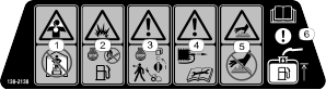
Safety and Instructional Decals
 |
Safety decals and instructions are easily visible to the operator and are located near any area of potential danger. Replace
any decal that is damaged or missing.
|
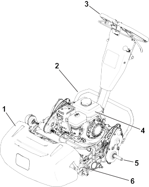
G406958
- Grass basket
- Kickstand
- Handle
- Fuel tank
- Transport wheel axle
- Cutting unit
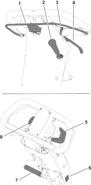
Controls
G406959
-
Clutch bail
-
Cutting-unit-drive lever
-
Parking-brake latch
-
Service-brake lever
-
Throttle control
-
Hour meter
-
Lift-assist handle
-
On/Off switch
Clutch Bail
Use the clutch bail to engage or disengage the traction drive.
- Engage the traction drive
 : Pull up and hold the bar to the handle.
- Disengage the traction drive
 : Release the bar.
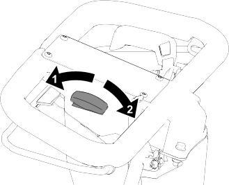
Reel Speed Control
Use the reel-speed-control knob to engage adjust the reel speed.
- High reel speed: Rotate the knob so that the “H” on the knob is directed toward the front of the machine.
- Low reel speed: Rotate the knob so that the “L” on the knob is directed toward the front of the machine.
Throttle Control
- Decrease the engine speed : Rotate the lever up.
- Increase the engine speed
 : Rotate the lever down.
On/Off Switch
- Start the engine : Push the upper part of the switch.
- Shut off the engine : Push the lower part of the switch.
Service-Brake Lever
Pull the service-brake lever toward the handle to slow or stop the machine.
Parking-Brake Latch
- Engage the parking brake : Rotate the parking-brake latch toward you while the service-brake lever is engaged.
- Disengage the parking brake : Pull the service-brake lever toward the handle.
Cutting-Unit-Drive Lever
Use the cutting-unit-drive lever to engage or disengage the cutting unit while the clutch bail is engaged.
- Engage the cutting unit : Move the lever down.
- Disengage the cutting unit : Move the lever up.
Hour Meter
The hour meter records the total running time of the engine to assist in scheduling regular maintenance.
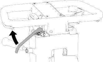
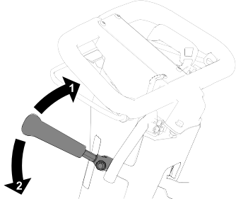
Handle-Height Adjuster
Pull up on the handle-height adjuster and raise or lower the handle height to a comfortable operating position.
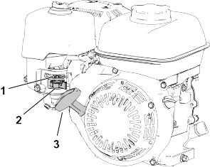
Engine Controls
G404703
-
Choke lever
-
Fuel-shutoff valve
-
Recoil-starter handle
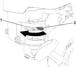
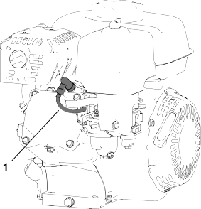
Choke Lever
G404704
- Engage the choke before starting a cold engine.
- Disengage the choke when the engine is warm.
Fuel-Shutoff Valve
Close the fuel-shutoff valve when the machine is not used for a few days, during transport to and from the job site, or when
the machine is parked inside a building.
Recoil-Starter Handle
Pull the recoil-starter handle to start the engine.
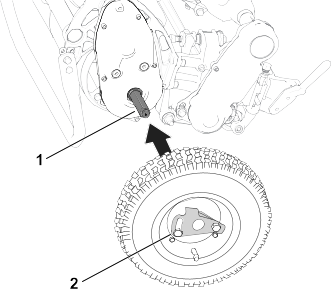
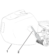
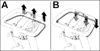
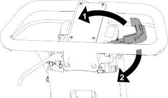
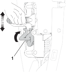
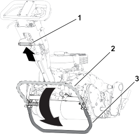
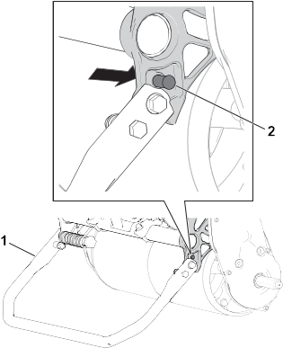
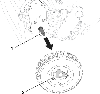
Kickstand
Use the kickstand when you install or remove the transport wheels or the cutting unit.
 |
Caution |
|
The machine is heavy and can cause back strain if lifted improperly.
Put your foot pressure down on the kickstand and use only the lift-assist handle to raise the machine. Attempting to raise
the machine onto the kickstand any other way can cause injury.
G404706
- Kickstand—Cutting-Unit Service position
- Spring pin
Specifications
Note: Specifications and design are subject to change without notice.
|
Width
|
84 cm (33 inches)
|
91 cm (36 inches)
|
104 cm (41 inches)
|
|
Dry weight*
|
95 kg (210 lb)
|
100 kg (220 lb)
|
107 kg (235 lb)
|
|
Width of cut
|
46 cm (18 inches)
|
53 cm (21 inches)
|
66 cm (26 inches)
|
|
Height of cut
|
Dependent on traction-drum position and use of High Height-of-Cut Kit.
|
|
Clip
|
Dependent on reel speed and reel-drive-pulley position.
|
|
Engine speed
|
Low idle: 1,900 ± 100 rpm; High idle: 3,450 ± 100 rpm
|
|
Mowing speed
|
3.2 km/h (2 mph) to 5.6 km/h (3.5 mph)
|
|
Transport speed
|
8.5 km/h (5.3 mph)
|
|
*Traction unit only. Refer to the cutting unit Operator’s Manual for the weight of each cutting unit.
|
Attachments/Accessories
A selection of Toro approved attachments and accessories is available for use with the machine to enhance and expand its capabilities. Contact
your Authorized Service Dealer or authorized Toro distributor or go to www.Toro.com for a list of all approved attachments and accessories.
To ensure optimum performance and continued safety certification of the machine, use only genuine Toro replacement parts and accessories.
|
Warning |
|
Failure to properly maintain the machine could result in premature failure of machine systems, causing possible harm to you
or bystanders.
Keep the machine well maintained and in good working order as indicated in these instructions.
Note: Determine the left and right sides of the machine from the normal operating position.
Do not tip the machine at an angle greater than 25°. Tipping the machine beyond 25° leads to oil leaking into the combustion
chamber and/or fuel leaking out of the fuel-tank cap.
Refer to your engine owner’s manual for additional maintenance procedures.
Maintenance Safety
- Before you leave the operator’s position, do the following:
- Park the machine on a level surface.
- Move the throttle to the low-idle position.
- Disengage the cutting unit(s).
- Ensure that the traction is in neutral.
- Engage the parking brake.
- Shut off the machine and remove the key (if equipped).
- Wait for all movement to stop.
- Allow machine components to cool before performing maintenance.
- If possible, do not perform maintenance while the machine is running. Keep away from moving parts.
- If the engine must be running to perform a maintenance adjustment, keep your hands, feet, clothing, and any parts of the body
away from the cutting unit, attachments, and any moving parts. Keep bystanders away.
- Clean grass and debris from the cutting unit, drive, muffler, cooling screen, and the engine to help prevent fires. Clean
up oil or fuel spills.
- Keep all parts in good working condition. Replace all worn, damaged, or missing parts and decals. Keep all hardware tight
to ensure that the machine is in safe working condition.
- Check the grass catcher components frequently and replace them when necessary.
- To ensure safe, optimal performance of the machine, use only genuine Toro replacement parts. Replacement parts made by other manufacturers could be dangerous, and such use could void the product
warranty.
- If major repairs are ever needed or if assistance is desired, contact an authorized Toro distributor.
Recommended Maintenance Schedule
|
After the first 20 hours
|
|
38280 |
1 |
Bottle of oil |
|
Before each use or daily
|
|
- |
- |
- |
|
|
- |
- |
- |
|
Every 50 hours
|
|
- |
- |
- |
|
Every 100 hours
|
|
38280 |
1 |
Bottle of oil |
|
|
- |
1 |
Spark plug; obtain from Honda |
|
Every 300 hours
|
|
- |
1 |
Paper filter element; obtain from Honda |
|
|
- |
1 |
Spark plug; obtain from Honda |
|
Yearly
|
|
- |
- |
- |
Daily Maintenance Checklist
Duplicate this page for routine use.
|
Check the brake-lock-lever operation.
|
|
|
|
|
|
|
|
|
Check the fuel level.
|
|
|
|
|
|
|
|
|
Check the engine-oil level.
|
|
|
|
|
|
|
|
|
Check the air filter.
|
|
|
|
|
|
|
|
|
Clean the engine cooling fins.
|
|
|
|
|
|
|
|
|
Check for unusual engine noises.
|
|
|
|
|
|
|
|
|
Check for unusual operating noises.
|
|
|
|
|
|
|
|
|
Check the reel-to-bedknife adjustment.
|
|
|
|
|
|
|
|
|
Check the height-of-cut adjustment.
|
|
|
|
|
|
|
|
|
Touch up damaged paint.
|
|
|
|
|
|
|
|
|
Clean the machine.
|
|
|
|
|
|
|
|
Notation for Areas of Concern
Pre-Maintenance Procedures
Preparing the Machine for Maintenance
|
Warning |
|
While you are maintaining or adjusting the machine, someone could start the engine. Accidentally starting the engine could
seriously injure you or other bystanders.
Release the clutch bail, engage the parking brake, and pull the wire off the spark plug before you do any maintenance. Also
push the wire aside so that it does not accidentally contact the spark plug.
-
Park the machine on a level surface.
-
Shut off the engine.
-
Engage the parking brake.
-
Wait for all moving parts to stop and allow the engine to cool before servicing, storing, or making repairs.
-
Disconnect the spark-plug wire .
Engine Maintenance
Engine Safety
- Do not change the governor speed or overspeed the engine.
- Run the engine dry or remove the fuel with a hand pump; never siphon the fuel. If you must drain the fuel tank, do it outdoors.
Engine Oil Specifications
|
Crankcase capacity:
|
0.56 L (19 fl oz)
|
|
Oil type:
|
API classification SJ or later.
|
|
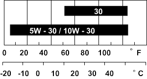
Oil viscosity:
|
Select the oil viscosity according to ambient temperature in the table below.
Note: Multi-grade oils (5W-30 and 10W-30) increase oil consumption. Check the engine-oil level more frequently when you use these
oils.
|
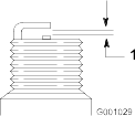
Checking the Engine-Oil Level
The ideal time to check the engine-oil level is when the engine is cool or before you have started the engine for the day.
If you have already ran the engine, allow the oil to drain back down to the sump for at least 10 minutes before you check
the engine-oil level.
-
Shut off the engine and wait for all moving parts to stop.
-
Position the machine so that the engine is level, and clean the area around the oil-fill tube .
-
Remove the dipstick by rotating it counterclockwise.
-
Remove the dipstick and wipe the end clean.
-
Insert the dipstick fully into the oil-fill tube, but do not thread it in.
-
Remove the dipstick and check the engine-oil level.
-
If the engine-oil level is incorrect, add or drain oil to correct the level.
Note: If the oil level is near or below the lower level mark  on the dipstick, add only enough of the specified oil to raise the level to the upper limit mark
  (bottom edge of the oil fill hole)
Changing the Engine Oil
|
Warning |
|
Oil may be hot after the engine has been run, and contact with hot oil can cause severe personal injury.
Avoid contacting the hot engine oil when you drain it.
-
Shut off the engine and wait for all moving parts to stop.
-
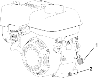
Place a pan under the drain plug to catch the oil.
-
Remove the drain plug, washer , and dipstick .
-
Position the engine so that the oil drains from the engine.
-
When the oil has drained completely, move the engine to a level position and install the drain plug and a new washer.
Note: Dispose of the used oil at a certified recycling center.
-
Slowly pour oil into the oil-fill hole until the oil is at the correct level.
-
Ensure that the oil is at the correct level on the dipstick.
-
Thread the dipstick into the oil-fill hole.
-
Wipe up any spilled oil.
-
Connect the wire to the spark plug.
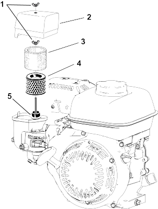
Servicing the Air Cleaner
Do not operate the engine without the air filter assembly; extreme engine damage will occur.
-
Shut off the engine and wait for all moving parts to stop.
-
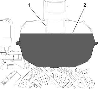
Remove the wingnut securing the air-cleaner cover .
-
Remove the air-cleaner cover.
Ensure that no dirt or debris from the air-cleaner cover fall into the base.
-
Remove the foam element and paper element from the base.
-
Remove the foam element from the paper element.
-
Inspect the foam and paper elements; replace them if they are damaged or excessively dirty.
-
Clean the paper element by tapping it gently to remove the dirt.
Do not try to brush dirt off the paper element; brushing forces the dirt into the fibers. Replace the element if tapping it
fails to remove the dirt.
-
Clean the foam element in warm, soapy water or in a nonflammable solvent.
Do not use gasoline to clean the foam element because it could create a risk of fire or explosion.
-
Rinse and dry the foam element thoroughly.
-
Wipe dirt from the base and the cover with a moist rag.
Ensure that dirt and debris do not enter the air duct  leading to the carburetor.
-
Install the air-cleaner elements and ensure that they are properly positioned. Install the lower wing nut.
-
Install the cover and install the upper wing nut to secure it.
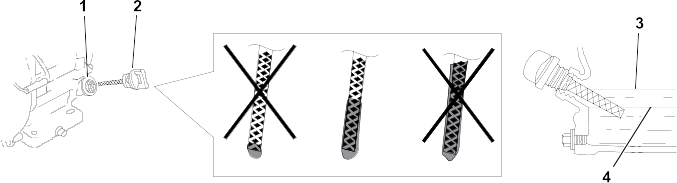
Servicing the Spark Plug
Use an NGK BPR6ES spark plug or equivalent.
-
Shut off the engine and wait for all moving parts to stop.
-
Clean around the spark plug.
-
Remove the spark plug from the cylinder head.
Replace a cracked, fouled, or dirty spark plug. Do not sand blast, scrape, or clean the electrodes because engine damage could
result from grit entering the cylinder.
-
Set the gap on the plug to 0.7 to 0.8 mm (0.028 to 0.031 inch).
-
Carefully install the spark plug by hand (to avoid cross threading) until it is hand tight.
-
Tighten the spark plug an additional 1/2 turn if it is new; otherwise, tighten it an additional 1/8 to 1/4 turn.
A loose spark plug can become very hot and can damage the engine; overtightening a spark plug may damage the threads in the
cylinder head.
-
Connect the wire to the spark plug.
Controls Maintenance
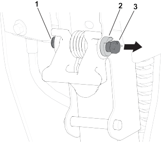
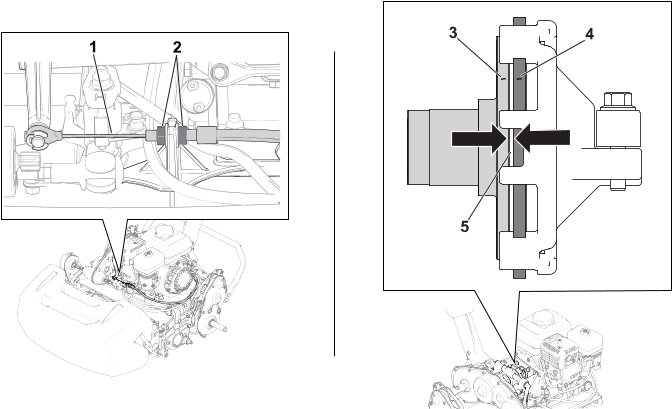
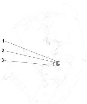
Adjusting the Reel-Control Cable
Adjust the reel-control cable to remove additional slack.
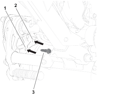
-
Move the reel-speed-control knob to the high-reel-speed position.
-
Loosen the rear jam nut and tighten the front jam nut .
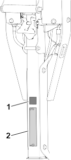
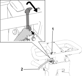
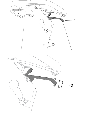
Adjusting the Throttle Cable
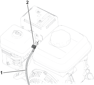
Adjusting the Low-Idle Engine Speed
-
Park the machine on a level surface and engage the parking brake.
-
Ensure that the engine is at a normal operating temperature.
-
Start the engine and use the throttle control to decrease the engine speed to low idle.
-
Use a tachometer to observe the low-idle engine speed.
The ideal range for low idle is 1,800 to 2,000 rpm.
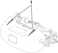
-
Loosen the conduit clamp on the throttle cable .
-
Move the cable conduit until you observe 1,900 rpm on the tachometer.
-
Tighten the screw on the cable-conduit clamp.
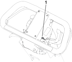
Adjusting the High-Idle Engine Speed
-
Park the machine on a level surface and engage the parking brake.
Note: Ensure that the engine is at a normal operating temperature before you adjust the throttle cable.
-
Start the engine and use the throttle control to increase the engine speed to high idle.
-
Use a tachometer to observe the high-idle engine speed.
The ideal range for high idle (for use in non-CE-compliant countries) is 3,350 to 3,550 rpm. If the tachometer shows a speed below 3,350 or above 3,550 rpm, perform the following steps in this procedure until you
attain a speed between 3,350 to 3,550 rpm.
-
Shut off the engine.
-
Adjust the throttle-control stop per the high-idle reading on your tachometer.
- To increase the high-idle-speed threshold, move the throttle-control stop up.
- To decrease the high-idle-speed threshold, move the throttle-control stop down.
-
Start the engine and observe the new high-idle reading.
If the tachometer shows the appropriate speed, the adjustment is completed.
Cutting Unit Maintenance
Blade Safety
- Use care when checking the reel cutting-unit. Wear gloves and use caution when servicing the reel.
- A worn or damaged blade or bedknife can break, and a piece could be thrown toward you or bystanders, resulting in serious
personal injury or death.
- Inspect the blades and bedknives periodically for excessive wear or damage.
- Use care when checking the blades. Wear gloves and use caution when servicing them. Only replace or backlap the blades and
bedknives; never straighten or weld them.
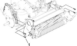
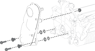
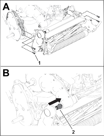
Installing the Cutting Unit
Installing the Cutting Unit
Model 04820 Only
-
Move the kickstand to the Cutting-Unit-Service position.
-
Remove the hardware that secures the reel-drive assembly to the side plate.
-
Remove the reel-drive assembly, flat washers, spring washers, and spacers from the side plate.
-
Align the cutting unit to the frame.
-
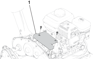
Use 4 socket-head screws to secure the cutting unit to the frame.
-
Use the previously removed socket-head screws, washers, and spacers to secure the reel-drive assembly to the cutting-unit
side plate.
Ensure that the reel-drive-assembly driveshaft is installed to the transmission-driveshaft coupler .
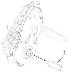
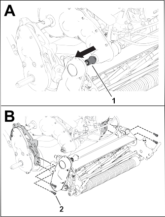
Installing the Cutting Unit
Models 04830 and 04840 Only
-
Move the kickstand to the Cutting-Unit-Service position.
-
Align the cutting unit to the frame.
-
Use 4 socket-head screws to secure the cutting unit to the frame.
-
Slide the cutting-unit-drive coupler onto the transmission driveshaft.
The coupler should slide onto the transmission driveshaft without resistance. If there is resistance, ensure that the reel
driveshaft and the transmission driveshaft are aligned
-
Install the grass basket.
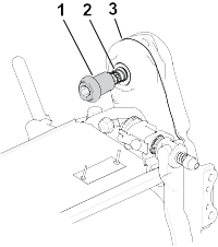
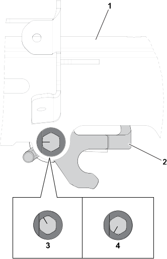
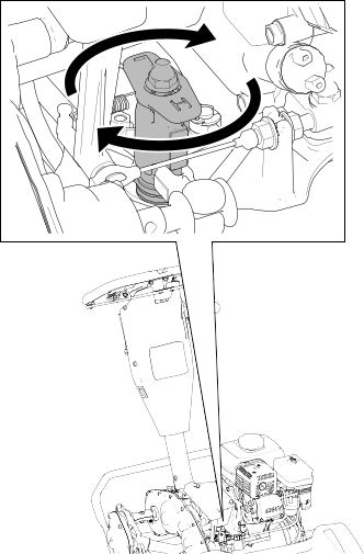
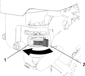
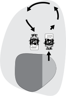
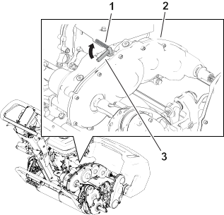
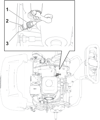
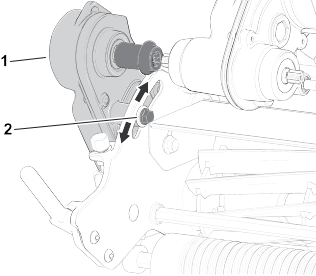
Adjusting the Reel-Driveshaft Position
Note: If you feel resistance between the coupler and the driveshaft when installing the cutting unit, perform this procedure to
adjust the driveshaft.
-
Loosen the bolt .
-
Rotate the reel-drive assembly so that the reel driveshaft is properly aligned with the transmission driveshaft.
-
Tighten the bolt that you previously loosened.
If resistance continues, adjust the engine and transmission alignment; refer to the adjustment procedure in the traction unit
Service Manual.
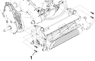
Removing the Cutting Unit
Removing the Cutting Unit
Model 04820 Only
-
Move the kickstand to the Cutting-Unit-Service position.
-
Remove the grass basket (if equipped).
-
Remove the reel-drive assembly from the cutting unit and retain the hardware.
-
Remove the socket-head screws that secure the cutting unit to the frame.
-
Remove the cutting unit from the frame.
Removing the Cutting Unit
Models 04830 and 04840 Only
-
Move the kickstand to the Cutting-Unit-Service position.
-
Remove the grass basket (if equipped).
-
Release the cutting-unit-drive coupler from the transmission driveshaft.
-
Remove the socket-head screws that secure the cutting unit to the frame.
-
Remove the cutting unit from the frame.
Backlapping Information
|
Access Backlap Kit (Model 139-4342)
|
Models 04820, 04830, and 04840
|
|
Backlap Kit (Model 04800)
|
Models 04830 and 04840
|
Refer to the operating instructions in the specific kit Installation Instructions. Contact your authorized Toro distributor to acquire one of these kits.