Disclaimers and Regulatory Information
This product complies with all relevant European directives; for details, please see the separate product specific Declaration
of Conformity (DOC) sheet.
 |
| |
| CALIFORNIA |
| |
| Proposition 65 |
| |
| The power cord on this product contains lead, a chemical known to
the State of California to cause birth defects or other reproductive
harm. Wash hands after handling. |
| |
| Battery posts, terminals, and related accessories contain lead and
lead compounds, chemicals known to the State of California to cause
cancer and reproductive harm. Wash hands after handling. |
| |
| Use of this product may cause exposure to chemicals known to the
State of California to cause cancer, birth defects, or other reproductive
harm. |
| |
Intended Use
This machine is a walk-behind, reel-blade lawn mower intended to be used by professional, hired operators in commercial applications.
It is primarily designed for cutting grass on well-maintained turf. Using this product for purposes other than its intended
use could prove dangerous to you and bystanders.
Read this information carefully to learn how to operate and maintain your product properly and to avoid injury and product
damage. You are responsible for operating the product properly and safely.
Getting Help
Visit www.Toro.com for product safety and operation training materials, accessory information, help finding a dealer, or to register your product.
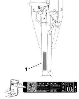
Whenever you need service, genuine Toro parts, or additional information, contact an Authorized Service Dealer or Toro Customer Service and have the model and serial numbers of your product ready. These numbers are located on the serial plate
on your product  . Write the numbers in the space provided.
With your mobile device, you can scan the QR code on the serial number decal (if equipped) to access warranty, parts, and
other product information.
|
Model Number:
|
|
Serial Number:
|
|
Manual Conventions
This manual identifies potential hazards and has safety messages identified by the safety-alert symbol, which signals a hazard
that may cause serious injury or death if you do not follow the recommended precautions.
This manual uses 2 words to highlight information. Important calls attention to special mechanical information and Note emphasizes general information worthy of special attention.
General Safety
This product is capable of amputating hands and feet and of throwing objects.
- Read and understand the contents of this Operator’s Manual before starting the machine.
- Use your full attention while operating the machine. Do not engage in any activity that causes distractions; otherwise, injury
or property damage may occur.
- Do not put your hands or feet near moving components of the machine.
- Do not operate the machine without all guards and other safety protective devices in place and functioning properly on the
machine.
- Keep bystanders and children out of the operating area. Never allow children to operate the machine.
- Shut off the machine, remove the key (if equipped), and wait for all movement to stop before you leave the operator’s position. Allow the machine to cool before adjusting, servicing, cleaning, or storing it.
Improperly using or maintaining this machine can result in injury. To reduce the potential for injury, comply with these safety
instructions and always pay attention to the safety-alert symbol  , which means Caution, Warning, or Danger—personal safety instruction. Failure to comply with these instructions may result in personal injury or death.
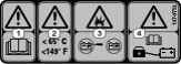
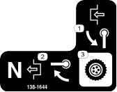
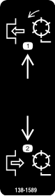
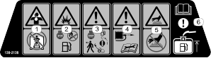
Safety and Instructional Decals
 |
Safety decals and instructions are easily visible to the operator and are located near any area of potential danger. Replace
any decal that is damaged or missing.
|
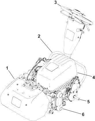
G407048
- Grass basket
- Kickstand
- Handle
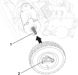
- Battery pack
- Transport-wheel axle
- Cutting unit
Controls
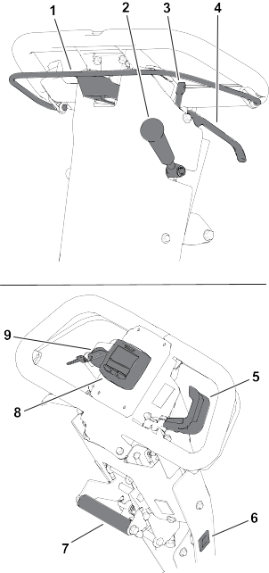
G407032
-
Clutch bail
-
Cutting-unit-drive lever
-
Parking-brake latch
-
Service-brake lever
-
Speed control
-
Hour meter
-
Lift-assist handle
-
InfoCenter
-
Key switch
Clutch Bail
Use the clutch bail to engage or disengage the traction drive.
- Engage the traction drive
 : Pull up and hold the bar to the handle.
- Disengage the traction drive
 : Release the bar.
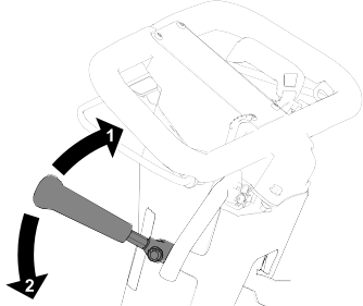
Speed Control
- Decrease the motor speed : Rotate the lever up.
- Increase the motor speed
 : Rotate the lever down.
Reel Speed Control
Use the reel-speed-control knob to engage adjust the reel speed.
- High reel speed: Rotate the knob so that the “H” on the knob is directed toward the front of the machine.
- Low reel speed: Rotate the knob so that the “L” on the knob is directed toward the front of the machine.
Key Switch
- Start the machine: Move the key to the On position.
- Shut off the machine: Move the key to the Off position.
Service-Brake Lever
Pull the service-brake lever toward the handle to slow or stop the machine.
Parking-Brake Latch
- Engage the parking brake : Rotate the parking-brake latch toward you while the service-brake lever is engaged.
- Disengage the parking brake : Pull the service-brake lever toward the handle.
Cutting-Unit-Drive Lever
Use the cutting-unit-drive lever to engage or disengage the cutting unit while the clutch bail is engaged.
- Engage the cutting unit : Move the lever down.
- Disengage the cutting unit : Move the lever up.
Hour Meter
The hour meter records the total running time of the engine to assist in scheduling regular maintenance.
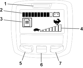
InfoCenter LCD Display
The InfoCenter LCD display shows information about your machine such as the current battery charge, the speed, various diagnostics,
and other information about the machine and the battery. The following figure illustrates the InfoCenter and the main information
screen.
- Power light/fault indicator —illuminates when you turn the machine on. This light also blinks when there is a machine fault.
- Battery charge indicator —when the battery has a full charge, all of the boxes in the indicator will be filled in with black. As power is used, boxes
will be filled with white starting from the right and proceeding to the left as the battery drains. When only 1 box is still
black the battery pack is almost out of power; the machine enters a power reduction mode which limits the throttle speed by
25%. You should immediately proceed to charge the battery.
- Fault log indicator
 —this icon indicates that there is a current fault log to review.
- Speed control setting
 —the bars turn black from left to right the faster you set the speed control. When all bars are filled with white, the machine
is at zero speed.
—the bars turn black from left to right the faster you set the speed control. When all bars are filled with white, the machine
is at zero speed.
- Menu access/back button
 —press this button to access the InfoCenter menus. You can also use it to back out of any menu you are currently using.
- Down button
 —use this button to scroll down menus.
- Right button
 —use this button to open a menu where a right arrow indicated additional content.
Note: The purpose of each button may change depending on what is required at the time. Each button has a label with an icon displaying
its current function.
InfoCenter Menu Items
Main Menu
|
Faults
|
The Faults menu contains a list of the recent machine faults. Refer to the Service Manual or your authorized Toro distributor for more information on the Faults menu.
|
|
Service
|
The Service menu contains information on the machine such as hours of use and battery usage and status.
|
|
Diagnostics
|
The Diagnostics menu lists various states that the machine currently has. You can use this to troubleshoot certain issues
as it will quickly tell you which machine controls are on and which are off.
|
|
Settings
|
The Settings menu allows you to customize the InfoCenter display.
|
|
About
|
The About menu lists the model number, serial number, and software version of your machine.
|
Service Menu
|
Hours
|
Lists the total number of hours that the machine has been turned on.
|
|
Mow Time
|
Lists the total number of hours that the reel has been turned on.
|
|
Power Use
|
Lists the instantaneous power delivered by the battery in Watts.
|
|
Battery Charge
|
Lists the current battery charge as a percent of capacity.
|
|
Battery Current
|
Lists the instantaneous current delivered by the battery in Amps.
|
|
Battery Volts
|
Lists the battery potential in volts.
|
|
Total Usage
|
Lists the total amount of battery usage in amp hours.
|
|
Capacity
|
List the current battery capacity in amp hours.
|
|
Charge Cycles
|
Lists the total amount of battery charge cycles. A charge cycle is defined by the process of connecting and disconnecting
the charger.
|
|
Battery Hours
|
Lists the total amount of hours that the battery has been active.
|
|
Backlap
|
Sets the machine in Backlap Mode.
|
|
Energy
|
Lists the total energy delivered by the battery over its entire life in watt-hours.
|
Diagnostics Menu
|
Key On
|
Indicates whether the ignition key is on or off.
|
|
Traction
|
Indicates whether the traction is engaged or disengaged.
|
|
Throttle
|
Indicates the throttle control setting in Volts (used to calculate the target rpm).
|
|
Bail
|
Indicates the bail control settings in volts.
|
|
Target rpm
|
Lists the desired motor rpm as indicated by the speed control setting.
|
|
Motor rpm
|
Lists the actual motor rpm.
|
|
12V Supply
|
Lists the sensor supply voltage #1 of the controller.
|
|
5V Supply
|
Lists the sensor supply voltage #2 of the controller.
|
|
CAN Bus
|
Lists the machine communication bus status.
|
Settings Menu
|
Language
|
Use this setting to change the language used on the InfoCenter.
|
|
Units
|
Use this setting to change the units used by the InfoCenter. The menu choices are English and Metric.
|
|
LCD Backlight
|
Use this setting to increase or decrease the brightness of the LCD display.
|
|
LCD Contrast
|
Use this setting to change the contrast between the dark and light areas of the LCD display.
|
About Menu
|
Model
|
Lists the model number of the machine.
|
|
SN
|
Lists the serial number of the machine.
|
|
S/W Rev
|
Lists the revision number of the machine software.
|
Note: If you inadvertently change the language or contrast to a setting where you can no longer understand or view the display,
contact your authorized Toro distributor for assistance in resetting the display.
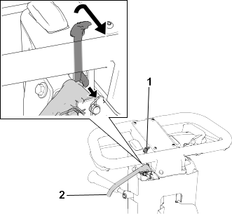
Handle-Height Adjuster
Pull up on the handle-height adjuster and raise or lower the handle height to a comfortable operating position.
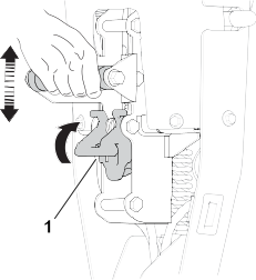
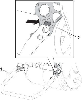
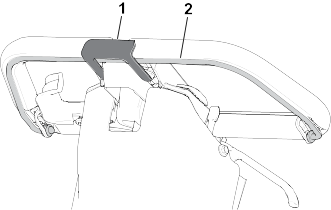
Kickstand
Use the kickstand when you install or remove the transport wheels or the cutting unit.
 |
Caution |
|
The machine is heavy and can cause back strain if lifted improperly.
Put your foot pressure down on the kickstand and use only the lift-assist handle to raise the machine. Attempting to raise
the machine onto the kickstand any other way can cause injury.
G404706
- Kickstand—Cutting-Unit Service position
- Spring pin
Specifications
Note: Specifications and design are subject to change without notice.
|
Width
|
91 cm (36 inches)
|
|
Dry weight*
|
97 kg (207 lb)
|
|
Width of cut
|
53 cm (21 inches)
|
|
Height of cut
|
Refer to your cutting unit Operator’s Manual.
|
|
Clip
|
Dependent on reel speed and reel-drive-pulley position.
|
|
Mowing speed
|
3.2 km/h (2 mph) to 5.6 km/h (3.5 mph)
|
|
Transport speed
|
8.5 km/h (5.3 mph)
|
|
*Traction unit only. Refer to the cutting unit Operator’s Manual for the weight of each cutting unit.
|
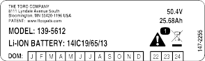
Electrical Specifications
|
Voltage
|
48 V
|
|
Current
|
DC ( ) )
|
|
Amp Hours
|
25.6 AH
|
|
IP Rating
|
IP65
|
Attachments/Accessories
A selection of Toro approved attachments and accessories is available for use with the machine to enhance and expand its capabilities. Contact
your Authorized Service Dealer or authorized Toro distributor or go to www.Toro.com for a list of all approved attachments and accessories.
To ensure optimum performance and continued safety certification of the machine, use only genuine Toro replacement parts and accessories.
|
Warning |
|
Failure to properly maintain the machine could result in premature failure of machine systems, causing possible harm to you
or bystanders.
Keep the machine well maintained and in good working order as indicated in these instructions.
Note: Determine the left and right sides of the machine from the normal operating position.
Do not tip the machine at an angle greater than 25°. Tipping the machine beyond 25° leads to oil leaking into the combustion
chamber and/or fuel leaking out of the fuel-tank cap.
Refer to your engine owner’s manual for additional maintenance procedures.
Maintenance Safety
- Before you leave the operator’s position, do the following:
- Park the machine on a level surface.
- Disengage the cutting unit(s).
- Ensure that the traction is in neutral.
- Engage the parking brake.
- Shut off the machine and remove the key (if equipped).
- Wait for all movement to stop.
- Allow machine components to cool before performing maintenance.
- If possible, do not perform maintenance while the machine is running. Keep away from moving parts.
- If the machine must be on to perform a maintenance adjustment, keep your hands, feet, clothing, and any parts of the body
away from the cutting unit, attachments, and any moving parts. Keep bystanders away.
- Clean grass and debris from the cutting unit, drive, motor, and battery to help prevent fires.
- Keep all parts in good working condition. Replace all worn, damaged, or missing parts and decals. Keep all hardware tight
to ensure that the machine is in safe working condition.
- Check the grass catcher components frequently and replace them when necessary.
- To ensure safe, optimal performance of the machine, use only genuine Toro replacement parts. Replacement parts made by other manufacturers could be dangerous, and such use could void the product
warranty.
- If major repairs are ever needed or if assistance is desired, contact an authorized Toro distributor.
Recommended Maintenance Schedule
|
Before each use or daily
|
|
- |
- |
- |
|
Every 750 hours
|
|
505-183 |
1 |
Dexron VI synthetic transmission fluid (18.9 L or 5 US gallons) |
|
Yearly
|
|
- |
- |
- |
Daily Maintenance Checklist
Duplicate this page for routine use.
|
Check the brake-lock-lever operation.
|
|
|
|
|
|
|
|
|
Check for unusual operating noises.
|
|
|
|
|
|
|
|
|
Check the reel-to-bedknife adjustment.
|
|
|
|
|
|
|
|
|
Check the height-of-cut adjustment.
|
|
|
|
|
|
|
|
|
Touch up damaged paint.
|
|
|
|
|
|
|
|
|
Clean the machine.
|
|
|
|
|
|
|
|
Notation for Areas of Concern
Pre-Maintenance Procedures
Preparing the Machine for Maintenance
|
Warning |
|
While you are maintaining or adjusting the machine, someone could start the machine. Accidentally starting the machine could
seriously injure you or other bystanders.
Release the traction bail, engage the parking brake, remove the key, and disconnect the battery before you do any maintenance.
-
Park the machine on a level surface.
-
Engage the parking brake.
-
Shut off the machine.
-
Wait for all moving parts to stop before servicing, storing, or making repairs.
-
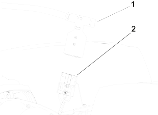
Disconnect the battery by pulling the T-handle connector off of the main-power connector .
Electrical System Maintenance
Electrical System Safety
- Disconnect the battery before repairing the machine.
- Charge the battery in an open, well-ventilated area, away from sparks and flames. Unplug the charger before connecting or
disconnecting the battery. Wear protective clothing and use insulated tools.
Servicing the Lithium-Ion Battery
The only user serviceable parts in the battery pack are the labels. If you are having problems with your battery, contact
your authorized Toro distributor for help.
|
Warning |
|
The battery contains high voltage, which could burn or electrocute you.
- Do not attempt to open the battery.
- Do not place anything in the battery connector other than the wire-harness connector that came with the product.
- Use extreme care when handling a battery with a cracked case.
- Only use the charger designed for the battery.
Battery Disposal
The lithium-ion battery must be disposed of or recycled in accordance with local and federal regulations.
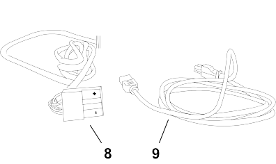
Maintaining the Battery Charger
All electrical repairs should be performed by an authorized Toro distributor only.
The operator can perform very little maintenance other than protecting the charger from damage and weather.
- Clean the charger cords and case with a slightly damp cloth after each use.
- Coil the cords when not in use.
- Periodically examine the cords for damage, and replace them when necessary with Toro-approved parts.
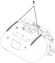
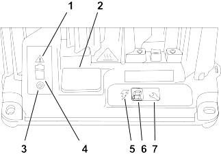
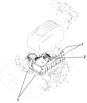
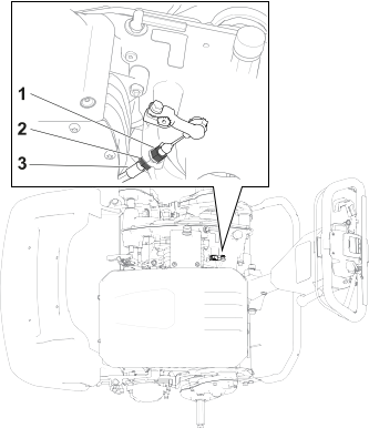
Replacing Fuses
If the machine does not turn on, even after charging, check the machine fuses as follows:
-
Turn off the machine and disconnect the battery pack.
-
Remove the 4 screws that secure the battery-pack cover and remove the cover.
-
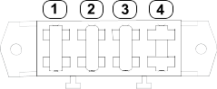
Check the fuses in the fuse block .
G404909
-
30A—main power supply circuits
-
3A—logic power supply circuits
-
3A—optional LED work light circuit
-
Open slot
-
If any fuse is blown, replace them with a fuse of the appropriate voltage and amperage. Refer to the traction unit Service Manual for specific fuse part numbers.
All fuses on the machine are rated for 80V. Do not use 12V automotive fuses.
Drive System Maintenance
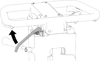
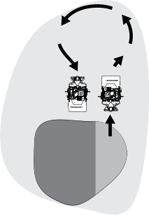
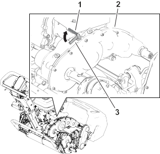
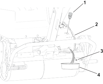
Changing the Transmission Fluid
-
Remove the breather vent and adapter assembly from the transmission.
-
Have an assistant tip the machine backwards and place a pan under the transmission.
Note: Use the pan to collect the transmission fluid.
-
Remove the drain plug from the transmission and let the fluid drain out.
-
Install the drain plug.
-
Torque the drain plug to 4 to 5 N∙m (32 to 42 in-lb).
-
Add 473 ml (16 fl oz) of Dexron VI synthetic transmission fluid through the adapter vent.
-
Install the breather vent and adapter assembly and tighten it to 12 to 15 N∙m (110 to 130 in-lb).
Cutting Unit Maintenance
Blade Safety
- Use care when checking the reel cutting-unit. Wear gloves and use caution when servicing the reel.
- A worn or damaged blade or bedknife can break, and a piece could be thrown toward you or bystanders, resulting in serious
personal injury or death.
- Inspect the blades and bedknives periodically for excessive wear or damage.
- Use care when checking the blades. Wear gloves and use caution when servicing them. Only replace or backlap the blades and
bedknives; never straighten or weld them.
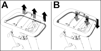
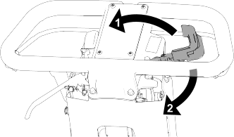
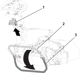
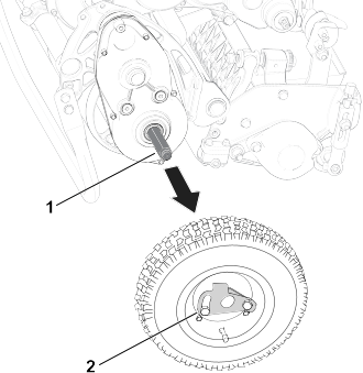
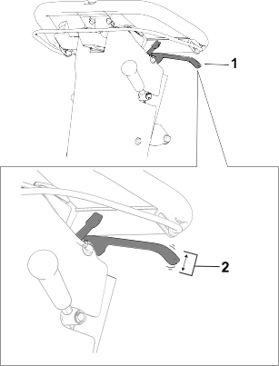
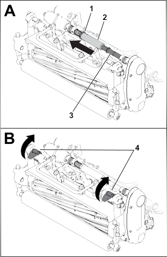
Installing the Cutting Unit
-
Move the kickstand to the Cutting-Unit-Service position.
-
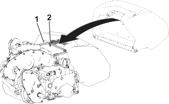
Align the cutting unit to the frame.
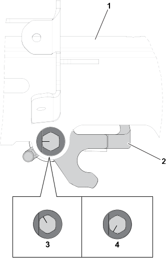
-
Move the suspension latches down to secure the cutting unit to the machine.
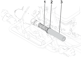
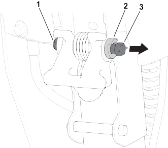
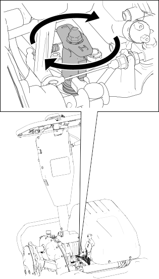
-
Move the collar out of the transmission-coupler-shaft groove and insert the hex tube into the cutting-unit coupler shaft .
-
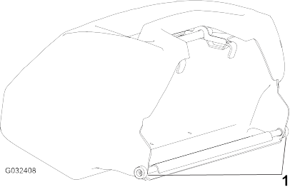
Install the grass basket.
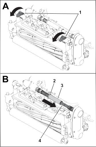
Removing the Cutting Unit
Note: The hex tube disengages if you engage the reel drive when the cutting unit is removed.
-
Move the kickstand to the Cutting-Unit-Service position.
-
Remove the grass basket (if equipped).
-
Move the collar into the transmission-shaft groove.
Note: This releases tension from the spring.
-
Slide the hex tube off of the cutting-unit coupler shaft .
-
Move the suspension latches up to release the cutting unit from the machine.
-
Remove the cutting unit from the frame.
Backlapping Information
To backlap the cutting unit, perform 1 of the following options:
Cleaning
Cleaning the Machine
After each use, wash the machine with mild detergent and water. Do not pressure wash the machine. Avoid excessive use of water,
especially near the shift-lever plate, the InfoCenter, the power center, and the machine power connector. Clean the motor
to provide proper cooling during operation. Also, keep the battery pack as clean as possible so that it maintains a white
color. This reflects sunlight and keeps the battery from overheating in the sun.
Do not use brackish or reclaimed water to clean the machine.
Always store or park the machine out of direct sunlight, as heating from the sun reduces the battery-pack life span.
Storage Safety
- Shut off the machine, remove the key (if equipped), and wait for all movement to stop before you leave the operator’s position. Allow the machine to cool before adjusting, servicing, cleaning, or storing it.
- Do not store the machine where there is an open flame, spark, or pilot light, such as on a water heater or other appliance.
Storing the Machine
-
Clean the machine.
You can wash the machine with mild detergent and fresh clean water. Do not pressure-wash the machine. Avoid excessive use
of water, especially near the shift-lever plate, the InfoCenter, the power center, and the machine power connector.
-
Check and tighten all fasteners. Repair or replace any part that is worn or damaged.
-
Paint all scratched or bare metal surfaces with paint available from your authorized Toro distributor.
-
For prolonged storage, follow the battery storage requirements.
-
Cover the machine to protect it and keep it clean.
Battery Storage Requirements
Note: You do not need to remove the battery from the machine for storage.
Refer to the temperature requirements for storage in the following table:
Temperature Requirements for Storage
| Storage Conditions |
Temperature Requirement |
| Normal storage conditions |
-20° to 45°C (-12° to 113°F) |
| Extreme heat—1 month or less |
45° to 60°C (113° to 140°F) |
| Extreme cold—3 months or less |
-30° to -20°C (-22° to -12°F) |
Temperatures outside of this range will damage your battery.
The temperature that the battery are stored at will affect their long-term life. Storage for long periods of time at extreme
temperatures will reduce the battery life. Store the machine in a cool (not below freezing) location.
- Before you store the machine, charge or discharge the battery between 40% to 60% (50.7V to 52.1V).
Note: A 50% charge is optimal to ensure a maximum battery life. When the battery is charged to 100% before storage, the battery
life shortens.
If you anticipate that the machine will be stored for a longer period of time, charge the battery to around 60%.
- For every 6 months of storage, check the battery-charge level and ensure that it is between 40% to 60%. If the charge is below
40%, charge the battery between 40% to 60%.
- You can use a multimeter to check the charge level when the machine is off. Refer to the following table for the amount of
voltage that is equal to the charge level:
| Voltage |
Charge Level |
| 52.1V |
60% |
| 51.4V |
50% |
| 50.7V |
40% |
- After charging the battery, disconnect the battery charger from power. Disconnect the power connector during storage to minimize
the discharging of the battery.
- If you leave the charger on the machine, it will shut off after the battery is fully charged and does not turn back on unless
the charger is disconnected and reconnected.
Storing the Charger
-
Disconnect the charger from the machine.
-
Disconnect the power-supply cord from the charger and coil it securely.
-
Examine the power supply cord thoroughly for signs of wear or damage. Replace it if it is worn or damaged.
-
Examine the charger thoroughly for worn, loose, or damaged parts. To repair or replace parts, contact your authorized Toro distributor for assistance.
-
Store the charger with the power supply cord in a clean, dry place where it will not be bumped or damaged and not exposed
to caustic fumes.