Safety
Safety and Instructional Decals
 |
Safety decals and instructions are easily visible to the operator and are located near any area of potential danger. Replace any decal that is damaged or missing. |

Installation
Preparing the Machine
-
Park the machine on a level surface with enough area to lower the booms.
-
Engage the parking brake.
-
Lower the booms.
-
Shut off the engine and remove the key.
-
Wait for all moving parts to stop.
-
Allow the engine to cool.
Installing the Fan Guard
Parts needed for this procedure:
| Front fan guard | 1 |
| Rear fan guard | 1 |
| Carriage bolt (5/16 x 3/4 inch) | 4 |
| Flange locknut (5/16 inch) | 4 |
| Capscrew (5/16 x 2-3/4 inches) | 2 |
| Washer (3/8 x 7/8 inch) | 2 |
| Spacer | 4 |
Removing the Air-Cleaner Hose
-
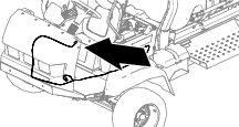
Rotate both seats forward and secure them with the prop rods.
-
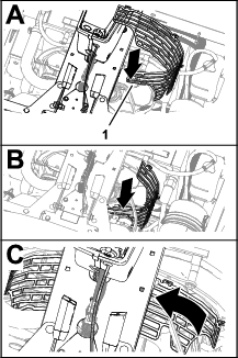
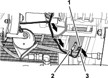
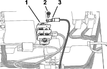
Below the passenger seat area, remove the 2 hose clamps that secure the air-cleaner hose to the vent T-tube and the throttle-body inlet (Figure 1).
-
Remove the air-cleaner hose from the vent tube and throttle body.
Installing the Forward Fan Guard
-
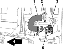
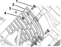
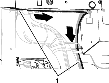
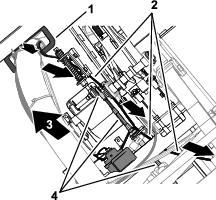
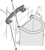
Remove the 2 capscrews (5/16 x 3/4 inch), 2 lock washers (5/16), and 2 washers (5/16) that secure the upper fan shroud (Figure 2).
Note: Discard the capscrews, lock washers, and washers.
-
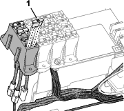
Position the forward fan guard under the center console.
-
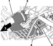
Align the holes on the forward fan guard with the holes in the fan shroud (Figure 3).
-
Install the guard to the shroud (Figure 3) with the 4 spacers, 2 washers (5/16 inch), and 2 capscrews (5/16 x 2-3/4 inches).
Installing the Rear Fan Guard
Installing the Intake Air Duct
-
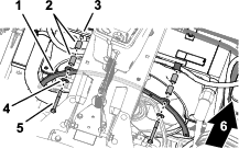
Assemble the air-cleaner hose onto the T-vent tube and the throttle-body inlet (Figure 6).
-
Secure the air-cleaner hose to the vent tube and throttle body with the 2 hose clamps (Figure 6) that you removed in Removing the Air-Cleaner Hose.
Installing the Horn Switch
Parts needed for this procedure:
| Horn switch (switch, jam nut, and knurled nut) | 1 |
| Wire harness | 1 |
-
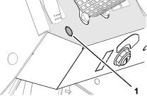
Remove the knock-out plug from the dash panel (Figure 7).
-
Remove any burrs from the hole.
-
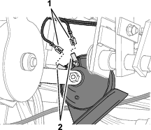
Thread the jam nut onto the horn switch (Figure 8).
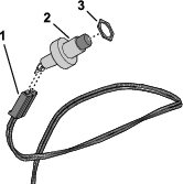
-
Plug the horn switch into the 2-socket connector labeled of the kit wire harness (Figure 8).
-
From the bottom of the panel, insert the switch through the hole (Figure 9).
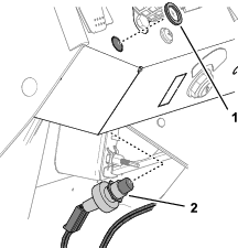
-
If needed, adjust the jam nut to position so that you expose enough threads of the horn switch to install the knurled nut (Figure 9).
-
Secure the horn switch to the dash panel with the knurled nut (Figure 9).
Installing the Horn
Parts needed for this procedure:
| Horn | 1 |
| Capscrew (5/16 x 3/4 inch) | 1 |
| Flange locknut (5/16 inch) | 1 |
-
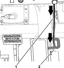
Assemble the bracket of the horn to the clutch plate (Figure 10) with a capscrew (5/16 x 3/4 inch) and a flange locknut (5/16 inch).
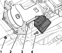
-
Torque the capscrew and locknut to 1978 to 2542 N∙cm (175 to 225 in-lb).
Installing the Kit Wire Harness
Parts needed for this procedure:
| Cable ties | 6 |
Routing the Harness through the Floor
Connecting the Harness to the Horn
-
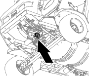
Route the kit wire harness rearward, along the traction-control cable (Figure 15).
-
Route the 2 wires with the spade-terminal sockets to the horn (Figure 16).
-
Plug the terminal sockets labeled and into the spade terminals of the horn (Figure 16).
Note: Either wire terminal socket can connect to either horn terminal.
Routing the Harness to the Electrical Panel
-
At the left side of the radiator, route connectors labeled and of the kit wire harness up and rearward, pushing the connectors through the overlapping foam blocks (Figure 17).
-
Secure the kit wire harness to the chassis with 2 cable ties.
-
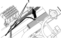
Pull the kit wire harness toward the fuse block as shown in Figure 18.
Connecting the Kit Wire Harness to the Ground Block and Fuse Block
Customer supplied part: Fuse (10 A)—fast-acting ATC/ATO blade type
-
Remove one terminal screws from the ground block (Figure 19).
-
Install the ring terminal labeled of the kit wire harness to the ground block with the terminal screw (Figure 19).
-
Plug the insulated spade connector labeled of the fuse block into the spade terminal labeled of the kit wire harness (Figure 20).

-
Secure the kit wire harness to the machine wire harness with 2 cable ties.
-
Insert the fuse (10 A) into the fuse block slot for the connector (Figure 21).
-
Secure the kit wire harness to the machine wire harness with 2 cable ties.
-
Rotate the seats down.
Installing the Personal Protective Equipment Storage Bag
Parts needed for this procedure:
| PPE storage bag | 1 |
| Hoop rod | 1 |
| Mount bracket | 1 |
| U-bolt | 1 |
| Flange locknut (3/8 inch) | 2 |
-
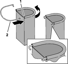
Insert a hoop rod into the sleeve of the PPE storage bag as shown in Figure 22.
-
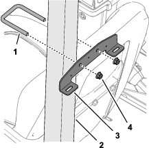
Install the mount bracket to the rollbar tube (Figure 23) with a U-bolt and 2 flange locknuts (3/8 inch).
Note: Ensure that the bracket location does not cover the rollbar decals.
-
Insert the hooks of the hoop rod into the slots in the mount bracket (Figure 24).
Installing the Decals
Parts needed for this procedure:
| Folding boom decal (104-8904) | 2 |
| Tank contents-slate decal (119-9434) | 1 |
| Regulatory decal | 1 |
Applying the Folding Boom Decals
-
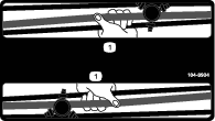
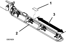
Measure from the end of the booms as shown in Figure 25.
-
Clean the truss tube of the boom at the area where you measured in step 1.
Note: Ensure that the tube surface is free of dirt, grease, or other foreign material.
-
Remove the backing from the folding boom decal (104-8904), and adhere it to the truss tube of the boom (Figure 25).
-
Repeat steps 1 through 3 at the other boom.
Applying the Tank Contents-Slate Decal
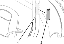
Apply the erasable tank contents-slate decal (119-9434) onto the ROPS bar to install.
Note: The magnetic backing of the contents-slate decal allows it to affix to any ferrous metal surface.Position the tank contents-slate decal on the roll bar behind the operator's seat.
Applying the Regulatory Decal
-
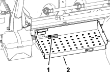
Clean the surface of the step below the model-serial plate and the emissions decal.
-
Remove the backing from the regulatory decal, and adhere it to the step.
-
Adhere the regulatory decal below the emissions decal.