Safety
Safety and Instructional Decals
 |
Safety decals and instructions are easily visible to the operator and are located near any area of potential danger. Replace any decal that is damaged or missing. |

Installation
Preparing the Machine
-
Park the machine on a level surface.
-
Engage the parking brake.
-
Shut off the engine and remove the key.
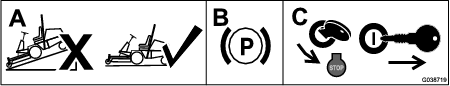
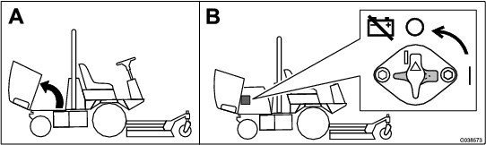
Disconnecting the Battery
Turn the battery-disconnect switch to the OFF position.
Installing the Wire Harness
Parts needed for this procedure:
| Wire harness | 1 |
| Switch | 1 |
| Auxiliary-brake decal | 1 |
-
Remove the 6 bolts from the console and remove the panel (Figure 3).

-
Disconnect the connectors from the hazard switch and turn-signal switch (Figure 3).
-
Remove the knockout from the control panel and install the switch (Figure 4).

-
Adhere the auxiliary-brake decal above the switch (Figure 4).
-
Connect the new wire harness to the hazard switch, turn-signal switch, and auxiliary-brake switch (Figure 5).

-
Connect the wire harness to the machine main wire harness inside the console (Figure 5).
-
Install the panel (Figure 3).
Installing the Headlights (for Machines with ROPS only)
Parts needed for this procedure:
| Right light bracket | 1 |
| Left light bracket | 1 |
| Grommet | 2 |
-
Unplug the wire harness from each existing headlight.
-
Remove the headlights and retain lights and hardware.
-
Remove the brackets from the headlights and discard the brackets (Figure 6).
-
Using the fasteners that you removed, install the left and right light brackets to the existing holes in the front of the operator’s platform (Figure 6).
-
Using existing fasteners from the headlight assembly, install the headlights to the left and right light brackets (Figure 6).
-
Install the grommets to the light mounts (Figure 6).
-
Route the wire harness through the bottom of the light brackets and out the grommets.
-
Connect the harness to each headlight.

Installing the Headlights (for Machines with a Cab Only)
Parts needed for this procedure:
| Right light bracket | 1 |
| Left light bracket | 1 |
| Right headlight assembly | 1 |
| Left headlight assembly | 1 |
| Bolt (1/2 x 1 inch) | 2 |
| Nut (1/2 inch) | 2 |
| Bolt (1/4 x 3/4 inch) | 2 |
| Nut (1/4 inch) | 2 |
| Grommet | 2 |
-
Unplug the wire harness from each existing headlight.
-
Remove the headlights and retain the hardware.
-
Remove and discard the existing bracket.
-
Install the grommets to the light mounts.
-
Install each headlight bracket to the cab frame using 1 bolt (1/2 x 1 inch), 1 nut (1/2 inch), 1 bolt (1/4 x 3/4 inch), and 1 nut (1/4 inch) as shown in Figure 7.
-
Remove the fasteners from the headlight assemblies and use them to install the headlights to the brackets.
-
Route the wire harness through the bottom of light brackets and out the grommets.
-
Connect the wire harness to each headlight (Figure 7).

Installing the Light Plate and License Bracket
Parts needed for this procedure:
| Plate light | 1 |
| License bracket | 1 |
| Sign mount | 1 |
| Screw Screw (#10 x 3/4 inch) | 2 |
| Speed nut | 2 |
| Carriage bolt (1/4 x 5/8 inch) | 2 |
| Nut (1/4 inch) | 2 |
| Decal (20) |
-
Remove the cover under the rear bumper (Figure 8).

-
Remove the existing warning sign and the mount tube from the rear bumper (Figure 9).
Note: Do not remove the bolts from the bumper.
-
Cut the cable tie holding the wire for the plate light.
-
Use the hardware to install the sign mount to the bumper (Figure 9).
-
Install the 2 speed nuts to the square in the license bracket.
-
Install the license bracket to the sign mount with 2 carriage bolts (1/4 x 5/8 inch) and 2 nuts (1/4 inch).
-
Route the wire to the plate light and connect it to the light.
-
Install the plate light to the license bracket using 2 screws (#10 x 3/4 inch) and the speed nuts in the license bracket.

-
Adhere a sign to the license bracket (Figure 9).
Installing the Rear Lights
Parts needed for this procedure:
| Pivot bracket | 2 |
| Light mount | 2 |
| Right tube mount | 1 |
| Left tube mount | 1 |
| Left light housing | 1 |
| Right light housing | 1 |
| Inner mount | 2 |
| Carriage bolt (5/16 x 3/4 inch) | 4 |
| Carriage bolt (1/4 x 5/8 inch) | 4 |
| Nut (1/4 inch) | 10 |
| Nut (5/16 inch) | 4 |
| Bolt (1/4 x 3/4 inch) | 6 |
| Hex-socket button head screw (1/4 x 3/4 inch) | 8 |
| Bolt (1/2 x 1-1/2 inch) | 4 |
-
Unplug the wire harness from both tail lights.
-
Remove the tail lights from the machine.
-
Remove the brackets from the rear bumper and discard the brackets and hardware (Figure 10).
-
Remove the bottom 2 bolts (1/2 x 1-1/4 inch), on each side, that secure the bumper to the machine frame.
-
Install a pivot bracket to each side of the machine with 2 bolts (1/2 x 1-1/2 inch); refer to Figure 10.
-
Install a light mount to each pivot bracket with 6 bolts (1/4 x 3/4 inch) and 6 nuts (1/4 inch).
-
Install the left and right tube mount to each light mount with 4 carriage bolts (5/16 x 3/4 inch) 4 nuts (5/16 inch).
-
Install the left and right light housings to the left and right tube mounts (Figure 10).
-
Secure the light housings to the tube mounts with 2 carriage bolts (1/4 x 5/8 inch) and 2 nuts (1/4 inch).
-
Secure the existing lights with the yellow lens on top to each inner mount with the existing phillips-head screws.
-
Route the harness connectors through each tube mount, housing, and plug the connectors into the lights.
-
Slide the inner mounts into the housings and secure them with 8 hex-socket button head screws (1/4 x 3/4 inch).

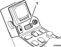
Verifying that the Machine is in CE Mode
-
Start the machine.
-
From the InfoCenter main menu, navigate to the About screen (Figure 11).

-
Verify that the machine is in CE mode. If it is not in CE mode; contact your authorized Toro distributor.
Operation
Using the Light and Hazard Switches
-
Turn the key switch on and press the light switch to the ON position to activate the head lamps.
-
Press the hazard switch to the ON position to activate the front and rear flashing hazard lights.
-
Turn the key switch on and press the left side of the turn signal switch to activate the left turn signal and the right side of the switch to activate the right turn signal. The center position is off.
Note: Check the operation of the lights. Make sure that the correct lights are flashing when operating the turn signal switch.
Aiming the Headlights
-
Loosen the mounting nuts to adjust the lights.
-
Adjust the lights per local standards.
Using the Auxiliary-Brake Switch
Press and hold the auxiliary-brake switch to decrease the engine speed (Figure 12); release the switch to stop the deceleration and remain at the current engine speed.
Note: You may use the switch intermittently to gradually slow the machine.
If you press the switch when the engine speed is below 1,200 rpm or if the engine decelerates to 1,200 rpm, the engine shuts off and the machine stops. To start the machine again, turn the key switch to the START position and release it immediately when the engine starts.