Note: The Foam Marker Kit is required for the installation of this product. Contact your Authorized Toro Dealer for more information.
Safety
Note: Determine the left and right sides of the machine from the normal operating position.
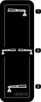
Safety and Instructional Decals
 |
Safety decals and instructions are easily visible to the operator and are located near any area of potential danger. Replace any decal that is damaged or missing. |
Installation
Preparing the Machine
Park the machine to a level surface, engage the parking brake, shut off the engine, and remove the key from the key switch.
Disconnect the battery; refer to the Operator’s Manual.
Installing the Foam-Marker Compressor on the Bracket
Parts needed for this procedure:
| Bracket | 1 |
| Bolt (5/16 x 1 inch) | 4 |
| Washer (3/8 inch) | 4 |
| Nut (5/16 inch) | 4 |
| Foam marker (sold separately) | 1 |
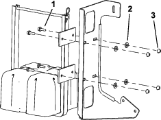
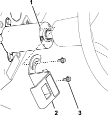
Install the foam-marker compressor onto the bracket as shown in Figure 1.
Installing the Compressor and Bracket on the Machine
Parts needed for this procedure:
| Carriage bolt | 1 |
| U-bolt | 1 |
| Flange nuts (3/8 inch) | 3 |
| Spacer | 1 |
| R-clamp | 1 |
-
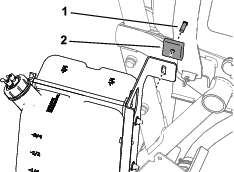
Loosen the bolt on the top of the strap and place the carriage bolt through the strap of the sprayer tank belt (Figure 2).
-
Slide the spacer onto the bolt and place the bracket onto the bolt as shown in Figure 2.
-
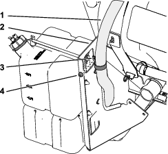
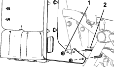
Put the pump suction hose through the R-clamp (Figure 3).
-
Secure the R-clamp to the bolt with a nut (Figure 3).
-
Place the U-bolt onto the machine as shown in Figure 4.
-
Place the bracket onto the U-bolt and secure it with the 2 flange nuts (3/8 inch).
Routing the Wire Harness and Installing the Switches
Parts needed for this procedure:
| Wire harness | 1 |
| Switch bracket | 1 |
| Rocker switch | 1 |
| Paddle switch | 1 |
| Bolts (M6) | 2 |
| Fuse, 15 amp | 1 |
Note: Lift the seat to route the wire harness.
-
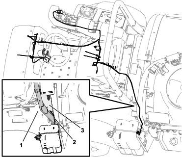
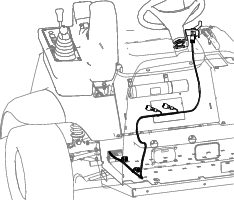
Route the wire harness from the foam-marker compressor behind the ROPS and under the guard plate (Figure 5).
-
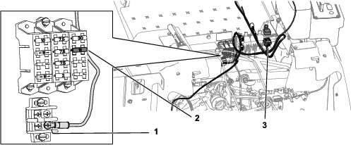
Connect the ground wire and relay switch and insert the 15 amp fuse into the fuse block (Figure 6).
-
Connect the blade connector to the socket connector of the fuse block.
-
Route the harness along the machine harness up to the control panel (Figure 7).
-
Connect the rocker switch to the harness (Figure 7).
-
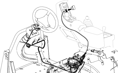
Route the harness under the panel on the floor plate and up to the steering column (Figure 8).
-
Attach the paddle switch bracket to the steering column with the 2 bolts (M6)
-
Assemble the switch into the bracket and press in the switch until it snaps securely into the opening.
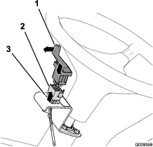
Note: Ensure that the paddle for the 3-position paddle switch (foam-control switch) is aligned outward.
Operation
Using the Controls
Foam paddle switch—activates the compressor, generating a flow of foam and air to the right or left boom section (Figure 10).
Foam on/off switch—activates the compressor, generating a flow of foam to both of the boom sections simultaneously (Figure 7).
Indicator markings—located on the side of the tank; they indicate the solution level in the tank.
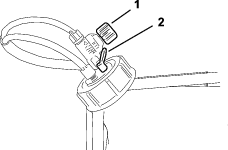
Foam regulator adjustment valve—controls the consistency of the foam solution. Adjusting the valve controls the amount of soap solution delivered to the foam nozzles. Increasing the flow results in larger, more frequent foam drops; decreasing the flow results in smaller, less frequent foam drops (Figure 11).
Note: A watery marker consistency may be helpful on windy days.
Pressure relief valve—pull the red tab on the tank cap outward to relieve pressure in the tank (Figure 11).
Filling the Tank and Adjusting the Foam Density
Important: Flush the system with clean water after each use, especially after using hard water. Do not apply lubricating oils, grease, or other petroleum products to the compressor motor assembly.
-
Ensure that both the left and right boom switches located on the console are in the Off position.
-
Pull out on the red pressure relief tab, and remove the black cap from the tank.
-
Pour the proper amount of water into the tank, and then add foam concentrate through the opening in the top of the tank according to the manufacturer’s instructions.
Important: Extreme pH levels (hardness or softness) of the water will affect the amount of foam concentrate needed.
-
Install the cap on the tank and tighten it by hand.
-
For the initial operation, open the foam density adjustment valve 1/8 to 1/4 turn (Figure 11).
-
Start operating the marking system and make a test pattern on the ground.
Note: When you first start the marking system, allow 1 to 2 minutes for the foam to flow through the line.
-
Adjust the foam density adjustment valve to obtain the desired consistency and spray as normal.
Note: If you leave the foam in the line for more than 2 hours, it may become watery. Before operating after a break of 2 or more hours, run the machine for 1 to 2 minutes to remove the excess water.
If the foam in the machine is very watery, do the following:
-
Close the foam density adjustment valve completely.
-
Operate for 2 minutes.
-
Wait 1 minute and then check the consistency of the foam.
-
Adjust the foam to achieve the desired consistency.
-