Installation
Note: The Foam Marker Kit is required to install this product. Contact your Authorized Toro Dealer for more information.
Preparing the Machine
Warning
Incorrect battery cable routing could damage the sprayer and cables, causing sparks. Sparks can cause the battery gasses to explode, resulting in personal injury.
-
Always disconnect the negative (black) battery cable before disconnecting the positive (red) cable.
-
Always reconnect the positive (red) battery cable before reconnecting the negative (black) cable.
Warning
Battery terminals or metal tools could short against metal sprayer components, causing sparks. Sparks can cause the battery gasses to explode, resulting in personal injury.
-
When removing or installing the battery, do not allow the battery terminals to touch any metal parts of the sprayer.
-
Do not allow metal tools to short between the battery terminals and metal parts of the sprayer.
-
Always keep the battery strap in place to protect and secure the battery.
-
Park the machine on a level surface.
-
Engage the parking brake.
-
Shut off the engine and remove the key.
-
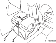
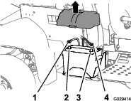
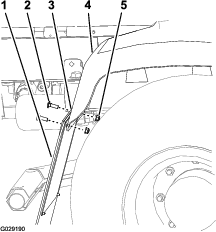
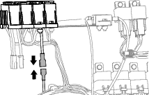
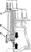
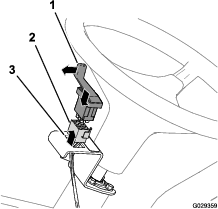
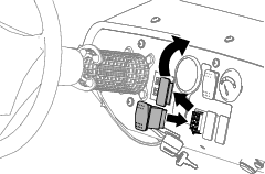
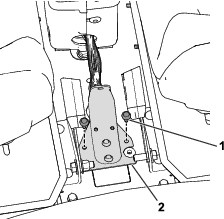
Remove the battery cover and disconnect the negative (black—ground) cable from the battery post (Figure 1 and Figure 2).
-
Disconnect the positive (red) cable from the battery post (Figure 2).
-
Tilt both seats forward and secure them by moving the prop rods into the detents at the end of the slots at the center-console base.
Assembling the Foam Marker
Parts needed for this procedure:
| Foam marker (sold separately) | 1 |
| Support bracket | 1 |
| Bolt (5/16 x 1 inch) | 4 |
| Flanged locknut (5/16 inch) | 4 |
| Washer (3/8 inch) | 4 |
Note: The foam marker is sold separately.
-
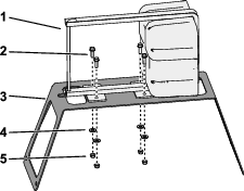
Align the foam marker tank and compressor to the mounting bracket as shown in Figure 3.
-
Secure the compressor to the bracket (Figure 3) using the 4 bolts (5/16 x 1 inch), 4 washers (3/8 inch), and 4 flanged locknuts (5/16 inch).
-
Install the foam marker tank onto the foam marker compressor; refer to the Installation Instructions for the foam marker kit.
Installing the Foam Marker and Support Bracket
Parts needed for this procedure:
| Flanged locknut (5/16 inch) | 4 |
| Carriage bolt (5/16 x 1-1/4 inch) | 4 |
| R-clamp | 1 |
| Bolt (3/8 inch) | 1 |
| Nut (3/8 inch) | 1 |
-
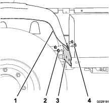
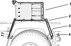
Remove the 2 carriage bolts and 2 flanged locknuts that secure the right, rear fender to the forward-fender bracket (Figure 4)
-
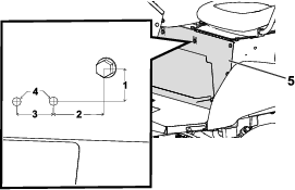
Remove the 2 carriage bolts and 2 flanged locknuts that secure the splash guard to the rear-fender mount and right, rear fender (Figure 5).
Note: Discard the old carriage bolts and nuts.
-
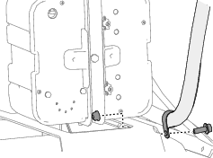
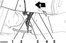
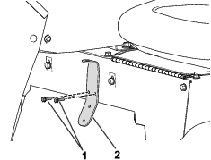
Align the holes in the front leg of the support bracket with the holes in the fender bracket and fender (Figure 6).
-
Secure the support bracket to the fender bracket and fender with 2 carriage bolts (5/16 x 1-1/4 inch) and 2 flanged locknuts (5/16 inch) as shown in Figure 6.
-
Align the holes in the rear leg of the support bracket with the holes in the splash guard, fender bracket, and fender (Figure 6).
-
Secure the support bracket to the splash guard, fender bracket, and fender with 2 carriage bolts (5/16 x 1-1/4 inch) and 2 flanged locknuts (5/16 inch) as shown in Figure 6.
-
If the machine has a rinse kit installed, secure the rinse-kit hose with the R-clamp as shown Figure 7.
Routing the Wire Harness
Parts needed for this procedure:
| Wire harness | 1 |
| Cable tie | 6 |
Routing the Compressor Branch of the Wire Harness
Routing the Engine-Compartment Branch of the Wire Harness
-
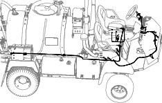
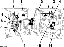
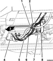
Route the wire harness for the finishing kit forward between the ROPS bar and the lower corner of the sprayer tank, along the wire harness of the machine, and below the air cleaner for the engine (Figure 10 and Figure 11).
-
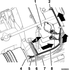
Route the 197 cm (77-1/2 inch)—engine-compartment branch of the wire harness (with the ring terminal, socket terminal, and 5-socket connector) up along the right side of the radiator, across the top of the radiator, and under the base of the center console (Figure 11).
-
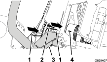
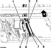
Route the 197 cm (77-1/2 inch)—engine-compartment branch of the wire harness down along the left side of the radiator and across the bottom of the electrical panel (Figure 12).
-
Secure the wire harness for the finishing kit to the wire harness for the machine with 2 cable ties as shown in Figure 12.
Routing the Dash-Panel Branch of the Wire Harness
-
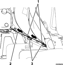
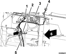
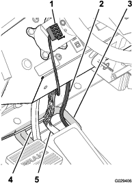
Route the 240 cm (94-1/2 inch)—dash-panel branch of the wire harness along the wire harness and steering hoses of the machine (below the radiator), through the R-clamp at the bottom of the radiator support, through the R-clamp at the ground-speed-control coil (Figure 13 and Figure 14).
-
Route the 240 cm (94-1/2 inch)—dash-panel branch of the wire harness to the R-clamp at the ground-speed-control coil (Figure 13 and Figure 14).
-
Route the 240 cm (94-1/2 inch)—dash-panel branch of the wire harness through the grommet at the opening in the forward bulkhead and inboard of the cable and hose hook (Figure 15).
-
Route the 8-socket connector at the end of the 240 cm (94-1/2 inch)—dash-panel branch across the dash panel and to the left of the steering column (Figure 16).
-
Adjacent to the cable and hose hook, secure the 240 cm (94-1/2 inch)—dash-panel branch to the wire harness for the machine with a cable tie (Figure 17).
Connecting the Wires
Parts needed for this procedure:
| Relay | 1 |
| Flange-head bolt (#10-24 x 1/2 inch) | 1 |
| Fuse (15 A) | 1 |
Connecting the Compressor Wire
-
At the end of the 236 cm (93 inch) branch of the wire harness, align the 4-socket connector of the wire harness for the finishing kit with the 4-pin connector of the wire harness from the compressor.
-
Insert the 4-pin connector into the 4-socket connector.
Note: Press the connectors together until the latch snaps securely.
Installing the Relay, Fuse, and Ground Wire
-
At the 197 cm (77-1/2 inch)—engine-compartment branch of the wire harness, align the relay with the 5-socket connect of the wire harness for the finishing kit (Figure 19).
-
Insert the pins of the relay into the sockets of the connector (Figure 19).
Note: Press the relay and connector together until the latch snaps securely.
-
Align the hole in the mounting tab of the relay with the hole in the wire panel (Figure 19).
-
Secure the relay to the panel (Figure 19) with the flange-head bolt (#10-24 x 1/2 inch).
-
Remove a screw from the ground-terminal block (Figure 19).
-
Secure the ring terminal of the wire harness for the finishing kit to the ground-terminal block with the screw.
Install the Fuse
-
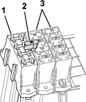
For a machine with the bladed-attachment connector at the fuse block for the machine, install the fuse into the fuse block (Figure 19).
Note: Ensure that the fuse is fully seated into the socket of the fuse block
-
For a machine with a bladed-attachment connector at the optional auxiliary-fuse block, perform the following:
-
Locate the fuse socket that is aligned with the wire of the blade connector.
-
Install the fuse into the socket that located in the auxiliary-fuse block (Figure 20).
Note: Ensure that the fuse is fully seated into the socket of the fuse block.
-
Connecting the Load Wire Connectors (Machine-Fuse Block)
Note: If you do not have a bladed-attachment connector at the fuse block for the machine available, you will need to install an auxiliary-fuse block.
-
For a machine with the bladed-attachment connector at the fuse block for the machine, connect the blade connector of the wire harness for the finishing kit to the socket connector of the fuse block for the machine (Figure 21).
-
Press the connectors together until the latch snaps securely.
Connecting the Load Wire Connectors (Optional Auxiliary-Fuse Block)
-
Connect the blade connector of the wire harness for the finishing kit to the socket connector of the auxiliary-fuse block (Figure 22).
Note: Press the connectors together until the latch snaps securely.
-
Connect the 2-pin connector for the auxiliary-feed wires of the fuse block for the machine to the 2-socket connector for the feed wires of the auxiliary-fuse block (Figure 23).
Note: Press the connectors together until the latch snaps securely.
-
Align the slots in the auxiliary-fuse block with the mounting flanges of the fuse block for the machine (Figure 23).
-
Assemble the fuse blocks together.
Installing the Switches
Parts needed for this procedure:
| Flange-head bolts (6 x 12 mm) | 2 |
| Mounting bracket (foam-control switch) | 1 |
| 3-position paddle switch (foam-control switch) | 1 |
| 2-position rocker switch (compressor on/off switch) | 1 |
Installing the Foam-Control Switch
-
Assemble the bracket to the column with the 2 flange-head bolts (6 x 12 mm) and torque the bolts to 972 to 1198 N-cm (86 to 106 in-lb).
-
Assemble the switch into the bracket and press in the switch until it snaps securely into the opening.
Note: Ensure that the paddle for the 3-position paddle switch (foam-control switch) is aligned outward.
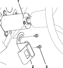
Installing the Compressor Switch
-
Remove the plug in the dash panel of the machine (Figure 26).
-
Align the 8-socket connector through the opening in the dash panel and connect the connector to the pins at the back of the 2-position rocker switch (compressor on/off switch).
-
Assemble the switch into the dash panel and press in the switch until the it snaps securely into the opening (Figure 26).
Installing the Valve Mount
Parts needed for this procedure:
| Valve mount | 1 |
| Hex-slotted screw (1/4–20 x 1/2 inch) | 2 |
| Flange-head screw (1/4–20 x 5/8 inch) | 2 |
| Flange nut (1/4 inch) | 2 |
Installing the Valve Mount to Model Year 2015 and Earlier Machines
Installing the Valve Mount to Model Year 2016 and Later Machines
-
Remove the harness base from the console by loosening and removing the bolts from the harness base (Figure 29).
Note: Retain and set aside the bolts.

-
Use 2 flange-head screws (1/4–20 x 5/8 inch) and 2 flange nuts (1/4 inch) secure the valve mount to the harness base (Figure 30).

-
Use the previously removed bolts to secure the harness base to the console (Figure 31).
Finishing the Installation of the Kit
-
Move the prop rod for the seats into the slots and tilt the seats down.
-
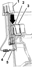
Connect the positive (red) cable to the positive (+) battery post and the negative (black) cable to the negative (–) battery post using the bolts and nuts. Slide the insulator boot over both battery posts (Figure 2).
-
Install the battery cover and secure it with the strap (Figure 1) that you removed in Preparing the Machine.
Operation
Using the Controls
-
COMPRESSOR ON/OFF switch—Use this switch to run the compressor for the foam marker system.
-
FOAM-CONTROL switch—Use this switch to control which boom from which foam flows.
-
Move the paddle down to apply foam from the left-boom section.
-
Move the paddle to the center position apply foam from the left- and right-boom sections.
-
Move the paddle up to apply foam from the right-boom section.
-
-
Indicator markings—The indicator markings are located at the side of the tank and indicate the solution level in the tank.
-
Foam-regulator valve—This valve controls the consistency of the foam solution. Adjusting the valve controls the amount of soap solution delivered to the foam nozzles. Increasing the flow results in larger, more frequent foam drops; decreasing the flow results in smaller, less frequent foam drops (Figure 32).
Note: A watery marker consistency may be helpful on windy days.
-
Pressure relief valve—Pull the red tab on the tank cap outward to relieve pressure in the tank (Figure 32).
Note: During compressor operation, the pressure-relief valve continuously opens/closes to maintain tank pressure; it is normal to see foam-marker solution and bubbles around the pressure-relief valve. Clean the pressure-relief valve periodically to maintain proper function of the valve.
