

Maintenance
Note: Determine the left and right sides of the machine from the normal operating position.For all maintenance procedures, park the machine on a level surface, shut off the engine, and remove the key.
Recommended Maintenance Schedule(s)
| Maintenance Service Interval | Maintenance Procedure |
|---|---|
| After the first 100 hours |
|
| Every 250 hours |
|
| Every 500 hours |
|
| Monthly |
|
| Every 2 years |
|
Warning
Working on the machine without the cab support bracket increases your risk of injury.
Before carrying out maintenance underneath the operator platform and cab, install the cab support bracket.
Caution
If you leave the key in the ignition switch, someone could accidently start the engine and seriously injure you or other bystanders.
Remove the key from the ignition before you do any maintenance.
Important: Maintenance or repairs on the heating system should be carried out by an authorized Toro distributor or a specialist in vehicle heating systems.
Important: All work on the refrigerant part of the air-conditioning system should be carried out by qualified personnel.
-
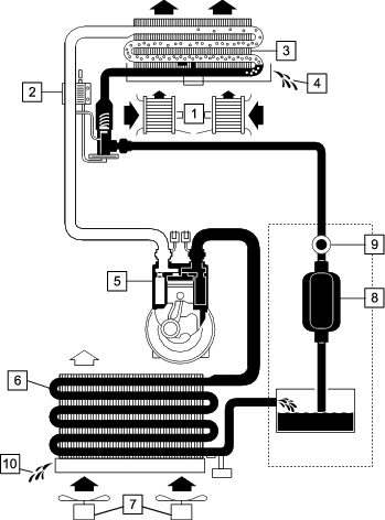
You can use the air-conditioning system for many months of the cutting season. Follow the regular prescribed maintenance to prolong the life of the system and ensure efficient operation. Failure to carry out the prescribed and documented maintenance could invalidate the warranty on the system and its components.
-
Even if the air-conditioning system is used infrequently, follow the maintenance schedule, as aging and refrigerant loss can occur with time.
-
Low levels of refrigerant can reduce the efficiency of the air-conditioning unit.
-
Extremely low levels can cause the low-pressure switch to shut down the system.
-
To check the refrigerant level, there is an integrated sight glass in the collecting tank. After filling, run the system for 5 minutes to allow all air bubbles to be purged from the system. Check the level after this period and top up is necessary. The occasional air bubble can be accepted.
Important: Do not spill compressor oil on the vehicle surface. It can cause discoloration of vehicle paint and deterioration of acrylic or ABS plastic components.
-
When attaching the refrigerant hoses, oil the sealing rings with refrigerant oil.
-
After removal of refrigerant hoses from the air-conditioner system, always replace the O-rings with new ones specified for refrigerant 134A.
-
When tightening or loosening fittings, always use 2 wrenches to prevent the tubes from twisting.
Preparing for Maintenance
Preform the following steps each time you maintain the machine.
-
Move the machine to a level surface.
-
Engage the parking brake and lower the cutting units.
-
Shut off the engine and remove the key.
-
Wait for all moving parts to stop.
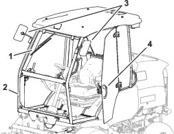
Tilting the Cab
You can tilt the cab for access under the operator platform for cleaning and maintenance.
The cab and the operator platform tilt together as a single unit. The angle of tilt is less than that of a platform without a cab. This is to ensure that, owing to the weight and position of the tilted cab, the machine has sufficient stability when you tilt the cab.
Tilting the Cab Forward
-
Ensure that the rear widow is shut and locked.
-
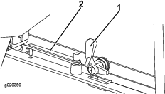
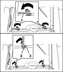
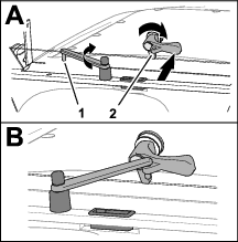
At the cross beam near the back of the cab, remove the 2 hairpins that secure the latch pins to the cab supports.
-
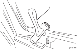
Rotate the latch-pin handles so that they point upward (Figure 21).
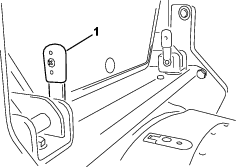
-
Slide the latch pins inboard, and remove them from the cab supports.
Note: If the latch pins are difficult to remove, move the handles of the latch pins back and forth to help free the pins from the flange holes and beam bracket holes.
-
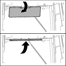
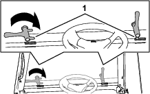
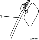
At either sides of the cab, slowly lift the grab handle on rear corner post until the cab is fully raised.
Note: Gas spring lift cylinders help you raise the cab, and stop it from tilting further when it is fully raised.
-
Remove the cab-support bracket from the storage compartment.
-
At either side of the machine, align the hole in the cab-support bracket with the holes in the cross-beam bracket, and secure the support bracket to the beam bracket with a latch pin and hairpin.
-
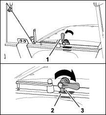
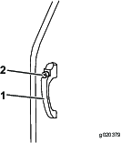
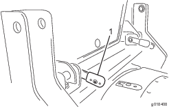
Rotate the cab support bracket toward the cab so that it aligns between the cab-frame flanges, and rests against the back of the cab frame (Figure 23).
-
Insert the other latch pin through the holes in the cab-frame flange, and secure the latch pin to the flanges with the hairpin (Figure 23).
Lowering the Cab
-
Remove the 2 hairpins and latch pins that secure the cab support bracket to the cab and the cross-beam bracket, and remove the cab support.
-
At either sides of the cab, slowly pull down the grab handle on the rear corner post until the cab is fully lowered.
-
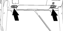
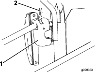
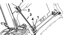
Align the holes in the cab-frame flange and the holes in the cross-beam bracket (Figure 24).
-
Insert the 2 latch pins (Figure 24) through the holes in the cab-frame flanges and cross-beam brackets.
Note: If the latch pins are difficult to insert, move the handles of the latch pins back and forth to help align the pins to the flange holes and beam bracket holes.
-
Rotate the latch-pin handles horizontal (Figure 25), and secure the latch pins with the 2 hairpins.
-
Stow the cab-support bracket in the storage compartment.
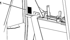
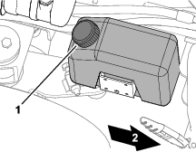
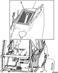
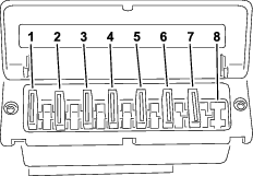
Locating the Fuses
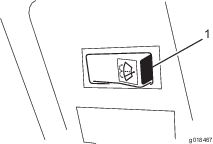
The cab fuses are located in the fuse box in the cab headliner (Figure 26).
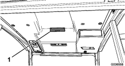
Note: The fuse identification numbers are molded into the fuse-box cover.
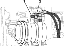
Checking the Air-Conditioner Compressor Clutch
| Maintenance Service Interval | Maintenance Procedure |
|---|---|
| Every 250 hours |
|
-
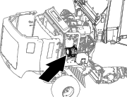
Unlatch and open the hood (Figure 36).
-
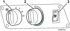
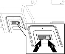
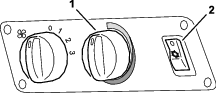
Have another person sit in the operator’s seat, rotate the temperature control to the cold position, and press the air-conditioner switch to the ON and OFF positions (Figure 29).
-
At the back of the machine, listen for the compressor clutch (Figure 30) engaging and disengaging (clicking).
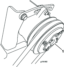
-
Press the air-conditioner switch (Figure 29) to the OFF position.
Important: To prevent the battery discharge, ensure the air-conditioner switch is in the OFF position.
Removing the Roof
-
Remove the 4 bolts, 4 washers, and 4 seals that secure the roof to the cab (Figure 31).
Note: Do not remove the 8 bolts around the fans.
Important: The fans are mounted to the roof.
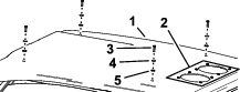
-
Disconnect the wire-harness connectors at each of the fans.
-
Carefully remove the roof from the cab.
Installing the Roof
-
Position the roof onto the frame of the cab.
-
Connect the wire-harness connectors at each of the fans.
-
Align the holes in the roof with the clip nuts of the cab frame.
-
Assemble the roof to the cab with the 4 bolts, 4 washers, and 4 seals (Figure 31) that you removed in step 1.
Checking the Refrigerant Level
| Maintenance Service Interval | Maintenance Procedure |
|---|---|
| Monthly |
|
Check the refrigerant to assure it is at the correct level for air-conditioner operation.
-
Remove the hardware securing the roof; refer to Removing the Roof.
Note: Do not remove the roof.
-
Ensure that the parking brake is engaged, start the engine, rotate the temperature control to the cold position, and press the air-conditioner switch to the ON positions (Figure 32).
-
Idle the engine for 5 minutes to allow the air-conditioning system to purge air bubbles from the refrigerant.
-
Move the roof enough to access the collecting-filter tank (Figure 33).
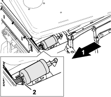
-
At the roof, observe the refrigerant-level sight gauge of the collecting-filter tank (Figure 33). If there are more that the occasional bubble seen through the sight glass, contact your authorized Toro distributor for service.
Note: If you see an occasional air bubble, the refrigerant-level is acceptable. As the refrigerant level lowers, you will see more air bubbles passing through the sight glass. Low levels of refrigerant reduce the air-condition effectiveness.
Important: An extremely low refrigerant level causes the low-pressure switch to shut down the air-conditioner.
-
Press the air-conditioner switch (Figure 32) to the OFF position and shut off the engine.
Important: To prevent the battery discharge, ensure the air-conditioner switch is in the OFF position.
Inspecting and Cleaning the Condenser
| Maintenance Service Interval | Maintenance Procedure |
|---|---|
| Monthly |
|
-
Remove the roof from the cab; refer to Removing the Roof.
-
Examine the fins of the condenser and evaporator for accumulating dust and debris.
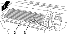
-
If needed, clean the condenser and evaporator fins with compressed air in the opposite direction of the normal air flow. If there is any buildup of greasy deposits, clean it with a non-abrasive soap solution.
-
Install the cab roof; refer to Installing the Roof.
Checking the Drain Tubes
| Maintenance Service Interval | Maintenance Procedure |
|---|---|
| Every 250 hours |
|
The water drains are clear plastic tubes that connect to the blower evaporator in the cab roof. The drain tubes route down both front cab pillars, and drain water from the evaporator.
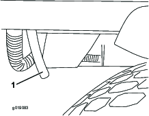
-
Check the drain tubes for blockages.
-
If the tube is blocked, use a flexible cleaning tool, such as a pipe cleaner. If needed, disconnect the tube from the condenser-drain fitting, and blow out the tube with compressed air.
Checking the Compressor-Fan Belt
| Maintenance Service Interval | Maintenance Procedure |
|---|---|
| Every 500 hours |
|
-
Unlatch and open the hood (Figure 36).
-
Check belt tension by applying 40 N (9 lb) of force on the belt (Figure 37), midway between the engine pulley and the compressor pulley.
Note: The belt is properly tensioned if the belt deflects 10 mm (3/8 inch).
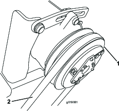
-
If belt deflection is greater than or less that 10 mm (3/8 inch), loosen the upper and lower compressor-mounting bolts.
-
Rotate the compressor to increase or decrease the belt tension, and tighten the bolts.
-
Repeat step 2 to ensure that the belt tension is correct.
-
Close the hood, and latch it.
Checking the Refrigerant Pressure
When using the air-conditioning system the operating pressure is different on the suction (low pressure) side and the pressure (high pressure) side of the compressor; refer to Figure 38.
This pressure difference is influenced by the speed of the compressor, the inside temperature of the vehicle, the outside air temperature and the relative air humidity.
Pressures that differ from those in the table below indicate a possible fault in the system.
To check the pressures, set the compressor speed to 2000 rpm with an air temperature between 20 and 40 degrees C (68 and 104 degrees F). Operate the blower at position 3 (fastest speed setting).
|
Outside Temperature |
Low-Pressure Side |
High-Pressure Side |
|---|---|---|
|
20° C (68° F) |
1.7 to 2.1 bar |
10 to 14 bar |
|
(24.7 to 30.5 psi) |
(145 to 203 psi) |
|
|
25° C (77° F) |
1.8 to 2.2 bar |
12 to 16 bar |
|
(26.1 to 31.9 psi) |
(174 to 232 psi) |
|
|
30° C (86° F) |
1.9 to 2.3 bar |
14 to 18 bar |
|
(27.6 to 33.4 psi) |
(203 to 261 psi) |
Troubleshooting the Pressure Readings
During the compression test, deviations from the values in the table may be measured. Locating the cause can determine whether a part requires repair or replacement.
The following is a short list of some pressure deviation that may be measured and some possible causes.
-
Pressure on high-pressure manometer too high
-
The air volume in the condenser is too small.
-
Refrigerant quantity is too high
-
The dryer/filter is blocked.
-
-
Pressure on high-pressure manometer is too low
-
The refrigerant quantity is too low (check the sight glass).
-
The compressor speed is too low (check the drive belt for slip/tension).
-
There is a fault with the compressor.
-
-
Pressure on low-pressure manometer too high
-
The expansion valve is incorrect.
-
The compressor speed is too low (check the drive belt for slip/tension).
-
There is a fault with the compressor.
-
-
Pressure on low-pressure manometer too low
-
There is restriction in the suction or pressure hoses.
-
The expansion valve is incorrect.
-
The refrigerant quantity is too low (examine the sediment bowl).
-
The air volume in the evaporator is too small.
Have a qualified person examine and repair all deviations in pressure from the values in the table.
-
Important: Do not allow refrigerant to discharge into the atmosphere. Before opening or disconnecting parts from the refrigerant circuit, empty the refrigerant into a specified recycling bottle, and dispose of it correctly.
Always use genuine Toro spare parts when repairing or servicing the air-conditioning system.
Washing the Machine and Cab
When washing the machine and the cab, do not direct water into the roof area.
Important: Do not use brackish or reclaimed water to clean the machine.