Maintenance
Recommended Maintenance Schedule(s)
| Maintenance Service Interval | Maintenance Procedure |
|---|---|
| After the first 250 hours |
|
Cleaning
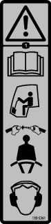
Caution
If you leave the key in the switch, someone could accidently start the engine and seriously injure you or other bystanders.
Remove the key from the switch before you do any maintenance.
Cleaning the Cab
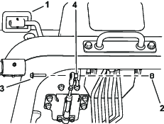
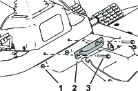
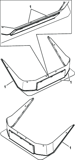
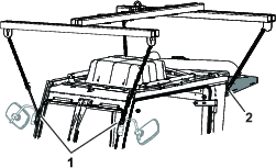
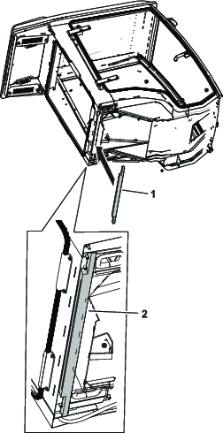
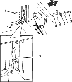
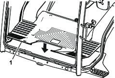
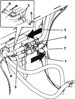
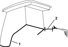
Important: Use care around the cab seals (Figure 32). If you are using a pressure washer, keep the washer wand at least 0.6 m (2 ft) away from the machine. Do not use the pressure washer directly on the cab seals, glass seals, and under the rear overhang.
Cleaning the Air Filters
| Maintenance Service Interval | Maintenance Procedure |
|---|---|
| After the first 250 hours |
|
-
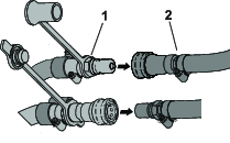
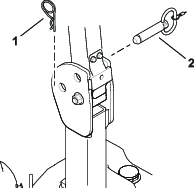
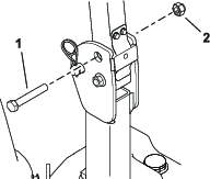
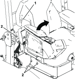
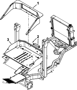
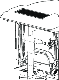
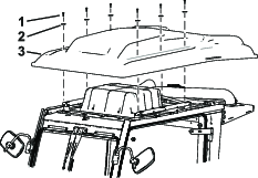
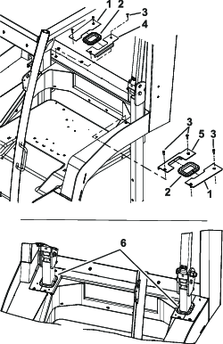
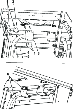
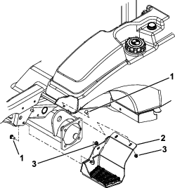
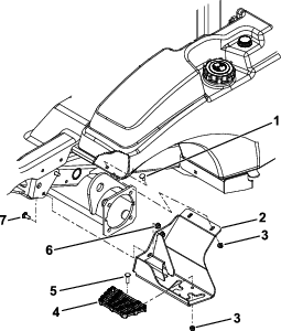
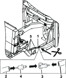
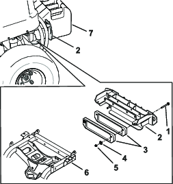
Remove the thumb screws and the grates from the rear cab air filters (Figure 33).
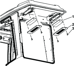
-
Clean the filters by blowing clean, oil free, compressed air through them.
Important: Replace any damaged filters.
-
Install the filters and grate, securing them with the thumb screws.