


Maintenance
Note: Determine the left and right sides of the machine from the normal operating position.
Maintenance Safety
-
Park machine on level ground. Disengage the spray or close the spreader gate, set the parking brake, stop engine and remove key or disconnect spark plug wire. Wait for all moving parts to stop before leaving the operator’s position. Allow the machine to cool before servicing, adjusting, fueling, unclogging, cleaning, or storing.
-
If you leave the key in the switch, someone could accidently start the engine and seriously injure you or other bystanders. Remove the key from the switch before you perform any maintenance.
-
Never allow untrained personnel to service machine.
-
Disconnect battery or remove spark plug wire before making any repairs. Disconnect the negative terminal first and the positive last. Reconnect positive first and negative last.
-
Relieve the spray pressure from the system before servicing.
-
Empty the tank and/or hopper before tilting the machine for maintenance and before storing.
-
Keep all guards, shields, switches, and all safety devices in place and in proper working condition. Frequently check for worn or deteriorating components and replace them with genuine Toro parts when necessary.
Warning
Removal or modification of original equipment, parts and/or accessories may alter the warranty, controllability, and safety of the machine. Unauthorized modifications to the original equipment or failure to use original Toro parts could lead to serious injury or death. Unauthorized changes to the machine, engine, fuel or venting system, may violate applicable safety standards such as: ANSI, OSHA and NFPA and/or government regulations such as EPA and CARB.
Warning
Hydraulic fluid escaping under pressure can penetrate skin and cause injury. Fluid accidentally injected into the skin must be surgically removed within a few hours by a doctor familiar with this form of injury or gangrene may result.
-
If equipped, make sure all hydraulic fluid hoses and lines are in good condition and all hydraulic connections and fittings are tight before applying pressure to hydraulic system.
-
Keep body and hands away from pinhole leaks or nozzles that eject high pressure hydraulic fluid.
-
Use cardboard or paper, not your hands, to find hydraulic leaks.
-
Safely relieve all pressure in the hydraulic system by placing the motion control levers in neutral and shutting off the engine before performing any work on the hydraulic system.
-
-
Do not rely solely on mechanical or hydraulic jacks for support. Use adequate jack stands.
-
Carefully release pressure from components with stored energy.
-
Keep your hands and feet away from moving parts or hot surfaces. If possible, do not make adjustments with the engine running.
-
Keep all parts in good working condition and all hardware tightened.
Recommended Maintenance Schedule(s)
| Maintenance Service Interval | Maintenance Procedure |
|---|---|
| After the first 5 hours |
|
| After the first 100 hours |
|
| Before each use or daily |
|
| Every 40 hours |
|
| Every 50 hours |
|
| Every 80 hours |
|
| Every 100 hours |
|
| Monthly |
|
Notation for Areas of Concern
| Inspection performed by: | ||
| Item | Date | Information |
| 1 | ||
| 2 | ||
| 3 | ||
| 4 | ||
| 5 | ||
| 6 | ||
| 7 | ||
| 8 | ||
Important: Refer to your engine owner’s manual for additional maintenance procedures.
Lubrication
Lubricate Grease Fittings
| Maintenance Service Interval | Maintenance Procedure |
|---|---|
| Every 100 hours |
|
Note: See chart for service intervals.
-
Stop engine, wait for all moving parts to stop, and remove key. Engage parking brake.
-
Lubricate fittings with NLGI grade #2 multi-purpose gun grease.
Refer to the maintenance chart for fitting locations and lubrication schedule.
Lubrication Chart
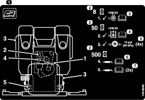
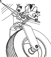
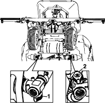
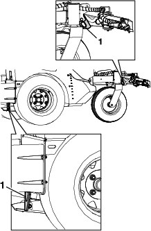
Fitting Locations Initial Pumps Number of Places Service Interval 1. Front Caster Pivots *0 2 Yearly 2. Idler Pivot 1 1 Yearly 
*See step 3 for special lubrication instructions on the caster pivots.
-
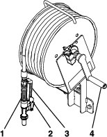
Lubricate caster pivots once a year. Remove hex plug and cap. Thread grease zerk in hole and pump with grease until it oozes out around top bearing. Remove grease zerk and thread plug back in. Place cap back on.
Engine Maintenance
Service Air Cleaner
| Maintenance Service Interval | Maintenance Procedure |
|---|---|
| Before each use or daily |
|
| Every 100 hours |
|
-
Stop engine, wait for all moving parts to stop, and remove key. Engage parking brake.
-
See the engine owner’s manual for maintenance instructions.
Check Engine Oil Level
| Maintenance Service Interval | Maintenance Procedure |
|---|---|
| Before each use or daily |
|
-
Stop engine and wait for all moving parts to stop. Make sure unit is on a level surface.
-
Check with engine cold.
-
Clean area around dipstick. Remove dipstick and wipe oil off. Reinsert the dipstick according to the engine manufacturer's recommendations. Remove the dipstick and read the oil level.
-
If the oil level is low, wipe off the area around the oil fill cap, remove cap and fill to the FULL mark on the dipstick. Refer to the engine owner’s manual for an appropriate API rating and viscosity. Do not overfill.
Important: Do not operate the engine with the oil level below the LOW (or ADD) mark on the dipstick, or over the FULL mark.
Change Engine Oil
| Maintenance Service Interval | Maintenance Procedure |
|---|---|
| After the first 5 hours |
|
| Every 100 hours |
|
-
Stop engine, wait for all moving parts to stop, and remove key. Engage parking brake.
-
Flip the hopper forward.
-
Drain oil while engine is warm from operation.
-
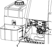
Remove dip stick. The oil drain plug is located on the left side of the engine.
Place pan under machine to catch oil. Remove drain oil plug to open and allow oil to drain and reinstall plug when complete.
-
Replace the oil filter every other oil change. Clean around oil filter and unscrew filter to remove. Before reinstalling new filter, apply a thin coating of engine oil on the surface of the rubber seal. Turn filter clockwise until rubber seal contacts the filter adapter then tighten filter an additional 1/2 to 3/4 turn.
-
Clean around oil fill cap and remove cap. Fill to specified capacity and replace cap.
-
Use oil recommended in the Check Engine Oil Level section. Do not overfill. Start the engine and check for leaks. Stop engine and recheck oil level.
-
Wipe up any spilled oil from engine deck mounting surfaces.
-
Lower and latch the hopper into operating position.
Fuel System Maintenance
Check Fuel Filter and Tank
| Maintenance Service Interval | Maintenance Procedure |
|---|---|
| Before each use or daily |
|
-
Stop engine, wait for all moving parts to stop, and remove key. Engage parking brake.
-
Check the fuel filter and tank for leaks. See engine owner’s manual.
Electrical System Maintenance
Check Battery Charge
| Maintenance Service Interval | Maintenance Procedure |
|---|---|
| Monthly |
|
Allowing batteries to stand for an extended period of time without recharging them will result in reduced performance and service life. To preserve optimum battery performance and life, recharge batteries in storage when the open circuit voltage drops to 12.4 V.
Note: To prevent damage due to freezing, battery should be fully charged before putting away for winter storage.
Charge batteries in an open well ventilated area, away from spark and flames. Unplug charger before connecting or disconnecting from battery. Wear protective clothing and use insulated tools.
Danger
Charging or jump starting the battery may produce explosive gases. Battery gases can explode causing serious injury.
-
Keep sparks, flames, or cigarettes away from battery.
-
Ventilate when charging or using battery in an enclosed space.
-
Make sure venting path of battery is always open once battery is filled with acid.
-
Always shield eyes and face from battery.
Danger
Battery electrolyte contains sulfuric acid, which is poisonous and can cause severe burns. Swallowing electrolyte can be fatal or if it touches skin can cause severe burns.
-
Wear safety glasses to shield eyes, and rubber gloves to protect skin and clothing when handling electrolyte.
-
Do not swallow electrolyte.
-
In the event of an accident, flush with water and call a doctor immediately.
Caution
If the ignition is in the ON position there is potential for sparks and engagement of components. Sparks could cause an explosion or moving parts could accidentally engage causing personal injury.
Be sure ignition switch is in the OFF position before charging the battery.
-
Check the voltage of the battery with a digital voltmeter or with the message display. If the voltage is less than 12.4 V, the battery may need to be charged.
Important: In order to prevent damage to the battery, use an automatic 12 volt smart charger approved for use with AGM type batteries with an output of 3.5 amps or less. Toro recommends the use of battery charger P/N 135-7024. Make sure the negative battery cable is disconnected before charging and that the charger is set to the correct mode for 12 V AGM batteries.
-
Connect the negative battery cable.
Note: If the positive cable is also disconnected, connect the positive (red) cable to the positive battery terminal first, then the negative (black) cable to the negative battery terminal. Slip insulator boot over the positive terminal.
Note: If time does not permit charging the battery, or if charging equipment is not available, connect the negative battery cables and run the vehicle continuously for 20 to 30 minutes to sufficiently charge the battery.
Recommended Jump Starting Procedure
-
Check the weak battery for terminal corrosion (white, green, or blue “snow”), it must be cleaned off prior to jump starting. Clean and tighten connections as necessary.
Caution
Corrosion or loose connections can cause unwanted electrical voltage spikes at anytime during the jump starting procedure.
Do not attempt to jump start with loose or corroded battery terminals or damage to the engine may occur.
Danger
Jump starting a weak battery that is cracked, frozen, has low electrolyte level, or an open/shorted battery cell, can cause an explosion resulting in serious personal injury.
Do not jump start a weak battery if these conditions exist.
-
Make sure the booster is a good and fully charged lead acid battery at 12.6 V or greater. Use properly sized jumper cables (4 to 6 AWG) with short lengths to reduce voltage drop between systems. Make sure the cables are color coded or labeled for the correct polarity.
Caution
Connecting the jumper cables incorrectly (wrong polarity) can immediately damage the electrical system.
Be certain of battery terminal polarity and jumper cable polarity when hooking up batteries.
Note: The following instructions are adapted from the SAE J1494 Rev. Dec. 2001 – Battery Booster Cables – Surface Vehicle Recommended Practice (SAE – Society of Automotive Engineers).
Warning
Batteries contain acid and produce explosive gases.
-
Shield the eyes and face from the batteries at all times.
-
Do not lean over the batteries.
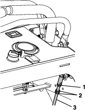
Note: Be sure the vent caps are tight and level. Place a damp cloth, if available, over any vent caps on both batteries. Be sure the vehicles do not touch and that both electrical systems are off and at the same rated system voltage. These instructions are for negative ground systems only.
-
-
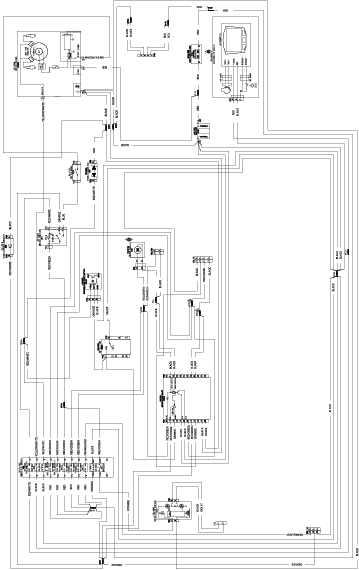
Connect the positive (+) cable to the positive (+) terminal of the discharged battery that is wired to the starter or solenoid as shown in .
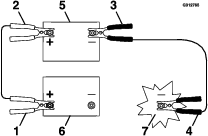
-
Connect the other end of the positive cable to the positive terminal of the booster battery.
-
Connect the black negative (–) cable to the other terminal (negative) of the booster battery.
-
Make the final connection on the engine block of the stalled vehicle (not to the negative post) away from the battery. Stand back.
-
Start the vehicle and remove the cables in the reverse order of connection (the engine block (black) connection is the first to disconnect).
Drive System Maintenance
Check Tire Pressures
| Maintenance Service Interval | Maintenance Procedure |
|---|---|
| Every 50 hours |
|
-
Stop engine, wait for all moving parts to stop, and remove key. Engage the parking brake.
-
Check the tire pressure in the drive tires.
-
Inflate all tires to 13 psi (90 kPa).
Wheel Mount Screw Torque Specification
| Maintenance Service Interval | Maintenance Procedure |
|---|---|
| After the first 100 hours |
|
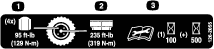
Torque the lug nuts on the wheel hub to 129 N•m (95 ft-lb).
Belt Maintenance
Check Condition of Belt
| Maintenance Service Interval | Maintenance Procedure |
|---|---|
| Every 40 hours |
|
-
Stop engine, wait for all moving parts to stop, and remove key. Engage parking brake.
-
Check the belt condition and tension.
Controls System Maintenance
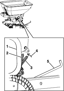
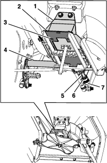
Adjusting the Parking Brake
If the parking brake does not hold securely, an adjustment is required.
-
Park the machine on a level surface and engage the brake.
-
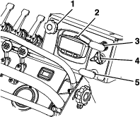
Shut off engine and wait for all moving parts to stop. Remove and retain the rear cover panel in front of the Operator’s platform.
-
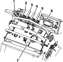
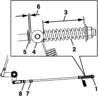
With the park brake engaged, the compression spring on both sides should measure 51 mm (2 inches). The gap between the trunnion and the shoulder should measure 3-6 mm (0.12-0.24 inch) on the lower brake linkages.
-
To adjust the spring length, turn the nut clockwise to shorten the spring. Cycle the park brake lever off and on and re-measure the spring length and check the gap.
-
To adjust the gap, loosen the jam nuts on the lower brake linkage against the clevis yokes. Using the two jam nuts, tighten together and rotate the linkage in the appropriate direction to either increase or decrease the gap. Cycle the park brake lever off and on and re-measure gap and spring length.
-
Engage the park brake and check. If more adjustment are needed, repeat steps 5 and 6.
-
Retighten the jam nuts.
-
Install the left rear hydro cover.
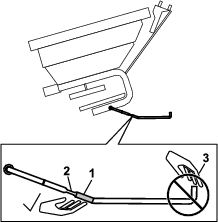
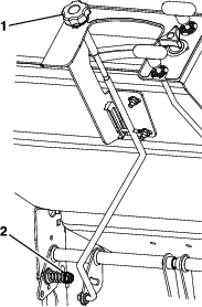
Motion Control Linkage Adjustment
-
Park the machine on a level surface.
-
Stop engine, wait for all moving parts to stop, and remove key. Engage parking brake.
-
Loosen the two knobs that secure the front reference/speed control bar and push it all the way forward. Slightly tighten the knobs.
-
With the motion control levers in the neutral position, the gap between the front reference/speed control bar should measure 95 mm (3.75 inches).
-
If an adjustment is needed, remove the knee pad.
-
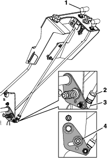
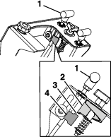
Loosen the upper jam nut at the base of the ball joint as shown in Figure 45. Adjust the control rod length by turning the two jam nuts. To increase the gap, turn the control rod counterclockwise. To decrease the gap, turn the control rod clockwise.
-
Retighten the jam nuts on the control rod.
-
Replace the knee pad.
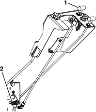
Motion Control Tracking Adjustment
If the machine travels or pulls to one side when the motion control levers are in the full forward position, adjust the tracking.
-
Park the machine on a level surface.
-
Stop engine, wait for all moving parts to stop, and remove key. Engage parking brake.
-
Make sure there is a 95 mm (3.75 inches) gap between the motion control levers and the front reference/speed control bar. Refer to Motion Control Linkage Adjustment.
-
Remove the knee pad.
-
Loosen the top jam nut at the upper end of the ball joint on the lever that needs to be adjusted (Figure 45).
-
To increase the speed, turn the control rod counterclockwise in quarter turn increments. To decrease the speed, turn the control linkage clockwise in quarter turn increments.
-
Retighten the jam nuts on the control rod.
-
Drive the machine and check the full forward tracking.
-
Replace the knee pad.
-
Repeat steps 5 through 8 until desired tracking is obtained.
Hydraulic System Maintenance
Check Hydraulic Oil and Tank Level
| Maintenance Service Interval | Maintenance Procedure |
|---|---|
| Every 40 hours |
|
-
Stop engine and wait for all moving parts to stop, and remove key. Engage parking brake.
-
Wait until the machine cools before checking the hydraulic oil.
-
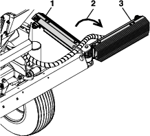
With the hopper empty, tip the hopper forward.
-
Clean area around oil overflow tank and remove cap. Oil level should be at the FULL COLD line; if not, add hydraulic oil. Replace tank cap and tighten until snug. Do not overtighten.
Change Hydraulic System Filter and Fluid
| Maintenance Service Interval | Maintenance Procedure |
|---|---|
| After the first 100 hours |
|
-
Stop engine, wait for all moving parts to stop, and remove key. Engage parking brake.
-
Carefully clean area around the filter. It is important that no dirt or contamination enter hydraulic system.
-
Place a catch pan under each hydro filter.
-
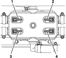
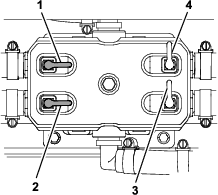
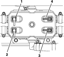
Remove and retain the oil filter covers on each of the transaxles. Remove and discard the O-ring from the covers.
-
Allow the oil to drain. Remove and discard the filters from the transaxle housings.
Install a new O-ring onto the filter cover and reinstall the cover. Torque to 51-65 N•m (450-580 in-lb).
-
Remove the top oil fill vent port plug and fill until it reaches the oil fill vent port. Reinstall the vent port plug and continue to fill as stated in Check Hydraulic Oil and Tank Level.
Hydro Oil Service Interval Toro Hypr-Oil 500 After first 100 hours *Every 400 hours thereafter Mobil 1 15W-50 After first 100 hours *Every 250 hours thereafter *May need more often under severe conditions.
-
Remove the catch pan and properly dispose of hydro oil and filter according to local codes.
Note: Do not change hydraulic system oil (except for what can be drained when changing filter), unless it is felt the oil has been contaminated or been extremely hot.Changing oil unnecessarily could damage hydraulic system by introducing contaminates into the system.
Hydraulic System Air Purge
Air must be purged from the hydraulic system when any hydraulic components, including oil filter are removed.
-
Stop engine and wait for all moving parts to stop. Raise the rear of the machine up onto jack stands high enough to raise the drive wheels off the ground.
-
Check oil level as described in Check Hydraulic Oil and Tank Level.
-
Start engine and move throttle control ahead to full throttle position. Move the speed control lever to the middle speed position and place the drive levers in the DRIVE position.
-
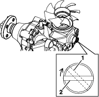
Open the drive wheel release on each pump.
-
With the machine running, slowly stroke the drive levers from forward to reverse several times. Then, retighten the drive wheel release valves. Slowly stroke the drive levers from forward to reverse several times.
-
If either drive wheel still does not rotate, stop and repeat steps 4 and 5 above for the respective pump. If wheels rotate slowly, the system may prime after additional running. Check oil level as described in Check Hydraulic Oil and Tank Level.
-
Allow the machine to run several minutes after the charge pumps are “primed” with drive system in the full speed position. Check oil level as described in Check Hydraulic Oil and Tank Level.
-
Check hydro drive linkage adjustment.
Maintaining the Chassis
Check for Loose Hardware
| Maintenance Service Interval | Maintenance Procedure |
|---|---|
| Before each use or daily |
|
-
Stop engine, wait for all moving parts to stop, and remove key. Engage parking brake.
-
Visually inspect machine for any loose hardware or any other possible problem. Tighten hardware or correct the problem before operating.
Maintaining the Sprayer and Spreader Systems
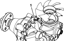
Check Spreader System
| Maintenance Service Interval | Maintenance Procedure |
|---|---|
| Every 50 hours |
|
Clean the bottom of the hopper with a wire brush and clean off any fertilizer if needed.
Change out the hopper bottom bushing or the impeller if needed.
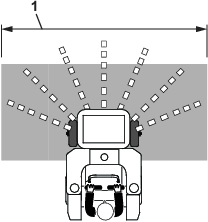
Check Sprayer System
| Maintenance Service Interval | Maintenance Procedure |
|---|---|
| Every 50 hours |
|
-
Stop engine, wait for all moving parts to stop, and remove key. Engage parking brake.
-
Check all hoses, nozzles, and fittings for leaks.
-
Check nozzle strainers and in-line strainers.
-
Replace as needed.
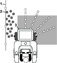
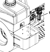
Check In-line Filter
Periodically check the in-line filter for any debris in the screen. If debris is present, this can create erratic pressure spikes and/or not allow the proper flow through system. After clearing any debris, ensure that gasket remains intact and tighten in-line filter cap (if not installed properly, this will allow air to get in the system and system will lose or not create pressure).

Cleaning
Cleaning and Storing Safety
-
Park machine on level ground, disengage drives, set parking brake, stop engine, and remove key. Wait for all moving parts to stop before leaving the operator’s position. Allow the machine to cool before servicing, adjusting, fueling, unclogging, cleaning, or storing.
-
Clean grass and debris from the muffler, drives, and engine compartment to prevent fires.
-
Allow the machine to cool before storing the machine in any enclosure. Do not store the machine or fuel container, or refuel, where there is an open flame, spark, or pilot light such as on a water heater or other appliance.
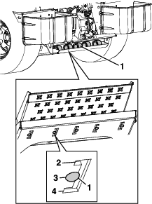
Clean Engine and Exhaust System Area
| Maintenance Service Interval | Maintenance Procedure |
|---|---|
| Before each use or daily |
|
Caution
Excessive debris around engine cooling air intake and exhaust system area can cause engine, exhaust area, and hydraulic system to overheat which can create a fire hazard.
Clean all debris from engine and exhaust system area.
-
Stop engine, wait for all moving parts to stop, and remove key. Engage parking brake.
-
Clean all debris from rotating engine air intake screen, around engine shrouding, and exhaust system area.
-
Wipe up any excessive grease or oil around the engine and exhaust system area.
-
Clean muffler heat shields of all debris, dirt, and oil.
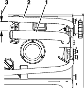
Remove Engine Shrouds and Clean Cooling Fins
| Maintenance Service Interval | Maintenance Procedure |
|---|---|
| Every 80 hours |
|
-
Stop engine, wait for all moving parts to stop, and remove key. Engage parking brake.
-
Remove cooling shrouds from engine and clean cooling fins. Also clean dust, dirt, and oil from external surfaces of engine which can cause improper cooling.
-
Make sure cooling shrouds are properly reinstalled. Operating the engine without cooling shrouds will cause engine damage due to overheating.
Clean Debris From Machine
| Maintenance Service Interval | Maintenance Procedure |
|---|---|
| Before each use or daily |
|
-
Stop engine, wait for all moving parts to stop, and remove key. Engage parking brake.
-
Clean off any oil, debris, or build-up on the machine, especially the nozzles, tank opening, impeller, spray wand and its holder, around engine and exhaust area.
Important: You can wash the machine with mild detergent and water. Do not pressure wash the machine. Avoid excessive use of water, especially near the control panel, under the cushion, around the engine, hydraulic pumps, motors, and drive axle seals.
Waste Disposal
Chemical Disposal
Improper chemical disposal can pollute the environment and cause health issues.
Follow the disposal directions on the chemical manufacturer’s label. Dispose of chemicals and containers in accordance to local/state/federal laws.
Motor Oil Disposal
Engine oil and hydraulic oil are both pollutants to the environment. Dispose of used oil at a certified recycling center or according to your state and local regulations.
Battery Disposal
Danger
Battery electrolyte contains sulfuric acid, which is poisonous and can cause severe burns. Swallowing electrolyte can be fatal or if it touches skin can cause severe burns.
-
Wear safety glasses to shield eyes, and rubber gloves to protect skin and clothing when handling electrolyte.
-
Do not swallow electrolyte.
-
In the event of an accident, flush with water and call a doctor immediately.
Federal law states that batteries should not be placed in the garbage. Management and disposal practices must be within relevant federal, state, or local laws.
If a battery is being replaced or if the unit containing the battery is no longer operating and is being scrapped, take the battery to a local certified recycling center. If no local recycling is available return the battery to any certified battery reseller.