
Maintenance
Recommended Maintenance Schedule(s)
| Maintenance Service Interval | Maintenance Procedure |
|---|---|
| Every 250 hours |
|
Cleaning
Caution
If you leave the key in the key switch, someone could accidently start the engine and seriously injure you or other bystanders.
Shut off the engine and remove the key before you perform any maintenance.
Cleaning the Cab
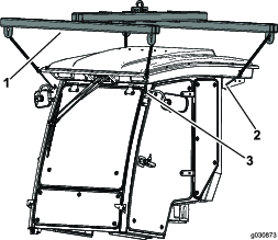
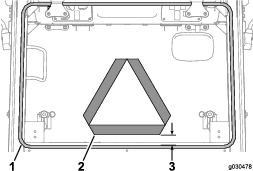
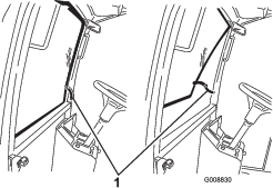
Important: Use care around the cab seals and lights (Figure 58). If you are using a pressure washer, keep the washer wand at least 0.6 m (2 ft) away from the machine. Do not use the pressure washer directly on the cab seals and lights or under the rear overhang.
Cleaning the Cab Air Filters
| Maintenance Service Interval | Maintenance Procedure |
|---|---|
| Every 250 hours |
|
-
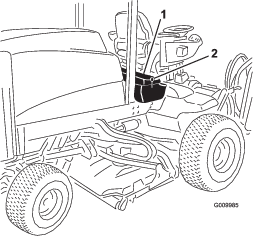
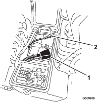
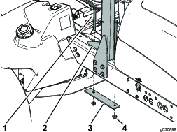
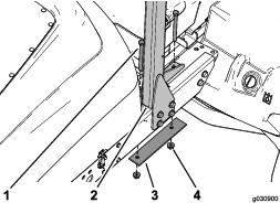
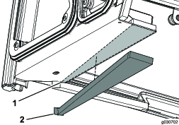
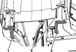
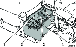
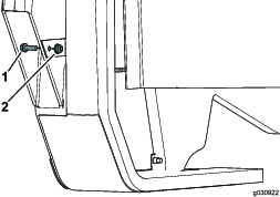
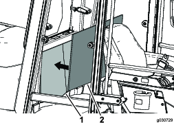
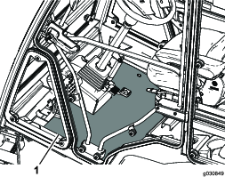
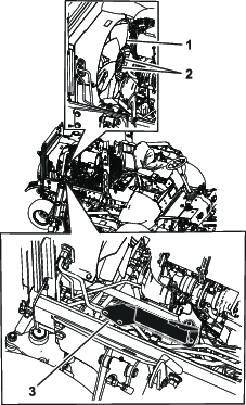
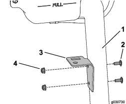
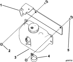
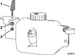
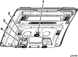
Remove the screws and grates from both the in-cab and rear cab air filters (Figure 59 and Figure 60).
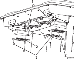
-
Clean the filters by blowing clean, oil-free, compressed air through them.
Important: If either filter has a hole, tear, or other damage, replace the filter.
-
Install the filters and the grate with the thumbscrews.
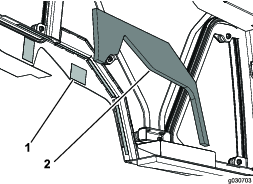
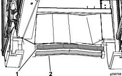
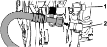
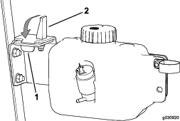
Cleaning the Cab Pre-Filter
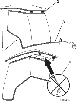
The purpose of the cab pre-filter is to prevent large debris, such as grass and leaves from entering the cab filters.
-
Rotate the screen cover down.
-
Clean the filter with water.
Note: Do not use a pressure washer.
Important: If the filter has a hole, tear, or other damage, replace the filter.
-
Allow the pre-filter to dry before installing it into the machine.
-
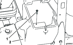
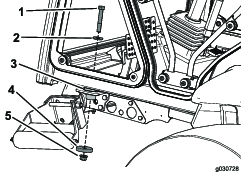
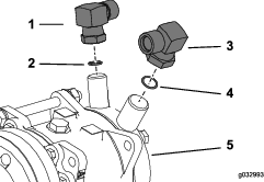
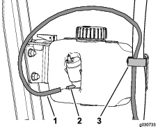
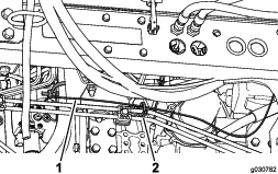
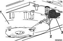
Rotate the filter screen around the tabs until the latch locks into the latch-mount assembly (Figure 61).
Cleaning the Air-Conditioning Assembly
| Maintenance Service Interval | Maintenance Procedure |
|---|---|
| Every 250 hours |
|
-
Shut off the engine and remove the key.
-
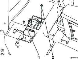
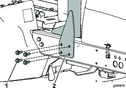
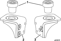
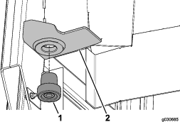
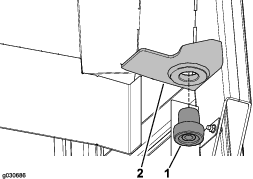
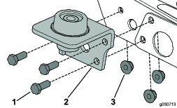
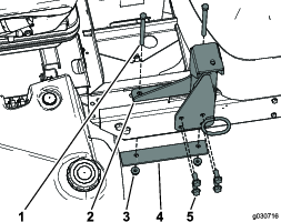
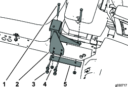
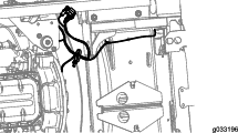
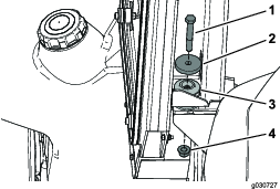
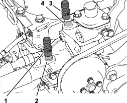
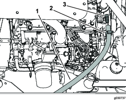
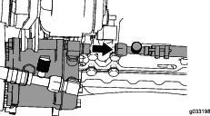
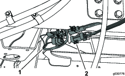
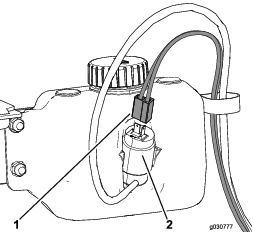
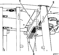
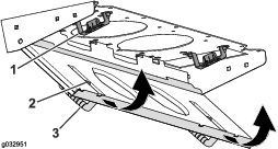
Disconnect the wire for each fan (Figure 62).
-
Remove the 2 knobs and remove the fan assembly (Figure 62).
-
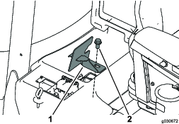
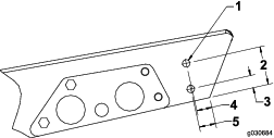
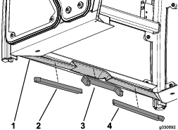
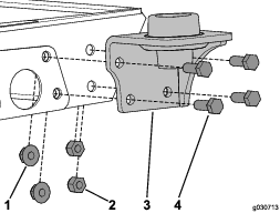
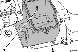
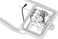
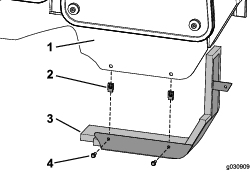
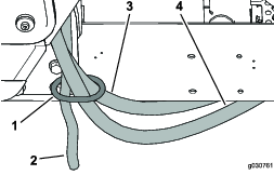
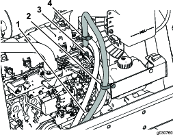
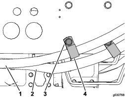
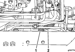
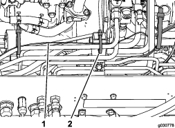
Open the 4 latches on the air-conditioning assembly and remove the screen (Figure 63).
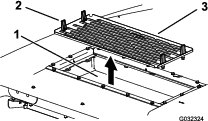
-
Remove the air filters (Figure 60).
-
Clean the air-conditioning assembly.
-
Install the air filters, screen, and fan assembly (Figure 60, Figure 63, and Figure 62).
-
Connect the wire for each fan (Figure 62).