
 , which means Caution, Warning,
or Danger—personal safety instruction. Failure to comply with
these instructions may result in personal injury or death.
, which means Caution, Warning,
or Danger—personal safety instruction. Failure to comply with
these instructions may result in personal injury or death.
Maintenance
Note: Determine the left and right sides of the machine from the normal operating position.
Recommended Maintenance Schedule(s)
| Maintenance Service Interval | Maintenance Procedure |
|---|---|
| Before each use or daily |
|
| Every 50 hours |
|
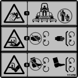
Caution
If you leave the key in the ignition switch, someone could accidently start the engine and seriously injure you or other bystanders.
Remove the key from the ignition and disconnect the wire from the spark plug before you do any maintenance. Set the wire aside so that it does not accidentally contact the spark plug.
Greasing the Bearings
| Maintenance Service Interval | Maintenance Procedure |
|---|---|
| Every 50 hours |
|
If you operate the machine under normal conditions, use No. 2 lithium grease to lubricate all bearings and bushings at the specified maintenance interval. Lubricate bearings and bushings immediately after every washing, regardless of the interval listed.
The grease fitting locations and quantities are as follows:
-
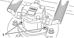
Cutting unit spindle-shaft bearings (2 per cutting unit)—Figure 10
Note: You can use either fitting, whichever is more accessible. Pump grease into the fitting until a small amount appears at bottom of the spindle housing (under the cutting unit).
-
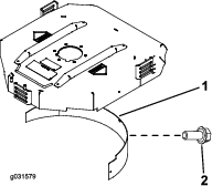
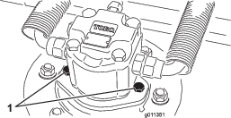
Rear-roller bearings (2 per cutting unit)—Figure 11
Note: Ensure that the grease groove in each roller mount aligns with the grease hole in each end of the roller shaft. To help align the groove and hole, there is also an alignment mark on 1 end of the roller shaft.
Separating the Cutting Unit from the Traction Unit
-
Position the machine on a level surface, lower the cutting units to the floor, turn the key in the switch to the OFF position, and engage the parking brake.
-
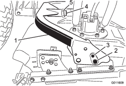
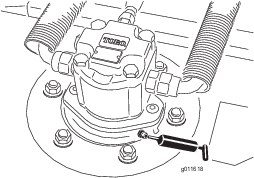
Disconnect and remove the hydraulic motor from the cutting unit (Figure 12). Cover the top of the spindle to prevent contamination.
-
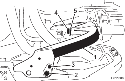
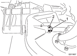
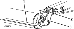
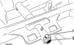
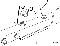
Remove the lynch pin securing the deck-carrier frame to the lift-arm pivot pin (Figure 13).
-
Roll the cutting unit away from the traction unit.
Mounting the Cutting Unit to the Traction Unit
Servicing the Cutting Blades
Blade Safety
-
Inspect the blade periodically for wear or damage.
-
Use care when checking the blades. Wrap the blades or wear gloves, and use caution when servicing the blades. Only replace or sharpen the blades; never straighten or weld them.
-
On multi-bladed machines, take care as rotating 1 blade can cause other blades to rotate.
Servicing the Blade Plane
The rotary deck comes from the factory preset at 5 cm (2 inches) height of cut and blade rake of 7.9 mm (0.310 inch). The left and right heights are also preset to within ± 0.7 mm (0.030 inch) of the other.
The cutting deck is designed to withstand blade impacts without deformation of the chamber. If a solid object is struck, inspect the blade for damage and the blade plane for accuracy.
Inspecting the Blade Plane
-
Remove the hydraulic motor from the cutting deck and remove the cutting deck from the tractor.
-
Use a hoist (or minimum of 2 people) and place the cutting deck on a flat table.
-
Mark 1 end of the blade with a paint pen or marker. Use this end of the blade to check all heights.
-
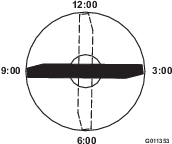
Position the cutting edge of the marked end of the blade at 12 o’clock (straight ahead in the direction of mowing) (Figure 14) and measure height from table to cutting edge of blade.
-
Rotate the marked end of the blade to the 3 and 9 o’clock positions (Figure 14) and measure the heights.
-
Compare the 12 o’clock measured height to the height-of-cut setting. It should be within 0.7 mm (0.030 inch). The 3 and 9 o’clock heights should be 1.6 to 6.0 mm (0.06 to 0.24 inch) higher than the 12 o’clock setting and within 1.6 to 6.0 mm (0.06 to 0.24 inch) of each other.
Note: If any of these measurements are not within specification, proceed to Adjusting the Blade Plane.
Adjusting the Blade Plane
Start with the front adjustment (change 1 bracket at a time).
-
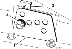
Remove the height-of-cut bracket (front, left, or right) from the deck frame (Figure 15).
-
Adjust 1.5 mm (0.060 inch) shims and/or 0.7 mm (0.030 inch) shim between the deck frame and bracket to achieve the desired height setting (Figure 15).
-
Install the height-of-cut bracket to the deck frame with the remaining shims assembled below the height-of-cut bracket.
-
Secure the socket-head bolt/spacer and flange nut.
Note: Socket-head bolt/spacer are held together with thread-locking adhesive to prevent the spacer from falling inside the deck frame.
-
Verify the 12 o’clock height and adjust if needed.
-
Determine if only 1 or both (right and left) height-of-cut brackets need to be adjusted. If the 3 or 9 o’clock side is 1.6 to 6.0 mm (0.06 to 0.24 inch) higher than the new front height then no adjustment is needed for that side. Adjust the other side to within 1.6 to 6.0 mm (0.06 to 0.24 inch) of the correct side.
-
Adjust the right and/or left height-of-cut brackets by repeating steps 1 through 3.
-
Secure the carriage bolts and flange nuts.
-
Again, verify the 12, 3, and 9 o’clock heights.
Removing and Installing the Cutting-Unit Blade(s)
Replace the blade if it hits a solid object, is out of balance, or is bent. Always use genuine Toro replacement blades to ensure safety and optimum performance.
-
Park the machine on a level surface, raise the cutting unit to the transport position, engage the parking brake, shut off the engine, and remove the key.
Note: Block or lock the cutting unit to prevent it from accidentally falling.
-
Grasp the end of the blade using a rag or thickly-padded glove.
-
Remove the blade bolt, anti-scalp cup, and blade from the spindle shaft (Figure 16).

-
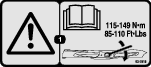
Install the blade, anti-scalp cup, and blade bolt and tighten the blade bolt to 115 to 149 N∙m (85 to 110 ft-lb).
Important: The curved part of the blade must be pointing toward the inside of the cutting unit to ensure proper cutting.
Note: 7After striking a foreign object, torque all spindle-pulley nuts to 115 to 149 N∙m (85 to 110 ft-lb).
Inspecting and Sharpening the Blade
-
Raise the cutting deck to the transport position, turn the key in the ignition switch to the OFF position, and engage the parking brake.
-
Block the cutting deck to prevent it from falling accidentally.
-
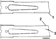
Examine the cutting ends of the blade carefully, especially where the flat and curved parts of the blade meet (Figure 17).
Note: Since sand and abrasive material can wear away the metal that connects the flat and curved parts of the blade, check the blade before using the machine.
-
If wear is noticed (Figure 17), replace the blade; refer to Servicing the Blade Plane.
Danger
If the blade is allowed to wear, a slot will form between the sail and flat part of the blade (Figure 17). Eventually a piece of the blade may break off and be thrown from under the housing, possibly resulting in serious injury to yourself or bystanders.
-
Inspect the blade periodically for wear or damage.
-
Always replace a worn or damaged blade.
-
-
Inspect the cutting edges of all blades. Sharpen the cutting edges if they are dull or nicked. Sharpen only the top of the cutting edge and maintain the original cutting angle to make sure that it is sharp (Figure 18).
-
If dull or nicked, sharpen only the top cutting edge while maintaining the original cutting angle (Figure 18).
Note: The blade will remain balanced if the same amount of metal is removed from both cutting edges.

-
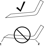
To check the blade for being straight and parallel, lay the blade on a level surface and check its ends.
Note: Position the ends of the blade slightly lower than the center, and the cutting edge lower than the heel of the blade. This blade produces a good quality of cut and requires minimal power from the engine. By contrast a blade that is higher at the ends than the center, or if cutting edge is higher than the heel, the blade is bent or warped and must be replaced.
-
Install the blade, sail facing toward cutting deck, with the anti-scalp cup and blade bolt. Torque the blade bolt to 115 to 149 N∙m (85 to 110 ft-lb).
Checking the Blade Stopping Time
| Maintenance Service Interval | Maintenance Procedure |
|---|---|
| Before each use or daily |
|
The blades of the cutting deck should come to a complete stop in approximately 5 seconds after you shut down the cutting-deck-engagement switch.
Note: Make sure that the decks are lowered onto a clean section of turf or hard surface to avoid thrown dust and debris.
-
Have a second person stand back from the deck at least 6 m (20 feet) and watch the blades on 1 of the cutting decks.
-
Shut the cutting decks down and record the time it takes for the blades to come to a complete stop.
Note: If this time is greater than 7 seconds, the braking valve needs adjustment. Call your authorized Toro distributor for assistance in making this adjustment.
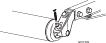
Servicing the Front Roller
Inspect the front roller for wear, excess wobble, or binding. Service or replace the roller or components if any of these conditions exist.
Disassembling the Front Roller
-
Remove the roller-mounting bolt (Figure 20).
-
Insert a punch through the end of the roller housing and drive the opposite bearing out by alternating taps to the opposite side of inner bearing race. There should be a 1.5 mm (0.060 inch) lip of inner race exposed.

-
Push the second bearing out in press.
-
Inspect the roller housing, bearings, and bearing spacer for damage (Figure 20). Replace any damaged components and assemble them.
Assembling the Front Roller
-
Press the first bearing into the roller housing (Figure 20). Press on the outer race only or equally on the inner and outer race.
-
Insert the spacer (Figure 20).
-
Press the second bearing into the roller housing (Figure 20). Pressing equally on the inner and outer race until the inner race contacts the spacer.
-
Install the roller assembly into the cutting-unit frame.
-
Verify that there is no more than a 1.5 mm (0.060 inch) gap between roller assembly and the roller mount brackets of the cutting-unit frame. If there is a gap over 1.5 mm (0.060 inch), install enough 5/8-inch diameter washers to take up the slop.
Important: Securing the roller assembly with a gap larger than 1.5 mm (0.060 inch) creates a side load on the bearing and can lead to premature bearing failure
-
Torque the mounting bolt to 108 N∙m (80 ft-lb).