Installation
Preparing the Machine
-
Park the machine on a level surface.
-
Shift the transmission lever to the P (Park) position.
-
Shut off the engine and remove the key.
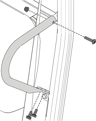
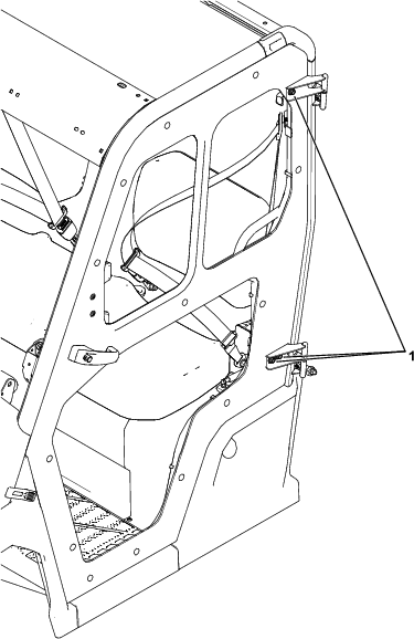
Removing the Shoulder Restraints
Remove the shoulder restraints as shown in Figure 1.
Installing the Door-Strut Brackets
Parts needed for this procedure:
| Left door-strut bracket | 1 |
| Right door-strut bracket | 1 |
| Strut mount | 2 |
| Locknut (5/16 inch) | 2 |
-
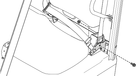
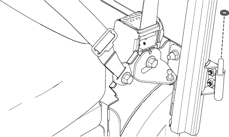
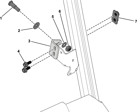
Remove the flange-head bolt (7/16 x 1 inch) and locknut (7/16 inch) securing the seat-belt retractor (Figure 2).
-
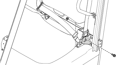
Using the previously removed flange-head bolt (7/16 x 1 inch) and locknut (7/16 inch), secure the left door-strut bracket to the seat belt bracket (Figure 3).
-
Torque the flange-head bolt (7/16 x 1 inch) and locknut (7/16 inch) to 70 N∙m (52 ft-lb).
-
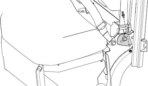
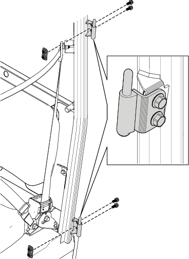
Secure a strut mount to the left door-strut bracket using a locknut (5/16 inch) as shown in Figure 4.
-
Torque the locknut (5/16 inch) to 23 N∙m (200 in-lb).
-
Repeat this procedure on the right side of the machine.
Installing the Doors
Parts needed for this procedure:
| Left door | 1 |
| Right door | 1 |
| Left door hinge | 2 |
| Right door hinge | 2 |
| Flange-head bolt (M8 x 20 mm) | 12 |
| Nut plate | 6 |
| Gas spring | 2 |
| Latch bracket | 2 |
| Belleville washer | 2 |
| Flat washer | 2 |
| Striker pin | 2 |
| Hex nut | 2 |
-
Loosely secure the 2 left door hinges to the door-pivot bracket on the ROPS using 4 flange-head bolts (M8 x 20 mm) and 2 nut plates (Figure 5).
Align the top and bottom hinge pins and tighten the 4 flange-head bolts (M8 x 20 mm) to prevent movement.
Note: You will torque the bolts during step 11.
-
Install a spacer washer onto each left door hinge (Figure 6).
-
Install the left door onto the hinges.
-
Loosen the 3 door hinge hex-head bolts (Figure 7).
With the door closed, align the door to the vehicle opening and ensure that there is a uniform gap around the perimeter of the door. After you reach the proper placement, tighten the 3 hex-head bolts.
Note: You will torque the bolts during step 11.
-
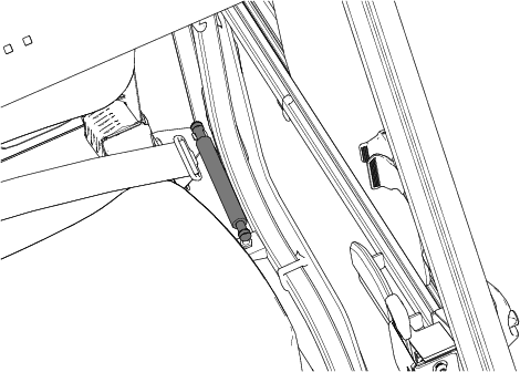
Secure a gas spring to the left strut mounts (Figure 8).
Ensure that you orient the gas spring as shown in Figure 8.
-
Close the left door.
-
Use 2 people to confirm that the door perimeter gap is uniform.
If necessary, repeat step 6 to adjust the door.
-
When the door properly aligns with the ROPS, torque the 4 flange-head bolts (M8 x 20 mm) shown in Figure 5 to 26 N∙m (230 in-lb).
Then, torque the 3 door hinge hex-head bolts (M8 x 25 mm) shown in Figure 7 to 26 N∙m (230 in-lb).
-
Open the left door.
-
Loosely secure a latch bracket to the left door-latch bracket using 1 nut plate, 2 flange-head bolts (M8 x 20 mm), 1 Belleville washer, 1 flat washer, 1 striker pin, and 1 hex nut as shown in Figure 9.
Ensure that you orient the curved portion of the Belleville washer away from the latch bracket.
-
Orient the striker pin in the center of the door latch and torque the hex nut on the striker pin to 51 N∙m (38 ft-lb).
-
Open the window on the left door to gain access to the latch bracket assembly.
-
While standing outside the vehicle, gently close the door and ensure that the striker pin engages with the latch in the vertical position. Adjust the latch bracket up or down as needed.
After the bracket is in the desired location, torque the 2 flange-head bolts (M8 x 20 mm) to 26 N∙m (230 in-lb).
-
To ensure that the door is properly preloaded (on the striker pin), you may need to adjust the striker pin.
The door latch should click twice when the door is shut and adjusted properly. Move the striker pin inward or outward until you reach the desired seal tightness, along with the double-click of the door latch.
The closed door should not rattle when pulling on the door handle.
Note: Some force is required when shutting the door and having a proper seal.
-
Repeat this procedure on the right side of the machine.