Installation
Preparing the Machine
-
Park the machine on a level surface.
-
Engage the parking brake.
-
Shut off the machine and remove the key.
-
Turn the service-disconnect switch to the OFF position; refer to the machine Operator’s Manual.
Installing the Signal Lights
Parts needed for this procedure:
| Signal light | 2 |
| Signal-light bracket—for machines with a Brush Guard Kit installed | 2 |
| Signal-light bracket—for machines without a Brush Guard Kit installed | 2 |
| Phillips-head screw (#10 x 1-1/4 inches) | 8 |
| Locknut (#10) | 8 |
| Self-tapping screw (1/4 x 1/2 inch)—for machines with a Brush Guard Kit installed | 4 |
| Brake light | 2 |
| Brake-light bracket | 2 |
| Flange-head bolt (5/16 x 3/4 inch) | 4 |
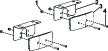
Installing the Signal Lights on the Brush Guard
-
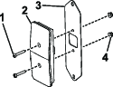
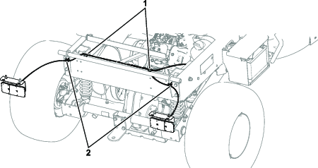
Install the signal lights onto the signal-light brackets with 2 Phillips-head screws (#10 x 1-1/4 inches) and 2 locknuts (#10) on each (Figure 1).
-
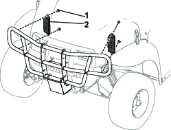
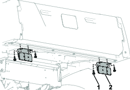
Attach the signal-light brackets onto the brush guard using 2 self-tapping screws (1/4 x 1/2 inch) on each (Figure 2).
Torque the 4 self-tapping screws (1/4 x 1/2 inch) to 452 to 508 N∙cm (40 to 45 in-lb).
Note: Ensure that the amber lens (signal lights) are positioned on top of the clear lens (position lights).
Installing the Signal Lights on the Headlight Bracket
-
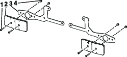
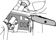
Install the signal lights onto the signal-light brackets with 2 Phillips-head screws (#10 x 1-1/4 inches) and 2 locknuts (#10) on each. Refer to Figure 3 for proper orientation.
Ensure that the clear lens (position lights) are positioned to the inside and the amber lens (signal lights) are positioned to the outside.
-
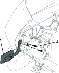
Remove the 2 existing screws from the headlight brackets on the machine (Figure 4).
-
Attach the signal-light brackets onto the headlight brackets using the existing screws on the machine (Figure 4).
Installing the Brake Lights
-
Install the brake lights onto the brake-light brackets with 2 Phillips-head screws (#10 x 1-1/4 inches) and 2 locknuts (#10) on each. Refer to Figure 5 for proper orientation.
Ensure that the red lens (brake lights) are positioned to the inside and the amber lens (signal lights) are positioned to the outside.
-
Attach the brake-light brackets onto the bottom of the plastic cargo bed using 2 flange-head bolts (5/16 x 3/4 inch) on each (Figure 6).
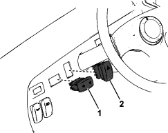
Installing the Switches
Parts needed for this procedure:
| Turn signal switch | 1 |
| Brake signal switch | 1 |
Installing the Flasher Module and Brake Switch
Parts needed for this procedure:
| Flasher module | 1 |
| Hex-head screw (#10 x 3/4 inch) | 1 |
| Brake switch | 1 |
| Hex-head screw (#6) | 2 |
| Locknut (#6) | 2 |
-
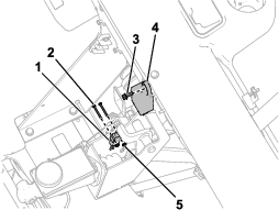
Install the flasher module to the dash reinforcement with a hex-head screw (#10 x 3/4 inch) as shown in Figure 9.
-
Install the brake switch to the pedal assembly using 2 hex-head screws (#6) and 2 locknuts (#6) as shown in Figure 9.
Note: The MDX-D is already equipped with a brake switch. Stack the new brake switch on top of the existing switch.
-
Make sure that the brake pedal arm is aligned and makes contact with the brake switch button when you release the pedal.
-
Check the depth of the brake switch button while the brake switch is engaged.
Note: The switch should be adjusted to allow the button to be depressed but not bottomed out when the brake pedal is released and the button should be extended with clearance when the brake is applied.
-
Verify the alignment and actuation of the switch by applying and releasing the brake.
Installing the Front Wire Harness
Parts needed for this procedure:
| Front wire harness | 1 |
| Cable tie | 4 |
| Perpendicular edge clip with tie | 3 |
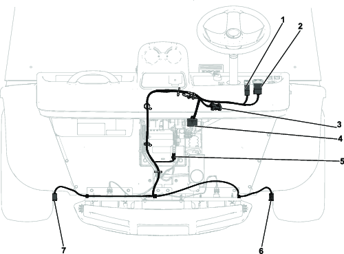
Install the front wire harness on the machine. Use Figure 10 to identify the connectors.
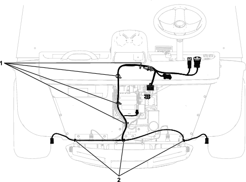
Secure the front wire harness to the machine with 4 cable ties and 3 harness clips. Refer to Figure 11 for the appropriate orientation.
Installing the Rear Wire Harness
Parts needed for this procedure:
| Rear wire harness | 1 |
| Parallel edge clip with tie | 2 |
| Perpendicular edge clip with tie | 2 |
Install the rear wire harness on the machine. Use Figure 12 to identify the connectors.
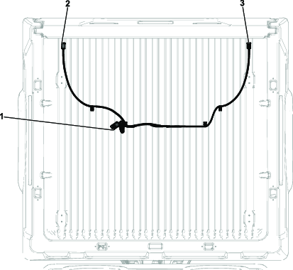
Secure the rear wire harness to the machine with 4 harness clips. Refer to Figure 13 for the appropriate orientation.
Connecting the Battery
Turn the service-disconnect switch to the ON position; refer to your machine Operator’s Manual.
Checking the Function of the Switches
Note: Get someone to help you see the lights as you test them.
-
Sit in the operator’s seat and turn on the machine.
-
Press the hazard light switch to the ON position.
Note: The hazard lights should illuminate.
-
Press the hazard light switch to the OFF position.
-
Move the turn signal to the left and right positions.
Note: The position lights should flash at the front of the machine and the taillight should flash at the back of the machine.
-
Turn off the machine and remove the key.
Note: On gas-powered machines, the hazard lights and turn signal lights work if the key is in the ON position and the is engine running.On electric machines, the hazard lights and turn signal lights work if the key is in the RUN position.
Checking the Function of the Brake Lights
Press your foot on the brake pedal and the brake lights should illuminate.
The front marker lights and rear taillights should also turn on when the headlight switch is in the ON position.