Trencher Drive
Maxi Sneaker 370 Vibratory Plow


Safety
 

Safety and Instructional Decals

Image
Safety decals and instructions are easily visible to the operator and are located near any area of potential danger. Replace any decal that is damaged or missing.
Trencher Safety Decal Locations
Graphic
G434864
  1. Decal 147-5641
  2. Decal 147-5807
Decal Part: 147-5641
Graphic
decal147-5641
  1.  Tie down
Decal Part: 147-5654
Graphic
decal147-5654
  1.  Attachment selector lever.
Decal Part: 147-5655
Graphic
147-5655
  1.  Trencher chain direction selector lever.
Decal Part: 147-5807
Graphic
decal147-5807
  1.  Cutting/dismemberment hazard, trencherkeep at least 2 m (6 ft) away.


Installation
 
Parts Required
1
Trencher control valve
2
90-degree connector
1
Straight connectors
1
45-degree connector
1
Large straight connector
1
Trencher handle
2
Nut (M10)
1
Knob
1
Trencher valve bracket
3
Bolt (M8)
3
Nut (M8)
Important  
Leave the nuts loose on connectors (1, 4, and 5) until the mating hose and hardlines are installed.
 
    Graphic
    G432647
  1. Remove the 2 covers and the engine hood from the right side of machine, set these aside.
  2. Graphic
    G432648
  3. Install the 5 connectors onto the trencher control valve .
    • 90-degree connector
    • Straight connector
    • Extended straight connector
    • 90-degree connector
    • 45-degree connector
  4. Graphic
    G432649
  5. Install the trencher handle onto the trencher control valve using the 2 nuts (M10) , and the knob .
  6. Graphic
    G432650
  7. Loosely mount the trencher control valve onto the brackettrencher valve with 3 bolts (M8) and 3 nuts (M8).
  8. Use the hardware from the cover to mount the trencher control valve and bracket to the machine.
Installing Hoses With or Without the Hydra Borer
Parts Required
1
88-inch hose
1
Hose mount bracket
1
83-inch hose
1
26-1/2 inch hose
1
Hardline (5/8 inch)
2
Abrasion sleeve (1 X 24 inches)
1
Abrasion sleeve (2 X 60 inches)
1
90 degree connector
  1. Connect the 88-inch hose to port T on the on the trencher control valve.
    Graphic
    G432651
  2. Connect the 83-inch hose to port P1 on the trencher control valve.
  3. Place the 2 abrasion sleeves (1 X 24 inches) over the 83-inch hose and the 88-inch hose, secure each end with zip ties.
  4. Place the large abrasion sleeve (2 X 60 inches) over the 2 previous sleeves and secure each end with zip ties.
  5. Route the 88-inch and 83-inch hoses down and around the front of the machine.
    Note: The hoses will be connected in a future step.
  6. Connect the 26-1/2 inch hose from the pump tandem to the 90 degree connector on port P on the trencher control valve.
    Graphic
    G432654
  7. Connect the hardline, from this kit, to the existing hardline, on the machine, and inner connector on trencher control valve in port T.
    Important  
    Ensure that the O-ring inserts into the hardline before connecting it to the hardline routing under the coolant reservoir.
     
    Graphic
    G434685
Installing the Hoses Without the Hydra Borer
Parts Required
1
16-inch hose
1
45-degree connector
1
90-degree connector
  1. Connect the 16-inch hose to the short end of the 90-degree connector.
  2. Connect the long end of the 90-degree connector to the existing hose attached to the plow control valve.
    Graphic
    G432656
  3. Connect the 16-inch hose to the 45-degree connector on the trencher control valve.
  4. Torque the bolts securing trencher valve to the bracket and the machine to 23 to 29 Nm (17 to 21 ft-lb).
    Graphic
    G432650
Installing Hoses With the Hydra Borer
Parts Required
1
Hardline
  1. Connect the short hardline to the previously installed hardline and the 45-degree connector, on the hydra borer valve, in port T.
    Important  
    Ensure that the O-ring inserts into the hardline before connecting it to the longer hardline.
     
    Graphic
    G434345
  2. Connect the longer hardline, from the hydra borer kit, from the straight fitting in the P port on the hydra borer valve to the 45-degree connector on the side of the trencher valve.
    Graphic
    G436604
Parts Required
1
Selector control valve
1
Selector valve bracket
2
Bolt (3/8 x 3-1/4 inch)
4
Flat washer
2
Nut (3/8 inch)
4
90-degree connector
2
90-degree extended connector
1
90-inch hose
1
80-inch hose
2
24-inch abrasion sleeve
1
60-inch abrasion sleeve
  1. Install the 90-degree extended connectors and the 90-degree connectors onto the selector control valve.
    Graphic
    G432659
  2. Remove the hoses on the existing bulkhead behind the console. Discard the bracket , bulkhead , and plate . Retain the bolts and nuts .
    Graphic
    G432660
  3. Use the 2 bolts (3/8 x 3-1/4 inches), 4 washers , and 2 bolts (3/8 inch) to mount the selector control valve to the selector valve bracket.
    Graphic
    G432661
  4. Torque the bolts to 37 to 45 Nm (27 to 33 ft-lb).
  5. Use the hardware from the cover to mount the selector control valve and bracket to the machine.
    Graphic
    G435141
  6. Torque the bolts to 51 to 65 Nm (38 to 48 ft-lb).
  7. Install the hoses from the bulkhead to the selector control valve.
    1. Move hose to port C2 .
    2. Move hose to port C1 .
    3. Move hose to port A .
    4. Move hose to port B .
    Graphic
    G435011
  8. Place the 2 abrasion sleeves (24 inches) over the 80-inch and 90-inch hoses and secure each end with zip ties.
  9. Place the large abrasion sleeve (60-inch) over the 2 previous sleeves and secure each end with zip ties.
  10. Connect the 90-inch hose to the lower left connector, port C4, on the selector control valve.
  11. Connect the 80-inch hose to the lower right connector, port C3, on the selector control valve.
    Graphic
    G435864
  12. Route the 2 houses around the front of the machine to the other side.
    Note: The hoses will be connected in a future step.
Parts Required
1
Side plate extension
4
Hex head bolt (3/8 x 1 inch)
1
Button head bolt (3/8 x 1 inch)
5
Locknut (3/8 inch)
3
P-Clamp (2-1/2 inches)
1
Attachment frame
3
Bolt (1/2 X 1-1/ 4 inches)
2
Bolt (1/2 X 1-1/2 inches)
2
Locknut (1/2 inch)
    Graphic
    G437381
  1. Install the side plate extension to the ride side of machine with 1 hex head bolt (3/8 x 1 inch) , 1 button head bolt (3x/8 x 1 inch) , and 2 locknuts (3/8 inch) .
  2. Graphic
    G437380
  3. Use the other 3 bolts (3/8 x 1 inch) and 3 locknuts (3/8 inch) to secure the 3 P-clamps to the side plate extension.
  4. Graphic
    G433118
  5. Torque the bolts to 37 to 45 Nm (27 to 33 ft-lb).
  6. Remove the 2 bolts from each side of the battery tray and set them aside.
  7. Graphic
    G433117
  8. Loosely mount the trencher attachment frame with 3 bolts (1/2 X 1-1/ 4 inches), 2 lower bolts (1/2 X 1-1/2 inches), and 2 locknuts (1/2 inch). Repeat the installation of the 3 bolts (1/2 X 1-1/ 4 inches) on the other side.
  9. Secure the trencher attachment mount with the bolts from the battery tray.
Parts Required
2
Tapered insert (1-1/2 inch)
2
Tapered pin (1-1/2 inch)
2
Bolt (5/8 X 1-1/2 inches)
2
Washer (1/2 inch)
2
Bolt (1/2 X 1 inch)
1
Bolt (M12)
1
Tapered insert (1-1/4 inch)
1
Tapered pin (1-1/4 inch)
3
Bolt (3/8 X 1-1/4 inches)
6
Washer (3/8 inch)
3
Locknut (3/8 inch)
1
Flap - Spoils
2
90-degree connectors
1
Hose mount bracket
1
44-inch hose
1
Hose clamp
1
Bolt (5/16 x 2 inches)
Figure 1 Installation Overview
Graphic
G434672
  1. Bolt (5/8 X 1-1/2 inches)
  2. Tapered insert (1-1/2 inch)
  3. Tapered pin (1-1/2 inch)
  4. Washer (1/2 inch)
  5. Bolt (1/2 X 1 inch)
  6. Bolt (M12)
  7. Tapered insert (1-1/4 inch)
  8. Tapered pin (1-1/4 inch)
  1. Install the trencher pivot with 1 bolt (5/8 X 1-1/2 inches), 1 tapered insert (1-1/2 inch), tapered pin (1-1/2 inch), 1 washer (1/2 inch), and 1 bolt (1/2 X 1 inch) to right side of machine.
    Graphic
    G433245
  2. Install the other side of the trencher pivot with 1 bolt (5/8 X 1-1/2 inches), 1 tapered insert (1-1/2 inch), tapered pin (1-1/2 inch), 1 washer (1/2 inch), and 1 bolt (1/2 X 1 inch).
    Graphic
    G433411
  3. Torque the bolts (5/8 x 1-1/2 inches) to 257 to 313 Nm (189 to 231 ft-lb).
  4. Torque the bolts (1/2 x 1 inch) to 91 to 113 Nm (67 to 83 ft-lb).
  5. Torque the bolts to 91 to 113 Nm (67 to 83 ft-lb).
  6. Secure the hydraulic cylinder with a tapered pin (1-1/4 inch), tapered insert (1-1/4 inch), and a bolt (M12).
    Graphic
    G434673
  7. Torque the bolts to 83 to 103 Nm (112 to 140 ft-lb).
  8. Install the flap with 3 bolts (3/8 X 1-1/4 inches), 6 washers (3/8 inch), and 3 locknuts (3/8 inch).
    Graphic
    G434651
  9. Torque the bolts to 37 to 45 Nm (27 to 33 ft-lb).
  10. Torque the trencher attachment bolts to:
    1. 127 to 157 Nm (94 to 116 ft-lb).
    2. 127 to 157 Nm (94 to 116 ft-lb).
    Graphic
    G433117
  11. Install the 2 90-degree connectors to the hose mount bracket.
    Graphic
    G433512
  12. Using existing hardware, mount the hose mount bracket to the coolant reservoir bracket holes in the frame.
    Graphic
    G433527
  13. Place the abrasion sleeve (2 X 44 inches) over the 2 44-inch hoses.
  14. Install the 44-inch hoses from the hydraulic motor to the bulkhead on the hose mount bracket.
    1. Connect the 90-degree hose end fittings to the trencher motor.
    2. Connect the straight end fittings to the bulkhead
    Graphic
    G435243
  15. Connect the 83-inch and 88-inch hose from the trencher control valve to the connectors below the hose mount bracket.
    Graphic
    G435244
  16. Secure the hoses into the hose clamp and secure the clamp with a bolt (5/16 x 2 inches).
    Graphic
    G435863
  17. Torque the bolt to 3051 to 3729 Ncm (270 to 330 in-lb).
  18. Connect the 90-inch hose coming from port C4 on the selector control valve to the hydraulic cylinder.
    Graphic
    G432692
  19. Connect the 80-inch hose coming from the C3 port on the selector control valve to the hydraulic cylinder.
    Note: Ensure that the orifice on the connector connects to the hose.
    Graphic
    G432693
  1. Place the decal 147-5654 on the selector control valve mount and the digging chain decal 147-5655 on the control valve mount.
    Graphic
    G433799
  2. Place the chain and auger decal 147-5807 and the tie down decal 147-5641 on the attachment frame.
    Graphic
    G434864


Operation
 

Operating the Trencher Handle

    Graphic
    G433798
  1. Push the trencher handle towards the front of machine to rotate the trencher in a forward/clockwise direction.
  2. Pull the trencher handle towards the back of machine to rotate the trencher in a reverse/counterclockwise direction.

Trench

Setting Up for Trenching
  1. Fasten and adjust the seat belt.
  2. Start the machine.
  3. Drive to the starting point. Move in line with the planned trench.
  4. Lower the boom to just above the ground.
  5. Check that the attachment and ground drive controls are in neutral.
Digging a Trench
Warning
Thrown objects can cause death or serious injury. Stay away from moving objects.
To help avoid injury:
  • Keep everyone at least 2 m (6 feet) from the machine, attachments, and their range of movement.
  • Know the soil conditions and adjust the digging speed accordingly.
 
  1. Select the trencher chain direction.
    The digging chain will move.
    Danger
    Contact with moving digging teeth will cause death or serious injury. Stay at least 1.8 m (6 feet) away.
    To help avoid injury:
    • Allow 1 m (3 feet) between the digging teeth and an obstacle. The machine may jerk when digging starts.
    • Keep everyone at least 2 m (6 feet) from the machine, attachments, and their range of movement.
    • Ensure that the parking brake is engaged.
    • Trench cave-in or material caught in the digging chain can result in contact with the digging teeth.
     
  2. Set the throttle to Fast.
  3. Slowly lower the digging boom to the desired trench depth.
  4. Pull the ground drive controls to drive the machine in the reverse.
  5. Set the speed.
    Important  
    • Do not make sharp turns. Lower the boom to its full depth when turning.
    • If an object becomes lodged in the chain, stop the chain movement and raise the boom slightly. Reverse the chain direction. If the object must be removed manually, turn the engine off and engage the parking brake.
     
    Note:
    • Always start trenching with the ground drive speed set to Low.
    • Always operate the trencher while driving in reverse.
    • Increase the ground drive speed only as the soil conditions permit.
    • Operate the engine at full throttle when working.
Finishing the Trenching Job
  1. When the trench is complete, stop machine movement.
  2. Set the throttle to Slow.
  3. Raise the boom.
  4. As the boom clears the top of the trench, set the trencher control lever to Neutral.
  5. Drive a short distance away from the work site.
  6. Engage the parking brake.
  7. Shut off the machine.

Trench Systems and Equipment

Chain Selection
These charts are meant as a guideline only. No one chain type works well in all conditions. Contact your Authorized Service Dealer for soil conditions and chain recommendations for your area. Ask for the latest Chain, Teeth, and Sprockets Parts Catalog.
  • 1 = best
  • 2 = better
  • 3 = good
  • 4 = not recommended
Soil
Description
Sandy soil
Sugar sand, blow sand, or other soils where sand is the predominant component
Soft soil
Sandy loam
Medium soil
Loams, loamy clays
Hard soil
Packed clays, gumbo, all compacted soils
Rocky soil
Chunk rock, glacial till, cobble, rip rap, gravel
Sticky soil
Gumbo, sticky clays
Chain
Sandy Soil
Soft Soil
Medium Soil
Hard Soil
Rocky Soil
Sticky Soil
2pitch cup tooth
2
3
1
1
3
4
4pitch cup tooth
3
1
2
3
4
1
Alternating side bar
4
4
4
4
4
1
Bolt-on adapter, 2pitch
4
3
2
1
2
4
Bolt-on adapter, cup tooth combo
4
3
2
1
2
4
Chain and Tooth Maintenance
  • Always replace sprockets at the same time as the digging chain. The sprockets and the chain are designed to work together. Replacing one without the other will cause premature wear of the new part.
  • Keep the digging chain sharp. Using dull, worn teeth will decrease production and increase the shock load to the other trencher components. It can also cause chain stretch, which leads to premature wear and failure.
  • Maintain a proper amount of tension on the digging chain. If the machine is too loose or too tight, efficiency decreases and the parts wear more quickly. Overtightening will cause chain stretch and loss of machine performance.
  • Use the tooth pattern most appropriate for the digging conditions. If conditions change, contact your Authorized Service Dealer for information about the most effective chain type and tooth pattern.
Chain Type
Chain Type
Features
2pitch
More teeth for smoother cutting
4pitch
Standard chain
Alternating side bar
Prevents soil compaction on chain
Bolt-on adapters
Allows easy configuration changes
Combination
Provides pick and shovel effect


Maintenance
 
Recommended Maintenance Schedule
Maintenance
Service Interval
Maintenance Procedure
Part No.
Qty
Description
Before each use or daily
Check the digging chain.
-
-
-
Check the trencher cleaner.
-
-
-
Check the trencher mounting bolts.
-
-
-

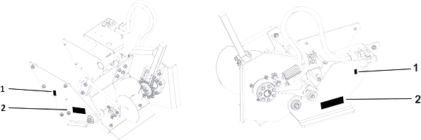
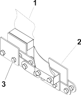
Checking Chain Components

  1. If a rock chain bit is in use, check that the bits rotate freely.
  2. Clean the chain and check the bits after each use.
  3. Replace the bit when the carbide cap or insert is worn.
  4. Graphic
    G434863
  5. If the sidebars (2) are bent or loose on the chain pins, chain spacers should be used to join the sidebars.
  6. Check the pins and bushings for wear by measuring the distance between the chain pins (3) and comparing it with the new chain.
  7. Check the teeth (1) for wear.
    Note: Replace worn teeth using Toro replacement parts and maintaining the original tooth pattern.

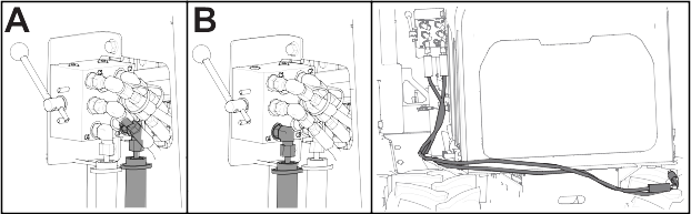
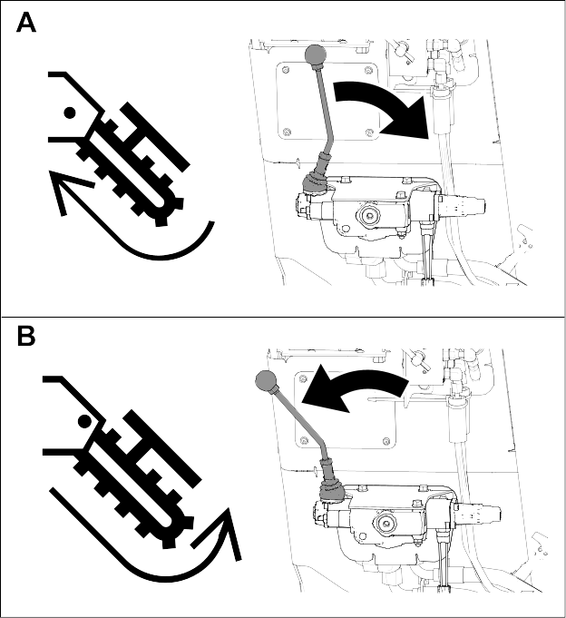
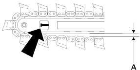
Adjusting the Digging Chain Tension

Check every 10 hours. Adjust as needed.
  1. Move the boom into a horizontal position and stop the engine.
  2. Graphic
    G434862
  3. Set the parking brake.
  4. Ensure the distance from the bottom of the boom to the chain (A) measures 3851 mm (1.52 inches).
  5. Note: Do not overtighten the chain. Overtightening will cause chain stretch, loss of machine performance, and possible premature chain failure.
    To adjust the tension, loosen the jam nut on the adjustment screw.
  6. To tighten the digging chain, turn the adjustment screw clockwise. To loosen it, turn the screw counterclockwise.
  7. When the chain is properly tensioned, tighten the jam nut.
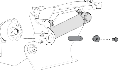
Removing the Chain

Important  
Replace the sprockets when a new chain is installed.
 
  1. Fasten and adjust the seat belt.
  2. Start the engine.
  3. Turn the digging chain until the connector pin is on top of the boom.
  4. Lower the boom to the ground.
  5. Engage the parking brake.
  6. Shut off the machine.
  7. Graphic
    G434865
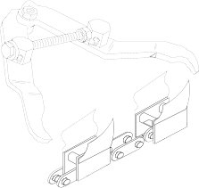
  8. Secure the chain by clamping the links on either side of the connector pin with chain jaws as shown. Squeeze the jaws to reduce pressure on the pin.
  9. Relieve chain tension.
  10. Stand clear of the chain and remove the lock key from the connector pin.
  11. Drive the connector pin out of the link.
  12. Unclamp the links. Slowly release the cable and lower the chain to the ground.
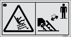
    Warning
    Raised component. Crushing can cause death or serious injury. Stay away. Use correct equipment and procedures.
     
  13. Lay the chain on the ground with the teeth down.

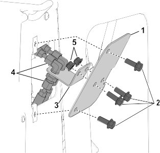
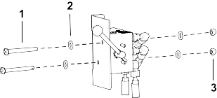
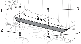
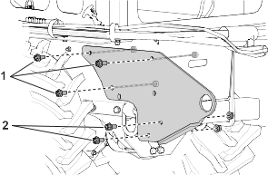
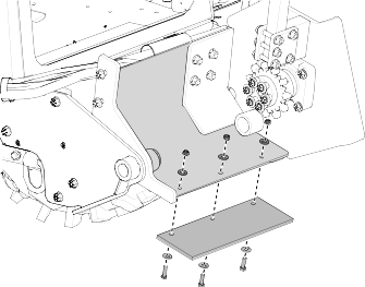
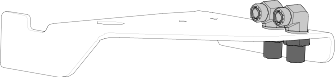
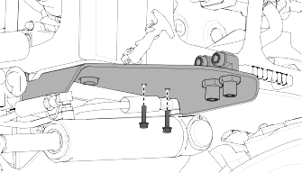
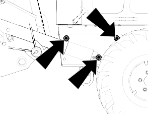
Checking the Trencher Mounting Bolts

  1. Check the bolts every 10 hours. Tighten them as needed.
    Graphic
    G433379