You must install a Rollover Protection System (ROPS) in order to install the following kit(s) with the Lift Kit:
-
Bed Rack Kit, Workman GTX Series Utility Vehicles (Model No. 07031)
-
Trash Can Mounting Kit, Workman GTX Series Utility Vehicle (Model No. 07028)
You cannot install the Lift Kit with the following models, kits, and/or assemblies:
-
Workman GTX EFI Utility Vehicle with Extended Chassis (Model No. 07042EX)
-
Workman GTX Electric Utility Vehicle with Extended Chassis (Model No. 07043EX)
-
Workman GTX EFI Utility Vehicle with Extended Chassis (Model No. 07411EX)
-
Workman GTX Electric Utility Vehicle with Extended Chassis (Model No. 07412EX)
-
Fold-Down Rear Facing Seat, Workman GTX Utility Vehicle (Model No. 07123)
-
Multi-passenger Kit, Serial Number 316000001 through 316999999 Workman GTX Series Utility Vehicles (Model No. 07133)
-
Extension Kit, Workman GTX Series Utility Vehicles (Model No. 07049)
-
Utility Van Box, Workman GTX Series Utility Vehicle (Model No. 07440)
-
Deluxe Beverage Cart, Workman GTX Series Utility Vehicle (Model No. L10004)
-
Aggressive Tire Kit, Workman GTX Series Utility Vehicle (Model No. 07423)
-
Tire/Wheel Assembly 131-8319
Safety
Safety and Instructional Decals
 |
Safety decals and instructions are easily visible to the operator and are located near any area of potential danger. Replace any decal that is damaged or missing. |

Installation
Preparing the Machine
-
Park the machine on a level surface.
-
Engage the parking brake.
-
Shut off the engine and remove the key.
-
Wait for the machine to cool.
Removing the Existing Front Components
-
Chock the rear wheels to prevent machine movement. Lift the front wheels off the ground using a jack and support the front of the machine with appropriate jack stands beneath the frame.
-
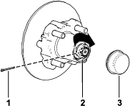
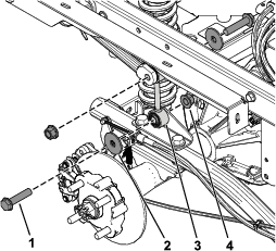
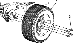
Remove the 4 lug nuts that secure the wheel to the hub (Figure 1).
-
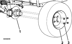
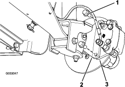
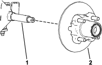
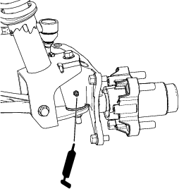
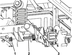
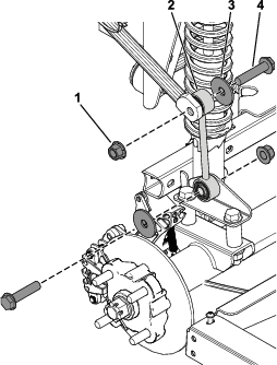
Remove the flange-head bolts (3/8 x 3/4 inch) that secure the bracket for the brake assembly to the spindle and separate the brake from the spindle (Figure 2).
Retain the caliper.
Note: Support the brake assembly before proceeding to the next step.
-
Remove the dust cap from the hub (Figure 3).
Retain the dust cap.
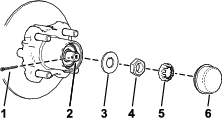
-
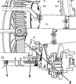
Remove the cotter pin and nut retainer from the spindle and spindle nut (Figure 3).
Retain the nut retainer and spindle nut.
-
Remove the spindle nut from the spindle, and separate the hub and rotor assembly from the spindle (Figure 3 and Figure 4).
Retain the hub and rotor.
-
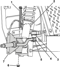
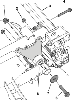
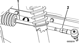
Remove the spindle assembly from the shock/spring assembly by removing the flange-head bolt (3/8 x 5 inches) and locknut (3/8 inch) as shown in Figure 5.
Retain the fasteners.
-
Remove the cotter pin and castle nut from the tie rod (Figure 5).
Retain the castle nut.
-
Repeat steps 1 through 11 on the other side of the machine.
Installing the New Front Components
Parts needed for this procedure:
| Left spindle assembly | 1 |
| Right spindle assembly | 1 |
| Aluminum wheel and tire assembly | 2 |
| Lug nut | 8 |
| Hex-head flange bolt (3/8 x 7/8 inch) | 4 |
| Cotter pin | 2 |
| O-ring | 4 |
-
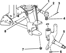
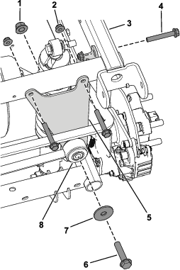
Secure the left spindle assembly to the spring/shock assembly using the previously removed flange-head bolt (3/8 x 5 inches), locknut (3/8 inch), and 2 new O-rings (Figure 6).
Torque the flange-head bolt (3/8 x 5 inches) to 68 N∙m (50 ft-lb).
-
Secure the tie rod to the spindle assembly using the previously removed castle nut and new cotter pin (Figure 6).
-
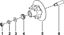
Assemble the hub and rotor onto the spindle with the rotor inboard (Figure 7).
-
Assemble the outboard bearing onto the spindle and seat the bearing to the outboard race (Figure 7).
-
Assemble the tab washer onto the spindle (Figure 7).
-
Thread the spindle nut onto the spindle and tighten the nut while rotating the hub (Figure 7).
Note: Tighten the nut and rotate the spindle until the bearings are fully seated and the hub has no linear-end movement.
-
Loosen the spindle nut until the hub rotates freely.
-
Torque the spindle nut to 170 N∙cm (15 in-lb) while rotating the hub.
-
Install the retainer over the nut and check the alignment of the slot in the retainer and the hole in the spindle for the cotter pin (Figure 8).
Note: If the slot in the retainer and the hole in the spindle are not aligned, tighten the spindle nut to align the slot and hole to a maximum torque of 226 N∙cm (20 in-lb) on the nut.
-
Install the cotter pin and bend each legs around the retainer (Figure 8).
-
Install the dust cap onto the hub (Figure 8).
-
Apply grease to the grease fitting on the spindle assembly (Figure 9).
-
Secure the caliper bracket to the spindle using 2 new hex-head flange bolts (3/8 x 7/8 inch) as shown in Figure 10.
Torque the hex-head flange bolts (3/8 x 7/8 inch) to 52 N∙m (38 ft-lb).
-
-
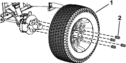
Install the aluminum wheel and tire assembly using 4 lug nuts (Figure 11).
Torque the lug nuts in a cross pattern to 115 N∙m (85 ft-lb).
-
Repeat steps 1 through 18 on the right side of the machine.
Removing the Existing Rear Components
-
Chock the front wheels to prevent machine movement. Lift the rear wheels off the ground using a jack and support the rear of the machine with appropriate jack stands beneath the frame.
-
Remove the 4 lug nuts that secure the wheel to the hub (Figure 12).
-
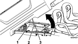
Remove the 2 hex-head flange bolts (1/2 x 2-1/4 inches), 2 washers, and 2 locknuts (1/2 inch) securing the sway-bar link assembly (Figure 13).
Retain the fasteners for later installation.
-
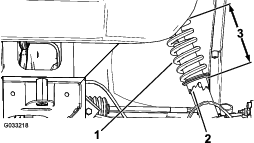
Remove the 2 hex-head flange bolts (1/2 x 2-1/4 inches) and 2 locknuts (1/2 inch) securing the shock/spring assembly (Figure 14).
Retain the fasteners for later installation.
Note: With the jack stands supporting the frame, you may use a jack to support the weight of the transaxle. This may assist with removing the 2 hex-head flange bolts (1/2 x 2-1/4 inches) and 2 locknuts (1/2 inch).
-
Right side of the machine only: remove the 3 hex-head flange bolts (3/8 x 2-1/2 inches), 3 flange nuts (3/8 inch), 1 hex-head flange bolt (1/2 x 2-1/4 inches), 1 washer, and 1 locknut (1/2 inch) securing the stabilizer bracket to the rod arm and frame tubes (Figure 15).
Retain the fasteners for later installation.
-
Repeat steps 2 through 6 on the other side of the machine.
Installing the New Rear Components
Parts needed for this procedure:
| Shock/spring assembly | 2 |
| Sway-bar link assembly | 2 |
| Stabilizer-bar bracket | 1 |
| Aluminum wheel and tire assembly | 2 |
| Lug nut | 8 |
-
Secure the shock/spring assembly using the previously removed 2 hex-head flange bolts (1/2 x 2-1/4 inches) and 2 locknuts (1/2 inch) as shown in Figure 16.
Important: For gasoline machines, set the shock/spring assembly to the lowest preload setting.For electric machines, set the shock/spring assembly in the third lowest preload setting.
-
Secure the sway-bar link assembly using the previously removed 2 hex-head flange bolts (1/2 x 2-1/4 inches), 2 washers, and 2 locknuts (1/2 inch) as shown in Figure 17.
Torque the 2 hex-head flange bolts (1/2 x 2-1/4 inches) to 115 N∙m (85 ft-lb).
-
Right side of the machine only: secure the stabilizer bracket to the frame tubes and rod arm using the previously removed 3 hex-head flange bolts (3/8 x 2-1/2 inches), 3 flange nuts (3/8 inch), 1 hex-head flange bolt (1/2 x 2-1/4 inches), 1 washer, and 1 locknut (1/2 inch) as shown in Figure 18.
Torque the 3 hex-head flange bolts (3/8 x 2-1/2 inches) to 41 N∙m (30 ft-lb).
Torque the hex-head flange bolt (1/2 x 2-1/4 inches) to 115 N∙m (85 ft-lb).
-
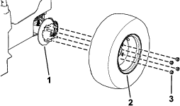
Install the aluminum wheel and tire assembly using 4 lug nuts (Figure 19).
Torque the lug nuts in a cross pattern to 115 N∙m (85 ft-lb).
-
Repeat steps 1 through 7 on the other side of the machine.
Adjusting the Front Wheel Alignment
Preparing to Adjust Camber or Toe-in
-
Check the tire pressure to ensure that the front tires are properly inflated.
-
Either add weight to the driver's seat equal to the average operator who will run the machine, or have an operator sit on the seat. The weight or operator must remain on the seat for the duration of the adjustment procedure.
-
On a level surface, roll the machine straight back 2 to 3 m (6 to 10 ft) and then straight forward to the original starting position. This allows the suspension to settle into the operating position.
Adjusting the Camber
Owner provided tools: spanner wrench, Toro Part No. 132-5069; refer to your Authorized Service Dealer.
Important: Make the camber adjustments only if you are using a front attachment or if there is uneven tire wear.
-
Check the camber alignment at each wheel; the alignment should be as close to neutral (zero) as possible.
Note: The tires should be aligned with the tread evenly on the ground to reduce uneven wear.
-
If the wheel camber is out of alignment, use the spanner wrench to rotate the collar on the shock absorber to align the wheel (Figure 20).
Adjusting the Front Wheel Toe-in
Important: Before adjusting toe-in, ensure that the camber adjustment is as close to neutral as possible; refer to Adjusting the Camber.
-
Measure the distance between both of the front tires at the axle height at both the front and rear of the front tires (Figure 21).

-
If the measurement does not fall within 0 to 6 mm (0 to 1/4 inch), loosen the jam nuts at the outer end of the tie rods (Figure 22).
-
Rotate both tie rods to move the front of the tire inward or outward.
-
Tighten the tie rod jam nuts when the adjustment is correct.
-
Ensure that there is full travel of the steering wheel in both directions.
Installing the New Dipstick Tube
Parts needed for this procedure:
| Dipstick tube | 1 |
-
Park the machine on a level surface, engage the parking brake, shut off the engine, and remove the key.
-
Raise the cargo bed to the service position by pulling the prop rod into the service position detent slot to secure the bed before installation.
-
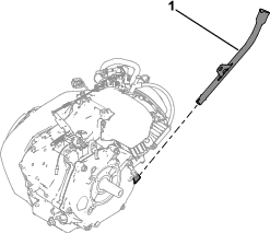
Remove the bolt securing the old dipstick tube, then remove the old dipstick tube.
Note: Dispose the used engine oil at a certified recycling center.
-
Thoroughly clean the new dipstick tube and side cover for the dipstick tube.
-
Apply the Loctite sealant onto the end of the new dipstick tube.
Important: Ensure that the Loctite completely cures before continuing. Follow the instructions from Loctite.
-
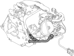
Install the new dipstick tube using the previously removed bolt.
-
Torque the bolt to 11 N•m (100 in-lb).
-
Check the engine-oil level and verify that there are no leaks.
Note: The best time to check the engine oil is when the engine is cool before it has been started for the day. If you have already run the engine, allow the oil to drain back down to the sump for at least 10 minutes before checking. If the oil level is low, add oil to bring the oil level to the Full mark. Do not overfill.
Note: The engine-oil dipstick is only accurate when the vehicle is unloaded.
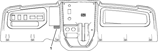
Applying the Decal
Parts needed for this procedure:
| Decal 140-2584 | 1 |
Align the decal with the bottom, right edge of warning decal 131-8414 and apply decal 140-2584 (Figure 26).