Important: If the Bagger Kit is installed on the machine, you cannot install the Universal Mount Kit.
Safety
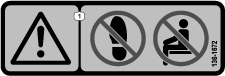
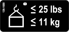
Safety and Instructional Decals
 |
Safety decals and instructions are easily visible to the operator and are located near any area of potential danger. Replace any decal that is damaged or missing. |
Installation
Preparing the Machine
-
Park the machine on a level surface.
-
Move the motion-control levers to the NEUTRAL-LOCK position.
-
Engage the parking brake.
-
Shut off the engine, remove the key, and wait for all movement to stop before you leave the operator’s position.
-
Allow the machine to cool before adjusting, servicing, cleaning, or storing it.
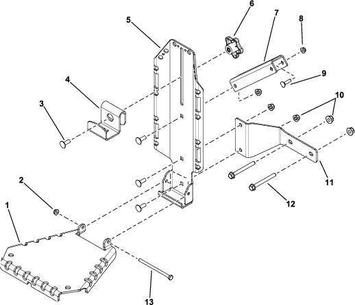
Assembling the Kit
Parts needed for this procedure:
| Main bracket | 1 |
| Top bracket | 1 |
| Bottom bracket plate | 1 |
| Top bracket plate | 1 |
| Carriage bolt (5/16 x 7/8 inch) | 4 |
| Nut (5/16 inch) | 3 |
| Knob | 1 |
| Hinge bracket | 1 |
| Nut (1/4 inch) | 1 |
| Bolt (1/4 x 4-1/4 inches) | 1 |
Assemble the kit as shown in Figure 1. Do not overtighten the bolt (1/4 x 4-1/4 inches) and nut (1/4 inch); the hinge bracket must pivot freely.
Important: Secure the bottom bracket plate to the machine before installing the hinge bracket.
Mounting the Kit to the Machine
Parts needed for this procedure:
| Bolt (5/16 x 3 inches) | 2 |
| Nut (5/16 inch) | 2 |
| Carriage bolt (1/4 x 1 inch) | 1 |
| Nut (1/4 inch) | 1 |
Mounting Locations
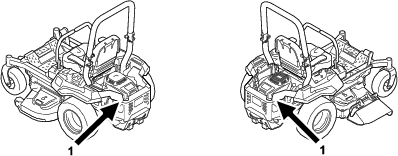
You can mount this kit in 2 locations on the machine (Figure 2). Refer to the following procedures to mount the kit in the desired location.
Mounting the Kit to the Side of the Engine Guard
Warning
The engine can become very hot. Touching a hot engine can cause severe burns.
Allow the engine to cool completely before service or making repairs around the engine area.
-
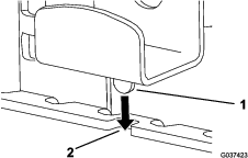
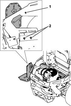
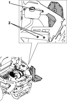
Secure the mount assembly to the side rear guard using 1 carriage bolt (1/4 x 1 inch) and 1 nut (1/4 inch) as shown in Figure 3 or Figure 4.
-
Secure the bottom of the main bracket to the engine guard using 2 bolts (5/16 x 3 inches) and 2 nuts (5/16 inch) as shown in Figure 3 or Figure 4.
Note: Remove the 2 bolts securing the lower side rear guard to make room for the mounting bracket.
Important: If you are mounting to the right side on a Z Master 4000, remove the existing bolt that secures the expansion tank to the frame. Discard this bolt and use the kit hardware to secure the bracket to the frame.
Installing a Front-Weight Kit
Parts needed for this procedure:
| Front-weight kit (sold separately) | 1 |
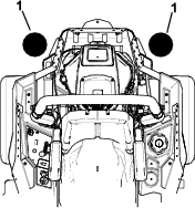
If 2 accessory-mount kits (i.e., bucket kit or universal mount kit) are added to both of the mounting locations shown in Figure 5, add a front-weight kit. Contact your Authorized Service Dealer for the front-weight kit.
Operation
Mounting Attachments
Use only Toro-approved attachments and accessories. The maximum capacity is 11.3 kg (25 lb).
Use the top bracket and hinge bracket for mounting attachments or accessories; secure them using the holes in the mounting brackets.
Secure the hinge bracket when not in use; refer to Securing the Hinge Bracket.
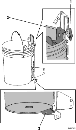
Mounting a Bucket
Note: If desired, you can remove the hinge bracket and mount the bucket using the welded support bracket.
-
Loosen the knob and raise the top bracket. Tighten the knob to hold it in place (Figure 6).
-
If you removed the hinge bracket, place the bottom lip of the bucket over the bottom ledge of the welded support bracket (Figure 6).
-
Loosen the knob and lower the top bracket as far as possible over the rim of the bucket. Tighten the knob (Figure 6).
Securing the Hinge Bracket
-
Raise the hinge bracket.
-
Loosen the knob and lower the top bracket, inserting the tab into the notch in the hinge bracket (Figure 7).
-
Tighten the knob.