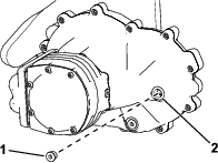
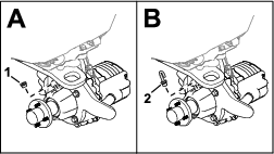

 indicates
that 3-wheel-drive model is activated.
indicates
that 3-wheel-drive model is activated.Maintenance
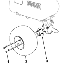
Greasing the Hub Assembly
| Maintenance Service Interval | Maintenance Procedure |
|---|---|
| Every 100 hours |
|
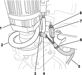
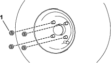
Use No. 2 lithium grease to lubricate the hub assembly. Refer to Figure 10 for the location of the hub-assembly grease fitting.
Changing the Gearbox Fluid
| Maintenance Service Interval | Maintenance Procedure |
|---|---|
| After the first 8 hours |
|
| Every 800 hours |
|
Fluid specification: SAE 80W-90
Gearbox fluid capacity: approximately 1.2 L (40 fl oz)
Preparing the Machine
-
Park the machine on a level surface.
-
Engage the parking brake.
-
Lower the cutting units.
-
Shut off the machine and remove the key.
-
Disconnect the main-power connectors; refer to your machine Operator’s Manual.
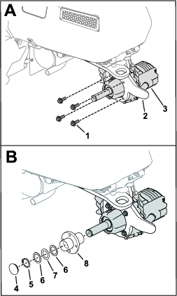
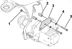
Draining the Gearbox Fluid
-
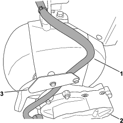
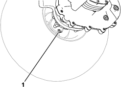
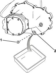
Place a drain pan under the wheel-motor assembly (Figure 11).
-
Remove the plug from the drain port (Figure 11)
Note: The drain port is located on the bottom of the gearbox.
Note: You can loosen the fill-port fitting [shown in Adding Fluid to the Gearbox] to ensure that it can be removed after you drain the fluid.
-
Allow the fluid to drain completely from the gearbox.
-
Clean the plug.
-
Install the drain plug into the drain port (Figure 11).