


Maintenance
Note: Determine the left and right sides of the machine from the normal operating position.
Maintenance Safety
-
Park machine on level ground, disengage drives, set parking brake, stop engine, and remove key. Wait for all moving parts to stop before leaving the operator’s position. Allow the machine to cool before servicing, adjusting, fueling, cleaning, or storing.
-
If you leave the key in the switch, someone could accidently start the engine and seriously injure you or other bystanders. Remove the key from the switch before you perform any maintenance.
-
Never allow untrained personnel to service machine.
-
Disconnect battery or remove spark plug wire before making any repairs. Disconnect the negative terminal first and the positive last. Reconnect positive first and negative last.
-
Keep all guards, shields, switches, and all safety devices in place and in proper working condition. Frequently check for worn or deteriorating components and replace them with genuine Exmark parts when necessary.
Warning
Removal or modification of original equipment, parts and/or accessories may alter the warranty, controllability, and safety of the machine. Unauthorized modifications to the original equipment or failure to use original Exmark parts could lead to serious injury or death. Unauthorized changes to the machine, engine, fuel or venting system, may violate applicable safety standards such as: ANSI, OSHA and NFPA and/or government regulations such as EPA and CARB.
Warning
Hydraulic fluid escaping under pressure can penetrate skin and cause injury. Fluid accidentally injected into the skin must be surgically removed within a few hours by a doctor familiar with this form of injury or gangrene may result.
-
If equipped, make sure all hydraulic fluid hoses and lines are in good condition and all hydraulic connections and fittings are tight before applying pressure to hydraulic system.
-
Keep body and hands away from pinhole leaks or nozzles that eject high pressure hydraulic fluid.
-
Use cardboard or paper, not your hands, to find hydraulic leaks.
-
Safely relieve all pressure in the hydraulic system by placing the motion control levers in neutral and shutting off the engine before performing any work on the hydraulic system.
-
-
Use care when checking blades. Wrap the blade(s) or wear gloves, and use caution when servicing them. Only replace damaged blades. Never straighten or weld them.
-
Do not rely solely on mechanical or hydraulic jacks for support. Use adequate jack stands.
-
Carefully release pressure from components with stored energy
-
Keep your hands and feet away from moving parts or hot surfaces. If possible, do not make adjustments with the engine running.
-
Keep all parts in good working condition and all hardware tightened, especially the blade-attachment hardware.
Recommended Maintenance Schedule(s)
| Maintenance Service Interval | Maintenance Procedure |
|---|---|
| After the first 5 hours |
|
| After the first 75 hours |
|
| Before each use or daily |
|
| Every 25 hours |
|
| Every 50 hours |
|
| Every 100 hours |
|
| Every 200 hours |
|
| Every 250 hours |
|
| Every 300 hours |
|
| Every 500 hours |
|
| Monthly |
|
| Yearly |
|
Periodic Maintenance
Engine Maintenance
Important: For Kawasaki and Kohler Engines, refer to the Engine Owner’s Manual for additional maintenance procedures.
Important: If you are using a machine with an Exmark engine above 5,000 ft (1500 m) for a continuous period, ensure that the High Altitude Kit has been installed so that the engine meets CARB/EPA emission regulations. The High Altitude Kit increases engine performance while preventing spark fouling, hard starting, and increased emissions. Once you have installed the kit, attach the high-altitude label next to the serial decal on the machine (reference Figure 24). Contact an Authorized Service Dealer to obtain the proper High Altitude Kit and high-altitude label for your machine. To locate a dealer convenient to you, access our web site at http://www.Exmark.com or contact our Exmark Customer Care Department at the number(s) listed in your Emission Control Warranty Statement. Remove the kit from the engine and restore the engine to its original factory configuration when running the engine under 5,000 ft (1500 m). Do Not operate an engine that has been converted for high-altitude use at a lower altitudes; otherwise, you could overheat and damage the engine. If you are unsure whether or not your machine has been converted for high altitude use, look for the following label:

Engine Safety
Warning
The engine can become very hot, especially the muffler and exhaust components. Touching a hot engine can cause severe burns.
Allow the engine to cool completely before service or making repairs around the engine area.
Do Not change the engine governor setting or overspeed the engine.
Servicing a Kawasaki
Servicing the Air Cleaner with Canister Style Air Filter
| Maintenance Service Interval | Maintenance Procedure |
|---|---|
| Every 250 hours |
|
| Every 500 hours |
|
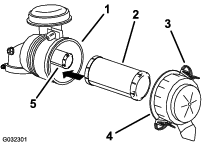
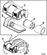
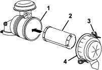
Removing the Filters
Note: Service the air cleaner more often under extremely dusty, dirty conditions.
-
Park the machine on a level surface, disengage the blade control switch, move the motion control levers to the brake position, stop the engine, remove the key, and wait until all moving parts stop before leaving the operating position.
-
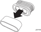
Release the latches on the air cleaner and pull the air cleaner cover off the air-cleaner body (see Figure 25).
-
Clean the inside of the air cleaner cover with compressed air.
-
Gently slide the primary filter out of the air-cleaner body.
Note: Avoid knocking the filter into the side of the body.
-
Remove the safety filter only if you intend to replace it.
Important: Do not attempt to clean the safety filter. If the safety filter is dirty, then the primary filter is damaged. Replace both filters.
-
Inspect the primary filter for damage by looking into the filter while shining a bright light on the outside of the filter.
Note: Holes in the filter appear as bright spots. If the filter is damaged, discard it.
Servicing the Primary Filter
-
If the primary filter is dirty, bent, or damaged, replace it.
-
Do not clean the primary filter.
Servicing the Safety Filter
Replace the safety filter, never clean it.
Important: Do not attempt to clean the safety filter. If the safety filter is dirty, then the primary filter is damaged. Replace both filters.
Installing the Filters
Important: To prevent engine damage, always operate the engine with both air filters and the cover installed.
-
If installing new filters, check each filter for shipping damage.
Note: Do not use a damaged filter.
-
If you are replacing the safety filter, carefully slide it into the filter body (see Figure 25).
-
Carefully slide the primary filter over the safety filter.
Note: Ensure that the primary filter is fully seated by pushing on its outer rim while installing it.
Important: Do not press on the soft inside area of the filter.
-
Install the air cleaner cover with the side indicated as up facing upward and secure the latches.
Servicing the Air Cleaner with Non-Canister Style Air Filter
| Maintenance Service Interval | Maintenance Procedure |
|---|---|
| Every 100 hours |
|
| Every 200 hours |
|
Check the air cleaner daily or before starting the engine. Check for a buildup of dirt and debris around the air cleaner system. Keep this area clean. Also check for loose or damaged components. Replace all bent or damaged air cleaner components.
Note: Operating the engine with loose or damaged air cleaner components could allow unfiltered air into the engine causing premature wear and failure.
Note: Service the air cleaner more often under extremely dusty, dirty conditions.
Removing the Elements:
-
Park the machine on a level surface, disengage the blade control switch, move the motion control levers to the brake position, stop the engine, remove the key, and wait until all moving parts stop before leaving the operating position.
-
Clean around the air cleaner cover to prevent dirt from getting into the engine and causing damage.
-
Lift the cover, loosen the hose clamp, and remove the paper element.
Cleaning the Paper Element:
-
Lightly tap the element on a flat surface to remove dust and dirt.
-
Inspect the element for tears, an oily film, and damage to the seal.
Important: Do not clean the paper element with pressurized air or liquids, such as solvent, gas, or kerosene. Replace the paper element if it is damaged or cannot be cleaned thoroughly.
Checking the Engine Oil
| Maintenance Service Interval | Maintenance Procedure |
|---|---|
| Before each use or daily |
|
Important: Do not overfill the crankcase with oil and run the engine; engine damage may result.
-
Park the machine on a level surface, disengage the blade control switch, stop the engine, engage parking brake, and remove the key.
-
Make sure the engine is stopped, level, and is cool so the oil has had time to drain into the sump.
-
To keep dirt, grass clippings, etc., out of the engine, clean the area around the oil fill cap/dipstick before removing it.
-
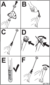
Check the engine oil level.

-
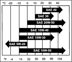
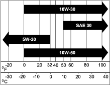
If the level is low, wipe off the area around the oil fill cap, remove cap/dipstick and add oil to the “FULL” mark on the dipstick. Exmark 4-Cycle Premium Engine Oil is recommended; refer to the following information for an appropriate API rating and viscosity. Always check the level with the dipstick before adding more oil. Do Not overfill.
-
Crankcase Capacity (when the filter is changed):
-
651–730 Models: 2.1 L (2.2 qt)
-
801 Models: 2.3 L (2.4 qt)
-
921 Models: 2.2 L (2.3 qt)
-
-
Recommended Oil Type: Exmark 4-Cycle Premium Engine Oil
– API service SJ or SL
Note: To prevent extensive engine wear or damage, always maintain the proper oil level in the crankcase. Never operate the engine with the oil level below the “ADD” mark or over the “FULL” mark on the dipstick.
-
Changing the Engine Oil
| Maintenance Service Interval | Maintenance Procedure |
|---|---|
| After the first 5 hours |
|
| Every 100 hours |
|
-
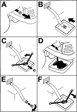
Park the machine so that the drain side is slightly lower than the opposite side to ensure the oil drains completely.
-
Start the engine and let it run until warm. This warms the oil so it drains better.
-
Disengage the blade control switch and ensure the parking brake is engaged.
-
Stop the engine, remove the key, and wait for all moving parts to stop before leaving the operating position.
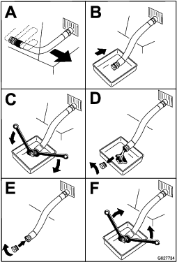
Note: Torque the plug to 14 N-m (125 in-lb).
-
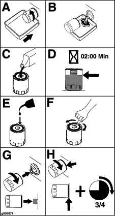
Change the engine oil filter. Apply a thin film of clean Exmark 4-Cycle Premium Engine Oil to the rubber gasket on the new filter.
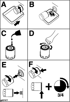
Note: Ensure the oil filter gasket touches the engine, then an extra 3/4 turn is completed.
Note: Dispose of the used oil at a recycling center.
-
Slowly pour approximately 80% of the specified oil into the filler tube—use oil recommended in the Checking the Engine Oil–Kawasaki Engine section.
-
Check the oil level; refer to Checking the Engine Oil–Kawasaki Engine section.
-
Start the engine and check for leaks.
Servicing the Spark Plug
| Maintenance Service Interval | Maintenance Procedure |
|---|---|
| Every 100 hours |
|
| Every 200 hours |
|
Ensure that the air gap between the center and side electrodes is correct before installing the spark plug. Use a spark plug wrench for removing and installing the spark plug and a gapping tool or feeler gauge to check and adjust the air gap. Install a new spark plug if necessary.
The spark plug is RFI compliant. Equivalent alternate brand plugs can also be used.
Type : NGK® BPR4ES or equivalent
Air Gap: 0.030 inch (.76 mm)
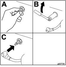
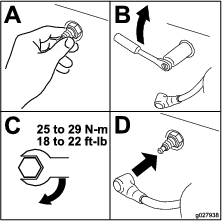
Removing the Spark Plug
-
Disengage the PTO and ensure the parking brake is engaged.
-
Stop the engine, remove the key, and wait for all moving parts to stop before leaving the operating position.
-
Disconnect the wire from the spark plug.

-
Clean around the spark plug to prevent dirt from falling into the engine and potentially causing damage.
-
Remove the spark plug and metal washer.
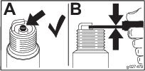
Checking the Spark Plug
-
Inspect the spark plug
Note: If you see light brown or gray on the insulator, the engine is operating properly. A black coating on the insulator usually means the air cleaner is dirty.
Important: Do Not clean the spark plug. Always replace the spark plug when it has a black coating, worn electrodes, an oily film, or cracks.
-
Check the gap between the center and side electrodes.
-
Set the gap to 0.030 inch (.76 mm).
Installing the Spark Plug
-
Install the spark plug. Make sure that the air gap is set correctly.
-
Tighten the spark plug to 16 ft-lb (22 N-m).
-
Push the wire onto the spark plug.
Check and Adjust Valve Clearance
| Maintenance Service Interval | Maintenance Procedure |
|---|---|
| Every 300 hours |
|
Refer to the Engine Owner’s Manual.
Clean Combustion Chamber
| Maintenance Service Interval | Maintenance Procedure |
|---|---|
| Every 300 hours |
|
Refer to the Engine Owner’s Manual.
Clean and Lap Valve Seating Surface
| Maintenance Service Interval | Maintenance Procedure |
|---|---|
| Every 300 hours |
|
Refer to the Engine Owner’s Manual.
Servicing a Kohler
Servicing the Air Cleaner
| Maintenance Service Interval | Maintenance Procedure |
|---|---|
| Before each use or daily |
|
| Every 25 hours |
|
| Every 50 hours |
|
| Every 100 hours |
|
This engine is equipped with a replaceable, high density paper air cleaner element. Check the air cleaner daily or before starting the engine. Check for a buildup of dirt and debris around the air cleaner system. Keep this area clean. Also, check for loose or damaged components. Replace all bent or damaged air cleaner components.
Note: Operating the engine with loose or damaged air cleaner components could allow unfiltered air into the engine, causing premature wear and failure.
Note: Service the air cleaner more often under extremely dusty, dirty conditions.
-
Park the machine on a level surface, disengage the blade control switch, move the motion control levers to the brake position, stop the engine, remove the key, and wait until all moving parts stop before leaving the operating position.
-
Remove the cover to access the air cleaner element (see Figure 35).
-
Remove the precleaner and paper element.
-
Remove the element, and gently tap the element to dislodge dirt.
Note: Do Not wash the paper element or use pressurized air, as this will damage the element.
Note: Replace a dirty, bent, or damaged element. Handle the new element carefully; do not use if the sealing surfaces are bent or damaged.
-
Wash the precleaner in warm water with detergent, rinse, and air dry.
-
Lightly oil the precleaner with new engine oil and squeeze out excess oil.
-
Clean the air cleaner base as required, and check the condition.
-
Install the precleaner over the paper element.
-
Install the precleaner and paper element onto the air cleaner base.
-
Install the cover, and secure it with the latches.
Checking the Engine Oil
| Maintenance Service Interval | Maintenance Procedure |
|---|---|
| Before each use or daily |
|
Important: Do not overfill the crankcase with oil and run the engine; engine damage may result.
-
Park the machine on a level surface, disengage the blade control switch, stop the engine, engage parking brake, and remove the key.
-
Make sure the engine is stopped, level, and is cool so the oil has had time to drain into the sump.
-
To keep dirt, grass clippings, etc., out of the engine, clean the area around the oil fill cap/dipstick before removing it.
-
Check the engine oil level.
-
If the level is low, wipe off the area around the oil fill cap, remove cap/dipstick and add oil to the “F” (FULL) mark on the dipstick. Exmark 4-Cycle Premium Engine Oil is recommended; refer to the following information for an appropriate API rating and viscosity. Always check the level with the dipstick before adding more oil. Do Not overfill.
-
Crankcase Capacity (when the filter is changed): 1.9L (2 qt)
-
Recommended Oil Type: Exmark 4-Cycle Premium Engine Oil
– API service SJ or higher
Note: To prevent extensive engine wear or damage, always maintain the proper oil level in the crankcase. Never operate the engine with the oil level below the “L”(LOW) mark or over the “F” (FULL) mark on the dipstick.
-
Changing the Engine Oil
| Maintenance Service Interval | Maintenance Procedure |
|---|---|
| After the first 5 hours |
|
| Every 100 hours |
|
-
Park the machine so that the drain side is slightly lower than the opposite side to ensure the oil drains completely.
-
Start the engine and let it run until warm. This warms the oil so it drains better.
-
Disengage the blade control switch and ensure the parking brake is engaged.
-
Stop the engine, remove the key, and wait for all moving parts to stop before leaving the operating position.
Note: Torque the plug to 14 N-m (125 in-lb).
-
Change the engine oil filter. Apply a thin film of clean Exmark 4-Cycle Premium Engine Oil to the rubber gasket on the new filter.
Note: Ensure the oil filter gasket touches the engine, then an extra 3/4 turn is completed.
Note: Dispose of the used oil at a recycling center.
-
Slowly pour approximately 80% of the specified oil into the filler tube—use oil recommended in the Checking the Engine Oil section.
-
Check the oil level; refer to Checking the Engine Oil section.
-
Start the engine and check for leaks.
Servicing the Spark Plug
| Maintenance Service Interval | Maintenance Procedure |
|---|---|
| Every 200 hours |
|
| Every 500 hours |
|
Ensure that the air gap between the center and side electrodes is correct before installing the spark plug. Use a spark plug wrench for removing and installing the spark plug and a gapping tool or feeler gauge to check and adjust the air gap. Install a new spark plug if necessary.
The spark plug is RFI compliant. Equivalent alternate brand plugs can also be used.
Type: Champion XC12YC or equivalent
Air Gap: 0.030 inch (.76 mm)
Removing the Spark Plug
-
Disengage the PTO and ensure the parking brake is engaged.
-
Stop the engine, remove the key, and wait for all moving parts to stop before leaving the operating position.
-
Disconnect the wire from the spark plug.
-
Clean around the spark plug to prevent dirt from falling into the engine and potentially causing damage.
-
Remove the spark plug and metal washer.
Checking the Spark Plug
-
Inspect the spark plug
Note: If you see light brown or gray on the insulator, the engine is operating properly. A black coating on the insulator usually means the air cleaner is dirty.
Important: Do Not clean the spark plug. Always replace the spark plug when it has a black coating, worn electrodes, an oily film, or cracks.
-
Check the gap between the center and side electrodes.
-
Set the gap to 0.030 inch (.76 mm).
Installing the Spark Plug
-
Install the spark plug. Make sure that the air gap is set correctly.
-
Tighten the spark plug to 18 to 22 ft-lb (25 to 29 N-m).
-
Push the wire onto the spark plug.
Servicing an Exmark Engine
Servicing the Air Cleaner with Canister Style Air Filter
| Maintenance Service Interval | Maintenance Procedure |
|---|---|
| Every 250 hours |
|
Note: Service the air cleaner more often under extremely dusty, dirty conditions.
-
Park the machine on a level surface, disengage the blade control switch, move the motion control levers to the brake position, stop the engine, remove the key, and wait until all moving parts stop before leaving the operating position.
-
Release the latches on the air cleaner and pull the air cleaner cover off the air-cleaner body (see Figure 44).
-
Clean the inside of the air cleaner cover with compressed air.
-
Gently slide the filter out of the air-cleaner body.
Note: Avoid knocking the filter into the side of the body.
-
Inspect the filter for damage by looking into the filter while shining a bright light on the outside of the filter.
Note: Holes in the filter appear as bright spots. If the filter is damaged, discard it.
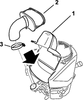
Servicing the Air Cleaner with Non-Canister Style Air Filter
| Maintenance Service Interval | Maintenance Procedure |
|---|---|
| Every 25 hours |
|
| Every 100 hours |
|
| Every 200 hours |
|
Check the air cleaner daily or before starting the engine. Check for a buildup of dirt and debris around the air cleaner system. Keep this area clean. Also check for loose or damaged components. Replace all bent or damaged air cleaner components.
Note: Operating the engine with loose or damaged air cleaner components could allow unfiltered air into the engine causing premature wear and failure.
Note: Service the air cleaner more often under extremely dusty, dirty conditions.
Removing the Elements:
-
Park the machine on a level surface, disengage the blade control switch, move the motion control levers to the brake position, stop the engine, remove the key, and wait until all moving parts stop before leaving the operating position.
-
Clean around the air cleaner cover to prevent dirt from getting into the engine and causing damage.
-
Lift the cover and rotate the air-cleaner assembly out of the engine (see Figure 45 and Figure 46).
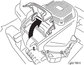
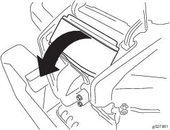
-
Separate the foam and paper elements.
Cleaning the Foam and Paper Elements:
Foam Element:
Wash the foam element with water.
Important: Replace the foam element if it is torn or worn.
Paper Element:
-
Lightly tap the element on a flat surface to remove dust and dirt.
-
Inspect the element for tears, an oily film, and damage to the seal.
Important: Do not clean the paper element with pressurized air or liquids, such as solvent, gas, or kerosene. Replace the paper element if it is damaged or cannot be cleaned thoroughly.
To learn more about the Exmark twin-cylinder engine go to https://exmark.com/engines.
Checking the Engine Oil Level
| Maintenance Service Interval | Maintenance Procedure |
|---|---|
| Before each use or daily |
|
Important: Do not overfill the crankcase with oil and run the engine; engine damage may result.
-
Park the machine on a level surface, disengage the blade control switch, stop the engine, engage parking brake, and remove the key.
-
Make sure the engine is stopped, level, and is cool so the oil has had time to drain into the sump.
-
To keep dirt, grass clippings, etc., out of the engine, clean the area around the oil fill cap/dipstick before removing it.
-
Check the engine oil level.
-
If the level is low, wipe off the area around the oil fill cap, remove cap/dipstick and add oil to the “FULL” mark on the dipstick. Exmark 4-Cycle Premium Engine Oil is recommended; refer to the following information for an appropriate API rating and viscosity. Always check the level with the dipstick before adding more oil. Do Not overfill.
-
Crankcase Capacity: 2.4 L (2.5 qt)
-
Recommended Oil Type: Exmark 4-Cycle Premium Engine Oil
– API service SF, SG, SH, SJ, SL, SM, SN, or SP

Note: To prevent extensive engine wear or damage, always maintain the proper oil level in the crankcase. Never operate the engine with the oil level below the “ADD” mark or over the “FULL” mark on the dipstick.
-
Changing the Engine Oil
| Maintenance Service Interval | Maintenance Procedure |
|---|---|
| After the first 5 hours |
|
| Every 100 hours |
|
-
Park the machine so that the drain side is slightly lower than the opposite side to ensure the oil drains completely.
-
Start the engine and let it run until warm. This warms the oil so it drains better.
-
Disengage the blade control switch and ensure the parking brake is engaged.
-
Stop the engine, remove the key, and wait for all moving parts to stop before leaving the operating position. The oil drain is located on the right side of the engine. Use either Figure 51 or Figure 52 to drain the oil from the engine.
-
Change the engine oil filter. Apply a thin film of clean Exmark 4-Cycle Premium Engine Oil to the rubber gasket on the new filter.
Note: Ensure the oil filter gasket touches the engine, then an extra 3/4 turn is completed.
Note: Dispose of the used oil at a recycling center.
-
Slowly pour approximately 80% of the specified oil into the filler tube—use oil recommended in the Checking the Engine Oil Level section.
-
Check the oil level; refer to Checking the Engine Oil Level section.
-
Start the engine and check for leaks.
Servicing the Spark Plug
| Maintenance Service Interval | Maintenance Procedure |
|---|---|
| Every 100 hours |
|
| Every 200 hours |
|
Ensure that the air gap between the center and side electrodes is correct before installing the spark plug. Use a spark plug wrench for removing and installing the spark plug and a gapping tool or feeler gauge to check and adjust the air gap. Install a new spark plug if necessary.
Type: Champion RN9YC or equivalent
Air Gap: 0.030 inch (.76 mm)
Removing the Spark Plug
-
Disengage the PTO and ensure the parking brake is engaged.
-
Stop the engine, remove the key, and wait for all moving parts to stop before leaving the operating position.
-
Disconnect the wire from the spark plug.
Note: Due to the deep recess around the spark plug, blowing out the cavity with compressed air is usually the most effective method for cleaning. The spark plug is most accessible when the blower housing is removed for cleaning.
Checking the Spark Plug
-
Inspect the spark plug
Note: If you see light brown or gray on the insulator, the engine is operating properly. A black coating on the insulator usually means the air cleaner is dirty.
Important: Do Not clean the spark plug(s). Always replace the spark plug(s) when it has: a black coating, worn electrodes, an oily film, or cracks.
-
Check the gap between the center and side electrodes.
-
Set the gap to 0.030 inch (.76 mm).
Installing the Spark Plug
-
Install the spark plug. Make sure that the air gap is set correctly.
-
Tighten the spark plug to 18.5–22.1 ft-lb (25–30 N-m).
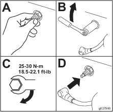
-
Push the wire onto the spark plug.
Check Valve Clearance
| Maintenance Service Interval | Maintenance Procedure |
|---|---|
| Every 300 hours |
|
Contact an Authorized Service Dealer.
-
Intake: .004–.006 inches (.10–.15 mm)
-
Exhaust: .006–.008 inches (.15–.20 mm)
Check and Clean Combustion Chamber
| Maintenance Service Interval | Maintenance Procedure |
|---|---|
| Every 300 hours |
|
Contact an Authorized Service Dealer.
Check Fuel Hose
| Maintenance Service Interval | Maintenance Procedure |
|---|---|
| Yearly |
|
Inspect for cracks, swollen, or soft fuel hose; replace if necessary.
Check Fuel Filter
| Maintenance Service Interval | Maintenance Procedure |
|---|---|
| Yearly |
|
Inspect and replace if necessary.
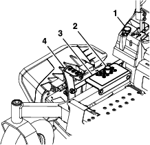
Check Battery Charge
| Maintenance Service Interval | Maintenance Procedure |
|---|---|
| Monthly |
|
Allowing batteries to stand for an extended period of time without recharging them will result in reduced performance and service life. To preserve optimum battery performance and life, recharge batteries in storage when the open circuit voltage drops to 12.4 volts.
Note: To prevent damage due to freezing, battery should be fully charged before putting away for winter storage.
Charge batteries in an open well ventilated area, away from spark and flames. Unplug charger before connecting or disconnecting from battery. Wear protective clothing and use insulated tools.
Danger
Charging or jump starting the battery may produce explosive gases. Battery gases can explode causing serious injury.
-
Keep sparks, flames, or cigarettes away from battery.
-
Ventilate when charging or using battery in an enclosed space.
-
Make sure venting path of battery is always open once battery is filled with acid.
-
Always shield eyes and face from battery.
Danger
Battery electrolyte contains sulfuric acid, which is poisonous and can cause severe burns. Swallowing electrolyte can be fatal or if it touches skin can cause severe burns.
-
Wear safety glasses to shield eyes, and rubber gloves to protect skin and clothing when handling electrolyte.
-
Do Not swallow electrolyte.
-
In the event of an accident, flush with water and call a doctor immediately.
Caution
If the ignition is in the “ON” position there is potential for sparks and engagement of components. Sparks could cause an explosion or moving parts could accidentally engage causing personal injury.
Be sure ignition switch is in the “OFF” position before charging the battery.
Check the voltage of the battery with a digital voltmeter. Locate the voltage reading of the battery in the table and charge the battery for the recommended time interval to bring the charge up to a full charge of 12.6 volts or greater.
Important: Make sure the negative battery cable is disconnected and the battery charger used for charging the battery has an output of 16 volts and 7 amps or less to avoid damaging the battery (see chart for recommended charger settings).
| Voltage Reading | Percent Charge | Maximum Charger Settings | Charging Interval |
|---|---|---|---|
| 12.6 or greater | 100% | 16 volts/7 amps | No Charging Required |
| 12.4 – 12.6 | 75–100% | 16 volts/7 amps | 30 Minutes |
| 12.2 – 12.4 | 50–75% | 16 volts/7 amps | 1 Hour |
| 12.0–12.2 | 25–50% | 14.4 volts/4 amps | 2 Hours |
| 11.7–12.0 | 0–25% | 14.4 volts/4 amps | 3 Hours |
| 11.7 or less | 0% | 14.4 volts/2 amps | 6 Hours or More |
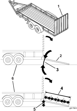
Recommended Jump Starting Procedure
-
Check the weak battery for terminal corrosion (white, green, or blue “snow”), it must be cleaned off prior to jump starting. Clean and tighten connections as necessary.
Caution
Corrosion or loose connections can cause unwanted electrical voltage spikes at anytime during the jump starting procedure.
Do Not attempt to jump start with loose or corroded battery terminals or damage to the engine may occur.
Danger
Jump starting a weak battery that is cracked, frozen, has low electrolyte level, or an open/shorted battery cell, can cause an explosion resulting in serious personal injury.
Do Not jump start a weak battery if these conditions exist.
-
Make sure the booster is a good and fully charged lead acid battery at 12.6 volts or greater. Use properly sized jumper cables (4 to 6 AWG) with short lengths to reduce voltage drop between systems. Make sure the cables are color coded or labeled for the correct polarity.
Caution
Connecting the jumper cables incorrectly (wrong polarity) can immediately damage the electrical system.
Be certain of battery terminal polarity and jumper cable polarity when hooking up batteries.
Note: The following instructions are adapted from the SAE J1494 Rev. Dec. 2001 – Battery Booster Cables – Surface Vehicle Recommended Practice (SAE – Society of Automotive Engineers).
Warning
Batteries contain acid and produce explosive gases.
-
Shield the eyes and face from the batteries at all times.
-
Do Not lean over the batteries.
Note: Be sure the vent caps are tight and level. Place a damp cloth, if available, over any vent caps on both batteries. Be sure the vehicles do not touch and that both electrical systems are off and at the same rated system voltage. These instructions are for negative ground systems only.
-
-
Connect the positive (+) cable to the positive (+) terminal of the discharged battery that is wired to the starter or solenoid as shown in .
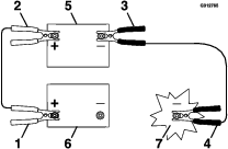
-
Connect the other end of the positive cable to the positive terminal of the booster battery.
-
Connect the black negative (–) cable to the other terminal (negative) of the booster battery.
-
MAKE THE FINAL CONNECTION ON THE ENGINE BLOCK OF THE STALLED VEHICLE (NOT TO THE NEGATIVE POST) AWAY FROM THE BATTERY. STAND BACK.
-
Start the vehicle and remove the cables in the reverse order of connection (the engine block (black) connection is the first to disconnect).
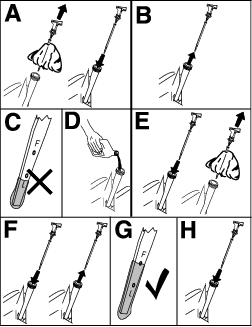
Check Mower Blades
| Maintenance Service Interval | Maintenance Procedure |
|---|---|
| Before each use or daily |
|
-
Stop engine, wait for all moving parts to stop, and remove key. Engage parking brake.
-
Lift deck and secure in raised position as stated in the Clean Grass Build-Up Under Deck section.
-
Inspect blades and sharpen or replace as required.
-
Reinstall the blades (if they were removed) in the following order:
-
Install either the splined bushing or blade:
-
X-Series:
Install the splined bushing through the blade with the bushing flange on bottom (grass) side of blade.
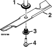
-
S- and E-Series:
Install the blade onto the spindle shaft.
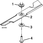
-
-
Apply lubricant to the threads of the blade bolt as needed to prevent seizing. Copper based anti-seize is preferable. Grease is an acceptable substitute.
-
Install the splined bushing/blade assembly and blade bolt washer assembly into the spindle. Install blade bolt finger tight.
-
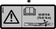
Place wrench on the top spindle nut then torque the blade bolts to 50-60 ft-lb (68-81 N-m).
Warning
Incorrect installation of the blade or components used to retain the blade can be dangerous. Failure to use all original components and assembled as shown could allow a blade or blade component to be thrown out from under the deck resulting in serious personal injury or death.
Always install the original Exmark blades, blade bushings, and blade bolts as shown.
-
Check Safety Interlock System
| Maintenance Service Interval | Maintenance Procedure |
|---|---|
| Before each use or daily |
|
Important: It is essential that operator safety mechanisms be connected and in proper operating condition prior to use.
Note: If machine does not pass any of these tests, Do Not operate. Contact an Authorized Service Dealer.
Note: To prevent engine cut-outs on rough terrain, the seat has a 1/2 second time delay before the engine begins to shutdown.
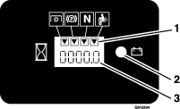
Check the Normal Engine Starting Chart
| System | ||||||
| Parking Brake | PTO | Motion Control Levers | Operator | Outcome | ||
| State of System | Engaged | Disengaged (Blades) | Both levers out (neutral lock) | In seat or out of the seat | Starter should crank | |
 |  |  |   |  |
||
Check Engine Starting Circuit Chart
Note: In the Check Engine Starting Circuit Chart, the state of system item that is bold is being checked in each scenario.
| System | |||||
| Parking Brake | PTO (Blades) | Motion Control Levers | Operator | Outcome | |
| State of System | Engaged | Disengaged | Both levers moved in, or either right or left lever moved in | Operator in seat | Starter must not crank |
| |    | |  |
|
| Disengaged | Disengaged | Both levers out (neutral lock) | Operator in seat | Starter must not crank | |
 | | | | |
|
| Engaged | Engaged | Both levers out (neutral lock) | Operator in seat | Starter must not crank | |
|  | | | |
|
Check Shutdown Circuit Chart
Note: The state of system item(s) that is bold is being checked in each scenario.
| System | ||||||
| Engine | Parking Brake | PTO (Blades) | Motion Control Levers | Operator | Outcome | |
| State of System | Running idle (1/3 throttle) | Disengaged | Disengaged | Both levers moved out (neutral lock), both levers moved in, or either right or left lever moved in | Raise off of seat (but don’t get off) | Engine must begin shutdown within 1 second |
 | | | | |  |
|
| Running idle (1/3 throttle) | Disengaged | Engaged | Both levers moved in | Raise off of seat (but don’t get off) | Engine must begin shutdown within 1 second | |
| | | | | |
|
| Running idle (1/3 throttle) | Engaged | Disengaged | Both levers moved in, or either right or left lever moved in | Operator in seat | Engine must begin shutdown within 1 second | |
| | | | | |
|
Check Rollover Protections Systems (Roll Bar) Knobs
| Maintenance Service Interval | Maintenance Procedure |
|---|---|
| Before each use or daily |
|
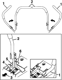
Check that both the mounting hardware and the knobs are in good working condition. Make sure the knobs are fully engaged with the ROPS in the raised position. The upper hoop of the roll bar may need to be pushed forward or pulled rearward to get both knobs fully engaged.
Check Seat Belt
| Maintenance Service Interval | Maintenance Procedure |
|---|---|
| Before each use or daily |
|
Visually inspect seat belt for wear, cuts, and proper operation of retractor and buckle. Replace before operating if damaged.
Check for Loose Hardware
| Maintenance Service Interval | Maintenance Procedure |
|---|---|
| Before each use or daily |
|
-
Stop engine, wait for all moving parts to stop, and remove key. Engage parking brake.
-
Visually inspect machine for any loose hardware or any other possible problem. Tighten hardware or correct the problem before operating.
Check Tire Pressures
| Maintenance Service Interval | Maintenance Procedure |
|---|---|
| Every 50 hours |
|
-
Stop engine, wait for all moving parts to stop, and remove key. Engage parking brake.
-
Check tire pressure in drive tires.
-
Inflate drive tires to 13 psi (90 kPa).
-
Check tire pressure in caster tires.
-
Inflate caster tires to 13 psi (90 kPa).
Check Condition Of Belts
| Maintenance Service Interval | Maintenance Procedure |
|---|---|
| Every 50 hours |
|
-
Stop engine, wait for all moving parts to stop, and remove key. Engage parking brake.
-
Remove left and right belt shields on deck and lower the deck to inspect deck drive belt.
-
Check under machine to inspect the pump drive belt.
Note: No adjustments are required for belt tension.
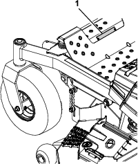
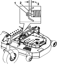
Lubricate Grease Fittings
| Maintenance Service Interval | Maintenance Procedure |
|---|---|
| Every 25 hours |
|
| Yearly |
|
Note: See chart for service intervals.
-
Stop engine, wait for all moving parts to stop, and remove key. Engage parking brake.
-
Lubricate fittings with one to two pumps of NLGI grade #2 multi-purpose gun grease.
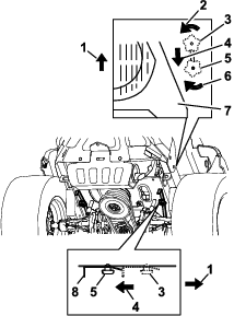
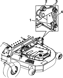
Refer to the following chart for fitting locations and lubrication schedule.
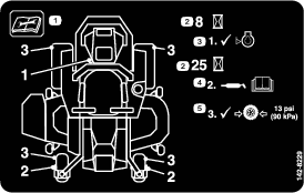
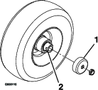
Lubrication Chart Fitting Locations Initial Pumps Number of Places Service Interval 1. Front Caster Axles (S- and E-Series Only) 1 2 25 hours 1. Front Caster Axles (X-Series) 1 2 Yearly 2. Front Caster Pivots (X-Series) 0* 2 Yearly 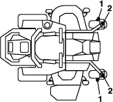
* See step 3 for special lubrication instructions on the caster pivots.
-
Lubricate caster pivots once a year. Remove hex plug and cap. Thread grease zerk in hole and pump with grease until it oozes out around top bearing. Remove grease zerk and thread plug back in. Place cap back on.
Lubricate Caster Wheel Hubs (X-Series Only)
| Maintenance Service Interval | Maintenance Procedure |
|---|---|
| After the first 5 hours |
|
| Every 500 hours |
|
-
Stop engine, wait for all moving parts to stop, and remove key. Engage parking brake.
-
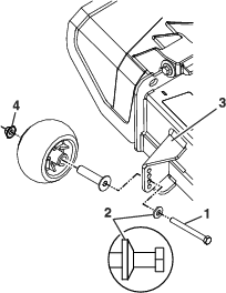
Remove caster wheel from caster forks.
-
Remove seal guards from the wheel hub.
-
Remove one of the spacer nuts from the axle assembly in the caster wheel. Note that thread locking adhesive has been applied to lock the spacer nuts to the axle. Remove the axle (with the other spacer nut still assembled to it) from the wheel assembly.
-
Pry out seals, and inspect bearings for wear or damage and replace if necessary.
-
Pack the bearings with a NLGI grade #1 multi-purpose grease.
-
Insert one bearing, one new seal into the wheel.
Note: Seals (Exmark P/N 103-0063) must be replaced.
-
If the axle assembly has had both spacer nuts removed (or broken loose), apply a thread locking adhesive to one spacer nut and thread onto the axle with the wrench flats facing outward. Do Not thread spacer nut all of the way onto the end of the axle. Leave approximately 1/8 inch (3 mm) from the outer surface of the spacer nut to the end of the axle inside the nut.
-
Insert the assembled nut and axle into the wheel on the side of the wheel with the new seal and bearing.
-
With the open end of the wheel facing up, fill the area inside the wheel around the axle full of NLGI grade #1 multi-purpose grease.
-
Insert the second bearing and new seal into the wheel.
-
Apply a thread locking adhesive to the 2nd spacer nut and thread onto the axle with the wrench flats facing outward.
-
Torque the nut to 75-80 in-lb (8-9 N-m), loosen, then re-torque to 20-25 in-lb (2-3 N-m). Make sure axle does not extend beyond either nut.
-
Reinstall the seal guards over the wheel hub and insert wheel into caster fork. Reinstall caster bolt and tighten nut fully.
Important: To prevent seal and bearing damage, check the bearing adjustment often. Spin the caster tire. The tire should not spin freely (more than 1 or 2 revolutions) or have any side play. If the wheel spins freely, adjust torque on spacer nut until there is a slight amount of drag. Reapply thread locking adhesive.
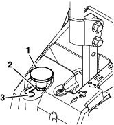
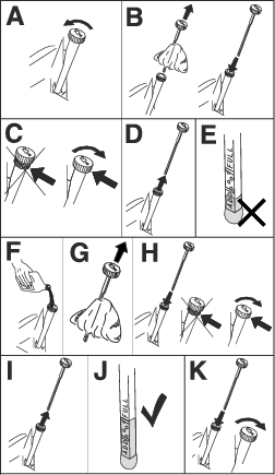
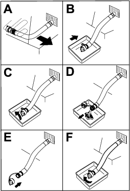
Change Fuel Filter
A fuel filter is installed between the fuel tank and the engine. Replace when necessary.
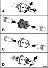
Note: It is important to reinstall the fuel line hoses and secure with plastic ties the same as they were originally installed at the factory to keep the fuel line away from components that could cause fuel line damage.
-
Stop engine, wait for all moving parts to stop, and remove key or spark plug wire(s). Engage parking brake
-
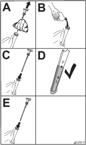
Squeeze the ends of the hose clamps together and slide them away from the filter.
-
Remove the filter from the fuel lines.
-
Install a new filter with the flow direction arrow coming from the fuel tank and pointing to the engine. Move the hose clamps close to the filter to secure it in place.
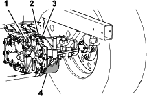
Change Hydraulic System Filter and Fluid
| Maintenance Service Interval | Maintenance Procedure |
|---|---|
| After the first 75 hours |
|
| Every 500 hours |
|
-
Park the machine on level ground. Stop engine, wait for all moving parts to stop, and allow engine to cool. Remove key and engage parking brake.
Important: Transaxles must be cool (less than 100°F (38°C)) before changing oil. Failure to allow the transaxles to cool prior to changing the oil, could result in overfilling the unit and damaging the breather assembly.
-
Locate the two filters under the transmissions. Remove filter guard screws and filter guard.
-
Carefully clean area around filters. It is important that no dirt or contamination enter hydraulic system.
-
Unscrew filters to remove and allow oil to drain from drive system.
Important: Before reinstalling new filters, apply a thin coat of Exmark Premium Hydro Oil on the surface of the filters rubber seal.
-
Install the new filter by hand; turn the filter clockwise until rubber seal contacts the filter base then tighten the filter an additional 3/4 to 1 full turn.
-
Reinstall the filter guard with the filter guard screws. Torque the screws to 65 in-lb (7 N-m).
-
Remove the top port plug. Fill the oil through the top port plug using a hand pump or through the fill port plug. Fill until it flows out of the top port opening.
Exmark Premium Hydro Oil is recommended. Refer to the chart for an acceptable alternative:
Hydro Oil Service Interval Exmark Premium Hydro Oil (Preferred) After first 75 hours*Every 500 hours thereafter Mobil 1 15W50 After first 75 hours *Every 250 hours thereafter *May need more often under severe conditions.
-
Torque the top port plug to 120 in-lb (14 N-m).
-
Torque the fill port plug to 210 in-lb (24 N-m), if it was removed to fill the transmission.
-
Raise the rear of machine up and support with jack stands (or equivalent support) just high enough to allow drive wheels to turn freely.
-
Start engine and move throttle control ahead to 1/2 throttle position. Disengage parking brake.
-
With the bypass valve open and the engine running, slowly move the directional control in both forward and reverse (5 or 6 times).
-
With the bypass valve closed and the engine running, slowly move the directional control in both forward and reverse directions (5 to 6 times). Check the oil level, and add oil as required after stopping the engine.
-
It may be necessary to repeat steps 1 and 2 until all the air is completely purged from the system. When the transaxle operates at normal noise levels and moves smoothly forward and reverse at normal speeds, then the transaxle is considered purged.
-
-
Remove the jack stands.
Note: Do Not change the hydraulic system oil (except for what can be drained when changing filter), unless it is felt the oil has been contaminated or been extremely hot.Changing oil unnecessarily could damage hydraulic system by introducing contaminants into the system.
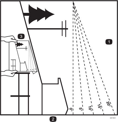
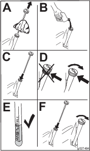
Check Spark Arrester
| Maintenance Service Interval | Maintenance Procedure |
|---|---|
| Every 50 hours |
|
Warning
Hot exhaust system components may ignite gasoline vapors even after the engine is stopped. Hot particles exhausted during engine operation may ignite flammable materials. Fire may result in personal injury or property damage.
Do Not refuel or run engine unless spark arrester is installed.
-
Stop engine, wait for all moving parts to stop, and remove key. Engage parking brake.
-
Wait for muffler to cool.
-
If any breaks in the screen or welds are observed, replace arrester.
-
If plugging of the screen is observed, remove arrester and shake loose particles out of the arrester and clean screen with a wire brush (soak in solvent if necessary). Reinstall arrester on exhaust outlet.
Thread Locking Adhesives
Thread locking adhesives such as “Loctite 242”, “Loctite 243”, or “Fel-Pro, Pro-Lock Nut Type” are used on the following fasteners:
-
ROPS spring pin housing.
-
Sheave and clutch retaining bolt in the end of engine crankshaft.
-
Hydro cross member mounting bolts
Thread locking adhesives are required for some hardware on engines — see the Engine manual.
Copper-Based Anti-seize
Copper-based anti-seize is used in the following location:
On threads of Blade Bolts. See Check Mower Blades section.
Dielectric Grease
Dielectric grease is used on all blade type electrical connections to prevent corrosion and loss of contact. Dielectric grease should not be applied to sealed connectors.
Adjustments
Note: Disengage PTO, shut off engine, wait for all moving parts to stop, engage parking brake, and remove key before servicing, cleaning, or making any adjustments to the unit.
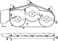
Deck Leveling
-
Position the mower on a flat surface.
-
Stop engine, wait for all moving parts to stop, and remove key. Engage parking brake.
-
Check the tire pressure in the drive tires. Proper inflation pressure for tires is 13 psi (90 kPa). Adjust if necessary.
-
Position the transport lock in the latching position.
-
Carefully rotate the blades from side to side.
-
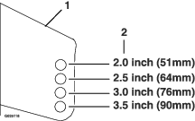
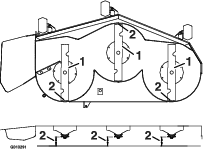
Measure between the outside cutting edges and the flat surface (Figure 66). If both measurements are not within 3/16 inch (5 mm), an adjustment is required; continue with this procedure.
-
Set anti-scalp rollers to top holes or remove completely for this adjustment.
-
For 60 Inch Decks Only:
-
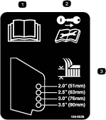
Raise the deck to the transport (5 inch (12.7 cm) cutting height) position.
-
Slowly loosen the adjusting screw on the lift assist spring until the screw can be removed (see Figure 67). Save the screw for reinstallation.
-
-
Set the height-of-cut lever to the 3 inch (76 mm) position. Place two “B” thick blocks (see Block Height and Rake Table) under the rear edge of the cutting deck skirt; one on each side of the cutting deck. Place two “A” thick blocks under each side of the front edge of the deck, but not under the anti-scalp roller brackets.
S and E-Series—Block Height and Rake Table
Front Block Height “A” Rear Block Height “B” Rake “R” 2.56 inches (6.5 cm) 2.81 inches (7.1 cm) 1/16–5/16 inch (1.6–7.9 mm) X-Series—Block Height and Rake Table
Front Block Height “A” Rear Block Height “B” Rake “R” 2.63 inches (6.7 cm) 2.88 inches (7.3 cm) 1/16–5/16 inch (1.6–7.9 mm) -
Carefully rotate the blades side to side (Figure 66).
-
Loosen the leveling adjust locking nuts (item 1 Figure 68) on all four corners so that the deck is sitting securely on all four blocks. Make sure that the slack is removed from the deck hangers and the deck lift foot lever is pushed back against the stop, then tighten the four leveling adjust locking nuts.
-
Recheck that blocks fit just snugly under the deck skirt. Make sure all attachment bolts are tight
-
Continue leveling the deck by checking the front-to-rear blade slope; refer to Adjusting the Blade Slope.
-
Recheck blades for levelness and repeat deck leveling procedure if necessary.
-
For 60 Inch Decks Only:
-
Raise the deck to the transport (5 inch (12.7 cm) cutting height) position.
-
Reinstall the lift assist spring adjusting screw that was removed in step 8.
-
Set the gap between the spring and bracket to 1.02-1.28 inch (26-33 mm).
-
Adjusting the Blade Slope
-
Check the front-to-rear blade level. If the front blade tip is not “R” (see Block Height and Rake Table in Deck Leveling) lower than the rear blade tip, adjust the blade level using the following instructions:
-
Park the machine on a level surface and disengage the blade control switch.
-
Move the motion control levers outward to the neutral position, engage the parking brake, stop the engine, remove the key, and wait for all moving parts to stop before leaving the operating position.
-
Check the air pressure of all four tires. If needed, adjust to the recommended inflation; refer to Checking the Tire Pressure in Drive System Maintenance section.
-
Check and adjust the side-to-side blade level if you have not checked the setting; refer to Deck Leveling.
-
Set the height-of-cut lever to the 3 inch (76 mm) position. Place two “B” thick blocks (see Block Height and Rake Table in Deck Leveling) under the rear edge of the cutting deck skirt; one on each side of the cutting deck. Place two “A” thick blocks (see Block Height and Rake Table in Deck Leveling) under each side of the front edge of the deck, but not under the anti-scalp roller brackets.
-
Loosen the leveling adjust locking nuts (item 1 Figure 68) on all four corners so that the deck is sitting securely on all four blocks. Make sure that the slack is removed from the deck hangers and the deck lift foot lever is pushed back against the stop, then tighten the four leveling adjust locking nuts.
-
Carefully rotate the blades so they are facing front to rear (Figure 69).
-
For 60 Inch Decks Only:
-
Raise the deck to the transport (5 inch (12.7 cm) cutting height) position.
-
Slowly loosen the adjusting screw on the lift assist spring until the screw can be removed (see Figure 67). Save the screw for reinstallation.
-
-
Measure from the tip of the front blade to the flat surface and the tip of the rear blade to the flat surface (Figure 69). If the front blade tip is not “R” (see Block Height and Rake Table in Deck Leveling) lower than the rear blade tip, adjust the front deck hanger.
-
When the front-to-rear blade slope is correct check the side-to-side level of the mower again; refer to Deck Leveling.
-
For 60 Inch Decks Only:
-
Raise the deck to the transport (5 inch (12.7 cm) cutting height) position.
-
Reinstall the lift assist spring adjusting screw that was removed in step 9.
-
Set the gap between the spring and bracket to 1.02-1.28 inch (26-33 mm) (see Figure 67).
-
Pump Drive Belt Tension
Self-tensioning - No adjustment necessary.
Deck Belt Tension
Self-tensioning - No adjustment necessary.
Adjusting the Parking Brake
| Maintenance Service Interval | Maintenance Procedure |
|---|---|
| Every 500 hours |
|
Check to make sure brake is adjusted properly. This procedure must be followed after the first 100 hours or when a brake component has been removed or replaced.
-
Drive the machine onto a level surface.
-
Disengage the blade control switch (PTO), move the motion control levers to the neutral locked position and set the parking brake.
-
Stop the engine, wait for all moving parts to stop, and remove the key.
-
Setup the machine to be pushed by hand (see Drive Wheel Release Valves in the Operation section).
-
Raise the back of the machine up and support the machine with jack stands.
-
Engage/disengage the brake and check each drive tire to make sure each brake engages/disengages.
-
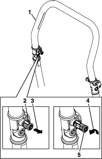
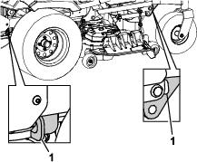
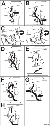
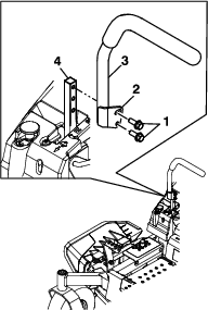
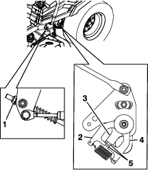
If adjustment is necessary, disengage the park brake. Remove cotter pin from the brake linkage shaft (see Figure 70).
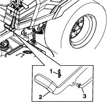
-
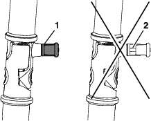
Check both spring lengths as shown in Figure 71. If adjustment is necessary, turn the top nut clockwise to shorten and counterclockwise to lengthen.
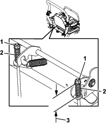
-
Push the parking brake lever all the way forward and down. Rotate the brake linkage shaft until the end aligns with hole in lever.
-
Shorten the linkage by turning it clockwise.
-
Lengthen the linkage by turning it counterclockwise.
Insert the brake linkage shaft into parking brake hole and secure with the cotter pin. Repeat step 6 and readjust if necessary.
-
-
When adjustment is complete, remove the jack stands or equivalent support and lower the machine.
-
Place the machine into the “operating” position. Refer to the Drive Wheel Release Valves section in Operation.
Motion Control Handle Adjustment
Adjusting the height:
The motion control levers can be adjusted higher or lower for maximum operator comfort.
-
Remove the hardware holding the control lever to the control arm shaft.
-
Move the control lever to the next set of holes. Secure the lever with the hardware.
-
Repeat the adjustment for the opposite control lever.
Adjusting the Tilt
The motion control levers can be tilted fore or aft for maximum operator comfort.
-
Loosen the upper bolt holding the control lever to the control arm shaft.
-
Loosen the lower bolt just enough to pivot the control lever fore or aft. Tighten both bolts to secure the control in the new position.
-
Repeat the adjustment for the opposite control lever.
Full Forward Tracking Adjustment
If the machine travels or pulls to one side, when the motion control levers are in the full forward position, adjust the tracking screw.
-
Insert a 3/16 inch hex wrench through the access hole on the front cover panel, rotate the tracking screw clockwise or counterclockwise to adjust the travel of the lever.
-
Drive the machine and check the full forward tracking.
-
Repeat steps 1 and 2 until desired tracking is obtained.
Motion Control Linkage Adjustment
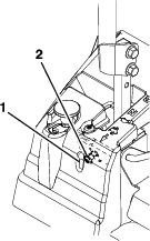
Located on either side of the machine, below the seat are the pump control linkages. Rotating the end nut with a 1/2 inch deep socket wrench allows fine tuning adjustments so that the machine does not move in neutral. Any adjustments should be made for neutral positioning only.
-
Prior to starting the engine, push the deck lift pedal and remove the height of cut pin. Lower deck to the ground.
-
Raise the rear of machine up and support with jack stands (or equivalent support) just high enough to allow drive wheels to turn freely.
-
Remove the electrical connection from the seat safety switch, located under the bottom cushion of the seat. The switch is a part of the seat assembly.
-
Temporarily install a jumper wire across the terminals in the connector of the main wiring harness.
-
Start engine. Brake must be engaged and motion control levers out to start engine. Operator does not have to be in the seat. Run engine at full throttle and release brake.
-
Run the unit at least 5 minutes with the drive levers at full forward speed to bring hydraulic oil up to operating temperature.
Note: The motion control lever needs to be in neutral while making any necessary adjustments.
-
Bring the motion control levers into the neutral position. The control plate tabs should touch the return to neutral plates on the hydros. Adjust pump control rod lengths by turning the nut in the appropriate direction until the wheels slightly creep in reverse (see Figure 74). Move the motion control levers to the reverse position and while applying slight pressure to the lever allow the reverse indicator springs to bring the levers back to neutral. The wheels must stop turning or slightly creep in reverse.
The motion control cover may need to be removed to gain access.
-
Shut off unit. Remove jumper wire from wire harness and plug connector into seat switch.
-
Remove the jack stands.
-
Raise the deck and re-install the height of cut pin.
-
Check that the machine does not creep in neutral with the park brake disengaged.
Electric Clutch Adjustment
No adjustment necessary.
Cleaning
Cleaning and Storing Safety
-
Park machine on level ground, disengage drives, set parking brake, stop engine, and remove key. Wait for all moving parts to stop before leaving the operator’s position. Allow the machine to cool before servicing, adjusting, fueling, cleaning, or storing.
-
Clean grass and debris from the cutting unit, muffler, drives, grass catcher, and engine compartment to prevent fires.
-
Allow the machine to cool before storing the machine in any enclosure. Do Not store the machine or fuel container, or refuel, where there is an open flame, spark, or pilot light such as on a water heater or other appliance.
Clean Debris From Machine
| Maintenance Service Interval | Maintenance Procedure |
|---|---|
| Before each use or daily |
|
-
Stop engine, wait for all moving parts to stop, and remove key. Engage parking brake.
-
Clean off any oil, debris, or grass build-up on the machine and cutting deck, especially under deck belt shields, around the fuel tank, around engine and exhaust area.
Important: You can wash the machine with mild detergent and water. Do not pressure wash the machine. Avoid excessive use of water, especially near the control panel, under the seat, around the engine, hydraulic pumps, and motors.
Clean Engine and Exhaust System Area
| Maintenance Service Interval | Maintenance Procedure |
|---|---|
| Before each use or daily |
|
Caution
Excessive debris around engine cooling air intake and exhaust system area can cause engine, exhaust area, and hydraulic system to overheat which can create a fire hazard.
Clean all debris from engine and exhaust system area.
-
Stop engine, wait for all moving parts to stop, and remove key. Engage parking brake.
-
Clean all debris from rotating engine air intake screen, around engine shrouding, and exhaust system area.
-
Wipe up any excessive grease or oil around the engine and exhaust system area.
Remove Engine Shrouds and Clean Cooling Fins
| Maintenance Service Interval | Maintenance Procedure |
|---|---|
| Every 100 hours |
|
-
Stop engine, wait for all moving parts to stop, and remove key. Engage parking brake.
-
Remove cooling shrouds from engine and clean cooling fins. Also clean dust, dirt and oil from external surfaces of engine which can cause inadequate cooling.
-
Make sure cooling shrouds are reinstalled. Operating the engine without cooling shrouds will cause engine damage due to overheating.
Clean Grass Build-Up Under Deck
| Maintenance Service Interval | Maintenance Procedure |
|---|---|
| Before each use or daily |
|
-
Park the machine on a level surface and disengage the blade control switch.
-
Stop engine, wait for all moving parts to stop, and remove key. Engage parking brake.
-
Raise deck to the transport (5 inch (12.7 cm) cutting height) position. Lift the front of unit and support unit using jack stands or equivalent support.
-
Clean out any grass build-up from underside of deck and in discharge deflector.
Waste Disposal
Motor Oil Disposal
Engine oil and hydraulic oil are both pollutants to the environment. Dispose of used oil at a certified recycling center or according to your state and local regulations.
Battery Disposal
Danger
Battery electrolyte contains sulfuric acid, which is poisonous and can cause severe burns. Swallowing electrolyte can be fatal or if it touches skin can cause severe burns.
-
Wear safety glasses to shield eyes, and rubber gloves to protect skin and clothing when handling electrolyte.
-
Do Not swallow electrolyte.
-
In the event of an accident, flush with water and call a doctor immediately.
Federal law states that batteries should not be placed in the garbage. Management and disposal practices must be within relevant federal, state, or local laws.
If a battery is being replaced or if the unit containing the battery is no longer operating and is being scrapped, take the battery to a local certified recycling center. If no local recycling is available return the battery to any certified battery reseller.