Note: The Brake and Signal Kit (Toro Part No. 140-4785 for the Workman GTX, 145-2082 for the Workman MDX, or 145-2296 for the Workman HDX) must be installed on the machine to install this kit.
Installation
Preparing a Machine
-
Park a machine on a level surface.
-
Engage the parking brake.
-
Shut off the engine and remove the key.
-
Disconnect the battery; refer to your Operator’s Manual.
Installing the License Plate Bracket and Wire Harness
Parts needed for this procedure:
| Wire harness | 1 |
| License plate bracket | 1 |
| License plate light | 2 |
| Hex button-head bolt (#10 x 3/4 inch) | 4 |
| Clip nut | 4 |
| Hex flange-head bolt (5/16 x 3/4 inch) | 4 |
| Cable tie | 1 |
Installing the Plate Bracket and Wire Harness
-
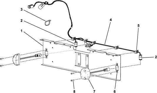
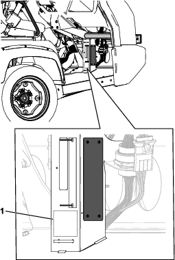
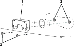
Route the license plate wire harness along the top of the license plate bracket, keeping the 2 large connectors and the fuse to the left side (Figure 1).
-
Secure the wire harness to the bracket by pushing the 4 push-in fasteners on the harness into the corresponding holes in the bracket (Figure 1).
-
Route the license plate light connectors through the large holes on either end of the bracket and connect them to the 2 license plate lights (Figure 1).
-
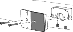
Install the lights to the bracket using 4 hex button-head bolts (#10 x 3/4 inch) and 4 clip nuts as shown in Figure 1.
-
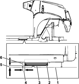
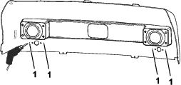
Install the bracket to your Workman as follows:
-
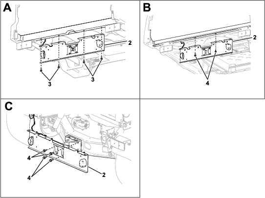
Workman GTX: Using 4 hex flange-head bolts (5/16 x 3/4 inch), install the bracket to the underside of the cargo bed (A in Figure 2).
Note: The Homologation Lamp Kit and the Brake Signal Kit are not compatible with the steel bed Workman GTX.
-
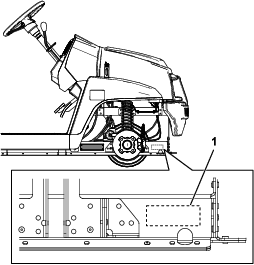
Workman MDX: Remove the 2 existing flange-head bolts from the underside of the cargo bed and use them to install the bracket (B in Figure 2).
-
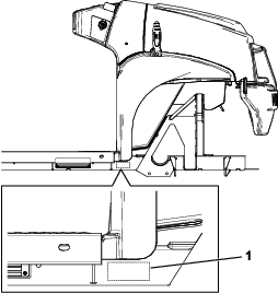
Workman HDX: Remove the 4 existing flange-head bolts from the hitch plate and use them to install the bracket (C in Figure 2).
Note: Ensure that you route the wire harness over the hitch.
-
-
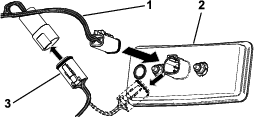
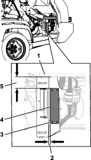
Unplug the Brake and Signal Kit wire harness from the left taillight and insert the taillight connector from this kit (Figure 3).
-
Using the other connector on the wire harness from this kit, connect it to the Brake and Signal Kit wire harness that you just unplugged (Figure 3).
-
Use the cable tie to secure the excess wire harness to the machine.
Installing the Serial Plate
Parts needed for this procedure:
| Serial plate | 1 |
| Pop rivet (3 x 10 mm) | 4 |
Installing the Serial Plate (Workman GTX)
Installing the Serial Plate (Workman MDX)
Installing the Speed Plates (GTX only)
Parts needed for this procedure:
| Plate-mount bracket | 2 |
| Speed plate (25 km/h) | 3 |
| Pop rivet (3/16 x 15/16 inch) | 17 |
Installing the Speed Plates to the Seat Base Sides
-
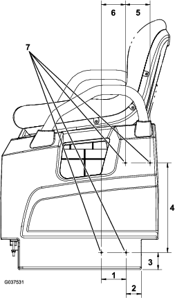
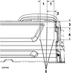
On the left side of the machine, measure 51 mm (2 inches) from bottom, left of the seat base side, and mark this location (Figure 10).
-
Measure 57 mm (2-1/4 inches) directly above the location and mark this location (Figure 10).
-
Measure 83 mm (3-1/4 inches) from the left of the location marked in step 2, and mark this location (Figure 10).
-
Measure 80 mm (3-3/16 inches) from the left of the location marked in step 3, then measure 299 mm (11-3/4 inches) directly above this location, and mark this location (Figure 10).
-
Measure 83 mm (3-1/4 inches) from the right of the location marked in step 4, and mark this location (Figure 10).
-
Drill a 5 mm (13/64 inch) hole at each of the 4 marked locations (Figure 10).
Caution
Use caution when drilling the holes into the seat base sides.
On the Workman GTX Gasoline Utility Vehicle, the fuel tank resides behind the seat base side on the driver’s side of the machine, and the battery resides behind the seat base side on the passenger’s side of the machine.
On the Workman GTX Electric Utility Vehicle, the battery charger resides behind the seat base side on the driver’s side of the machine.
On the Workman GTX Lithium Utility Vehicle, the battery charger resides behind the seat base side on the passenger’s side of the machine.
If you drill too far into the seat base sides, you may damage these components.
-
Install the plate-mount bracket to the seat base side using 4 pop rivets (3/16 x 15/16 inch) as shown in Figure 11.
-
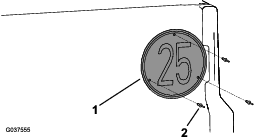
Install the speed plate to the plate-mount bracket using 3 pop rivets (3/16 x 15/16 inch) as shown in Figure 12.
-
Repeat the procedure for the right side of the machine.
Installing the Speed Plate to the Tailgate
-
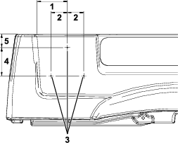
On the right side of the tailgate, measure 95 mm (3-3/4 inches) from the right edge of the tailgate and 70 mm (2-3/4 inches) from the top of the tailgate, and mark this location (Figure 13).
-
Measure 128 mm (5 inches) down from the hole marked in step 1 and 74 mm (2-7/8 inches) to the right and left and mark the 2 locations (Figure 13).
-
Drill a 5 mm (13/64 inch) hole at each of the 3 marked locations (Figure 13).
Important: Drill through only 1 wall of the tailgate.
-
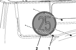
Install the speed plate to the tailgate using 3 pop rivets (3/16 x 15/16 inch) as shown in Figure 14.
Installing the Speed Plates (MDX only)
Parts needed for this procedure:
| Speed plate (25 km/h) | 3 |
| Pop rivet (3/16 x 15/16 inch) | 9 |
Installing the Speed Plates to the Cargo Bed Sides
-
On the left side of the cargo bed, measure 136 mm (5-3/8 inches) from the right edge of the molding and 60 mm (2-3/8 inches) down from the top of the cargo bed, and mark this location (Figure 15).
-
Measure 128 mm (5 inches) down from the hole marked in step 1 and 74 mm (2-7/8 inches) to the right and left mark the 2 locations (Figure 15).
-
Drill a 5 mm (13/64 inch) hole at each of the 3 marked locations (Figure 15).
Important: Drill through only 1 wall of the cargo bed.
-
Install the speed plate to the cargo bed side using 3 pop rivets (3/16 x 15/16 inch) as shown in Figure 16.
-
Repeat the procedure for the right side of the machine.
Installing the Speed Plate to the Tailgate
-
On the right side of the tailgate, measure 130 mm (5-1/8 inches) from the right edge of the tailgate and 60 mm (2-5/16 inches) from the top of the tailgate, and mark this location (Figure 17).
-
Measure 128 mm (5 inches) down from the hole marked in step 1 and 74 mm (2-7/8 inches) to the right and left mark 2 locations (Figure 17).
-
Drill a 5 mm (13/64 inch) hole at each of the 3 marked locations (Figure 17).
Important: Drill through only 1 wall of the tailgate.
-
Install the speed plate to the tailgate using 3 pop rivets (3/16 x 15/16 inch) as shown in Figure 18.
Installing the Speed Decals (HDX only)
Parts needed for this procedure:
| Speed decal (32 km/h) | 3 |
Installing the Speed Decals to the Cargo Bed Sides
-
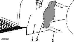
On the left side of the cargo bed, attach the speed decal to the area in between the second and third channels as shown in Figure 19.
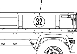
-
Repeat the procedure for the right side of the machine.
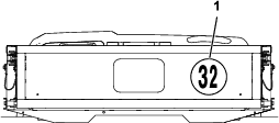
Installing the Speed Decal to the Tailgate
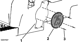
On the tailgate, attach the speed decal to the area in between the rear logo and the right channel as shown in Figure 20.
Installing the Turn Signal Light Brackets (HDX only)
Parts needed for this procedure:
| Turn signal light bracket | 2 |
| Carriage bolt (#10 x 1/2 inch) | 4 |
| Locknut (#10) | 4 |
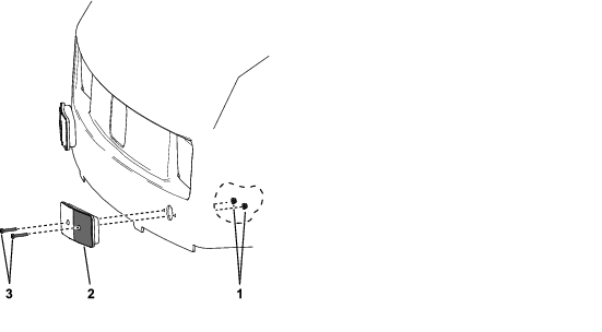
-
Remove the 4 Phillips-head bolts and nuts that secure the turn signal lights to the hood (Figure 21).
Note: Retain the removed hardware for later installation.
-
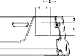
On the inside of the hood, locate the 4 dots next to the turn signal light holes and drill 6 mm (1/4 inch) diameter holes as shown in Figure 22.
-
Install the 2 turn signal brackets to the hood using 4 carriage bolts (#10 x 1/2 inch) and 4 locknuts (#10) (Figure 23).
-
Install the lights to the brackets using the hardware removed in step 1 (Figure 24).
Completing the Installation
Install the negative battery cable to the battery.
Testing the Lights
Note: Get someone to help you see the lights as you test them.
-
Sit in the operator’s seat and rotate the key to the ON position.
-
Press the light switch to the ON position.
Note: The headlights and the license plate lights should illuminate.
-
Move the turn signal to the left and right positions.
Note: The position lights should flash at the front of the machine and the taillight should flash at the back of the machine.
-
Step on the brake pedal.
Note: The brake lights should illuminate.
-
Rotate the key to the OFF position and remove the key.