3WD Kit
Reelmaster ® 3105-D or Groundsmaster® 3505-D Traction Unit

Preparing the Machine

  1. Park the machine on a level surface.
  2. Disengage the PTO (if equipped) and lower the cutting units.
  3. Engage the parking brake.
  4. Shut off the engine and remove the key.
  5. Wait for all movement to stop and allow the machine to cool.
    Warning
    Hot hydraulic fluid can cause severe burns.
    Allow the hydraulic fluid to cool before performing any maintenance to the hydraulic system.
     
  6. Relieve all pressure from the hydraulic system; refer to the Service Manual for your machine.
    Danger
    Hydraulic fluid escaping under pressure can penetrate the skin and cause injury.
    • Ensure that all hydraulic fluid hoses and lines are in good condition and that all hydraulic connections and fittings are tight before applying pressure to the hydraulic system.
    • Keep your body and hands away from pinhole leaks or nozzles that eject high-pressure hydraulic fluid.
    • Use cardboard or paper to find hydraulic leaks.
    • Safely relieve all pressure in the hydraulic system before performing any work on the hydraulic system.
    • Get immediate medical help if fluid is injected into the skin.
     
  7. Remove the hood from the machine; refer to the Operators Manual for your machine.

Lifting the Back of the Machine

  1. Lift the back of the machine; refer to the Operators Manual or Service Manual for your machine.

Removing the Rear Wheel and Hub Assembly

    Graphic
    G494218
  1. Remove and discard the 4 lug nuts 
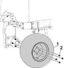
that secure the wheel to the wheel-hub assembly and remove the wheel from the machine.
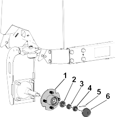
  2. Graphic
    G494230
  3. Remove and discard the dust cap , cotter pin , nut retainer , jam nut , tab washer , and wheel hub .
  4. Graphic
    G494250
  5. Remove and discard the spindle 
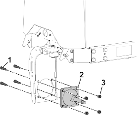
and corresponding mounting bolts and nuts .

Installing the Hydraulic Motor, Hub, and Rear Wheel

Parts Required
1
Hydraulic-motor assembly
2
Hydraulic fitting
4
Bolt (1/2 x 2-3/4 inches)
4
Locknut (1/2 inch)
1
Wheel-hub assembly
4
Lug nut
1
Locknut (1-1/2 inches)
    Graphic
    G495906
  1. Secure the hydraulic-motor assembly 
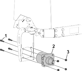
to the steering fork with 4 bolts (1/2 x 2-3/4 inches) and 4 locknuts (1/2 inch) .
  2. While holding the bolts with a backing wrench, torque the locknuts to 70 to 84 Nm (52 to 62 ft-lb).
  3. Graphic
    G495907
  4. Lubricate the o-rings on the fittings with a light coating of oil.
  5. Install the 2 hydraulic fittings on the hydraulic-motor assembly. Orient the fittings as shown. Torque the fittings 134 to 164 Nm (99 to 121 ft-lb). Use a backing wrench to retain proper orientation of the fittings while torquing them.
  6. Graphic
    G495908
  7. Slide the wheel hub 
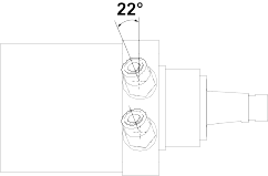
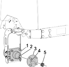
on the hydraulic-motor assembly . Ensure that the groove in the hub is aligned with the key on the motor.
  8. Install the hub locknut (1-1/2 inches) until it is lightly seated against the hub.
  9. Graphic
    G494330
  10. Install the previously removed rear wheel assembly 
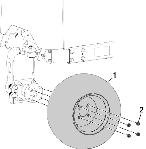
to the wheel hub by lightly seating the 4 lug nuts against the wheel.
  11. Lower the machine to the ground. Chock on the back tire to prevent the machine from rolling.
  12. Torque the lug nuts in a crossing pattern to 61 to 88 Nm (45 to 65 ft-lb).
  13. Torque the hub locknut (1-1/2 inches) to 339 to 373 Nm (250 to 275 ft-lb).

Removing the Hydraulic Hose

  1. Remove and discard the existing upper hydraulic hose routed between the piston pump and the upper front hydraulic tube .
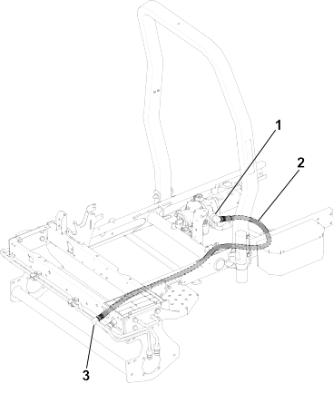
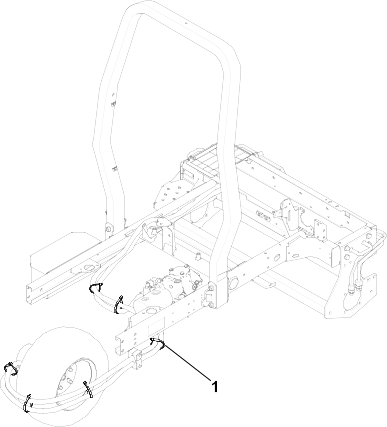
    Graphic
    G494354

Installing the Hydraulic Hoses

Parts Required
1
Hydraulic hose (70 inches)
1
Hydraulic hose (129 inches)
2
Clamp
1
Clamp case
2
Bolt (5/16 x 2-3/4 inches)
2
Locknut (5/16 inch)
6
Cable tie
Note: Before installing any hydraulic hoses, ensure that the correct O-rings are in position and lubricated with hydraulic fluid.
  1. Connect the straight end of the hydraulic hose (70 inches) to the lower hydraulic fitting on the hydraulic-motor assembly. Route the other end of the hose to the piston pump and connect it to the open fitting on the pump.
  2. Connect one end of the hydraulic hose (129 inches) to the upper fitting on the hydraulic-motor assembly. Route the other end of the hose to the upper front hydraulic tube and connect it to the open fitting on the tube.
    Graphic
    G494581
  3. On the rear frame tab on the machine, install the 2 hose clamps 
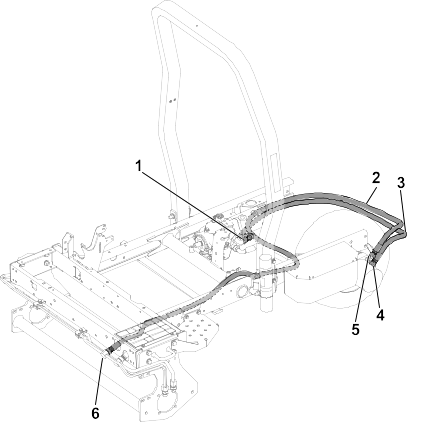
and clamp case using 2 bolts (5/16 x 2-3/4 inches) and 2 locknuts (5/16 inch) . Ensure that the hydraulic hoses are routed between the hose clamps as shown.
    Graphic
    G494604
  4. Secure the hydraulic hoses with 6 cables ties 
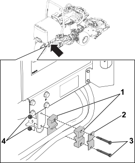
. Refer to the following figure for the appropriate cable tie locations.
    Graphic
    G494633