Installation
Preparing the Machine
-
Park the machine on a level surface.
-
Lower the loader arms.
-
Shut off the engine and remove the key.
-
Open the hood and secure it with the prop rod.
Removing the Fuse Panel
-
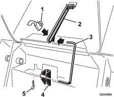
Pull the hairpin cotter from the bottom end of the hood prop-rod and slide the prop rod out of the retaining brackets and the prop-rod tab.
-
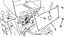
Remove the 4 screws securing the fuse panel and then pull the panel out and up to remove it.
Removing the Existing USB Socket
-
Remove the 4 screws (1/4 inch) securing the control plate to the main frame.
-
Move the control plate out of the frame.
-
Remove the black and white wires secured to the USB connector.
-
Loosen the retainer nut and remove the USB socket from the control plate.
Installing the 12V Receptacle
Warning
Using a drill without proper eye protection may allow debris to enter the eye, causing injury.
When drilling or carrying out other operation, always wear eye protection.
-
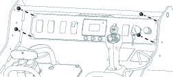
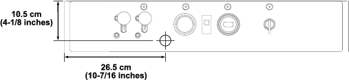
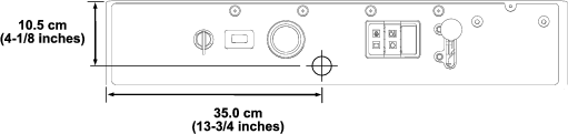
TX 427 and TX 525 machines only: Mark and drill a hole (1-5/32 inch diameter) into the control in the location shown below.
Note: If you do not have a 1-5/32 inch drill bit, use a 1-1/8 inch drill bit to drill the hole and then grind the hole to expand it.
-
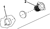
Remove the locking ring from the 12V receptacle.
-
Install the 12V receptacle in the hole and secure it with the locking ring.
Installing the Wire Harnesses
Parts needed for this procedure:
| Electric accessory port | 1 |
| Splitter wire harness | 1 |
| Wire harness kit (TX 1300 only) | 1 |
-
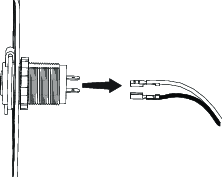
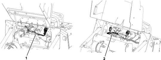
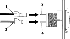
Install the post connectors from the port wire harness to the posts on the 12V receptacle.
-
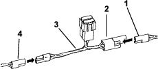
Connect the port wire harness to an outgoing power connector (end with 2 connectors) of the splitter harness.
-
Connect the other end of the splitter harness to an accessory connector on the machine wire harness.
Note: If no connectors are open on the machine wire harness, unplug an accessory from the machine wire harness and plug it into the other outgoing power connector of the splitter harness.
-
TX 525 machine only: Install the fuse panel.
Note: Reverse the procedure for Removing the Fuse Panel.
-
TX 1300 machine only: Install the control plate and secure it with the 4 screws (1/4 inch).
-
Close the hood.
-
TX 1300 machine only: Connect the new wire harness kit to the snowthower and the wire harness coming from the control box. Refer to the snowthower Operator’s Manual.