Warning
CALIFORNIA
Proposition 65 Warning
Use of this product may cause exposure to chemicals known to the State of California to cause cancer, birth defects, or other reproductive harm.
Installation
Preparing the Machine
-
Park the machine on a level surface.
-
Engage the parking brake.
-
Shut off the engine and remove the key.
Removing the Cutting Units from the Machine
-
Disconnect the cutting unit power disconnect couplers; refer to your machine Operator’s Manual.
-
Remove the grass baskets (if equipped) and cutting units from the machine; refer to your machine Operator’s Manual.
Installing the Weights
Parts needed for this procedure:
| TMD weight | 3 |
| Mount plate | 3 |
| Rubber damper mount | 9 |
| Grommet | 3 |
| Splined press bolt | 3 |
| Nut (5/16 inch) | 18 |
| Nut (5/8 inch) | 3 |
Repeat this procedure for each cutting unit.
-
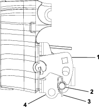
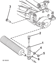
Perform the following steps to remove tension from the suspension counterbalance assembly. Refer to Figure 1.
-
Remove the cotter pin from the clevis pin that secures the tensioner arm.
-
Insert a 0.95 cm (3/8 inch) drive breaker bar into the square drive hole of the tensioner arm.
Note: Slightly pull up on the breaker bar to remove the torsion spring tension on the clevis pin.
-
Remove the clevis pin and allow the counterbalance springs to relax.
-
-
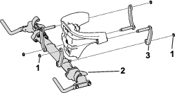
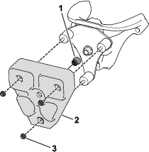
Remove the crossarm assembly by loosening and removing the nuts that secure the link assembly arms to the steering head (Figure 2).
-
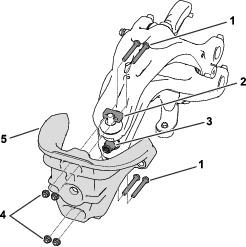
Remove the hex-head bolts (5/16 x 2-1/2), nuts (5/16 inch), and clamps that secure the steering head to the suspension (Figure 3).
Note: Retain the hardware for installation.
-
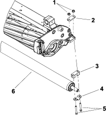
Remove the plastic splined grommet from the steering head (Figure 3).
-
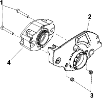
Use an arbor press to install a splined press bolt into the steering head hole that was left by removing the grommet.
-
Use the hardware that you removed in step 3 to install the steering head to the suspension (Figure 3).
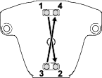
Torque the hex-head bolts (5/16 x 2-1/2) to 19 to 24 ft-lb (26 to 33 N∙m) in the order shown in Figure 4
-
Install the crossarm assembly to the steering head (Figure 2).
-
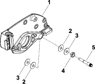
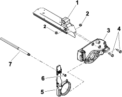
Use a nut (5/8 inch) to secure the mount plate to the steering head (Figure 5).
Note: Ensure that the top profile of the mounting plate is aligned with the ledge profile of the steering-head casting.
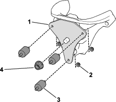
-
Secure 3 rubber damper mounts to the mount plate with 3 nuts (5/16 inch) as shown in Figure 5.
Note: Replace the rubber damper mounts annually.
-
Insert a grommet into the TMD weight (Figure 6).
-
Use 3 rubber damper mounts and 3 nuts (5/16 inch) to secure the TMD weight to the mount plate (Figure 6).
-
Insert a 0.95 cm (3/8 inch) drive breaker bar into the square drive hole of the tensioner arm.
-
Use the previously removed cotter pin to secure the clevis pin into the middle holes in the counterbalance mount and below the tensioner arm; refer to Figure 1 for the correct location of the clevis pin.
Note: The tensioner arm can be rotated with a breaker bar or ratchet wrench (0.95 cm or 3/8 inch drive) to align the holes.
Note: For hydraulic reel machines, return the counterbalance assembly to the electric reel machine configuration as shown in Figure 1. This position counters the added weight of the TMD.
Installing the Pitch Arms to the Cutting Units
Parts needed for this procedure:
| Pitch arm | 6 |
Preparing the Cutting Unit for Installation
Perform this procedure for each cutting unit. Retain all hardware for installation in Installing the Pitch Arm to the Side Plate
-
Remove the weight from the right side plate by removing the cap screws and hex nuts that secure the weight to the right side plate.
-
If the cutting unit is equipped with an optional groomer or rear roller brush, remove the drive components for those options from the cutting unit.
-
Loosen the locknuts on each bedbar pivot bolt and remove the bedbar pivot bolts, metal washers, and plastic washers from the side plates (Figure 8).
Note: Observe the location of plastic and steel washers for assembly purposes.
-
Perform the following steps to remove the rear roller assembly. Refer to Figure 9.
-
Loosen the 2 flange nuts that secure the rear roller shaft to each rear roller bracket.
-
Perform the following step on one of the rear roller brackets.
Note: On cutting units equipped with the optional High Height-of-Cut Kit, there will be additional roller shims installed between rear roller bracket and cutting unit side plate.
-
Note quantity and location of roller shims for assembly purposes.
-
Remove flange nuts and socket head screws that secure shaft retainer, roller height spacer and roller shims to the cutting unit side plate.
-
Remove the roller bracket and roller shims from the rear roller and cutting unit.
-
-
-
Perform the following steps to remove the front roller assembly. Refer to Figure 10.
-
Loosen the cap screw that secures the front roller shaft to each front height-of-cut arm.
-
On one of the height-of-cut arms, remove the HOC nut, HOC washer, and plowbolt that secure the HOC arm to the cutting unit side plate. Remove the HOC arm from the cutting unit.
-
Slide the front roller assembly from the remaining HOC arm on the cutting unit.
-
-
Remove the crosslink by removing the washer-head screws that secure the crosslink to the pitch arms (Figure 11).
-
Ensure that the cutting reel is supported to keep it from shifting or falling.
-
Remove the shoulder bolts and flange nuts that secure the side plate to the cutting unit crossmember (Figure 11).
-
Remove the side plate from the reel shaft, rollers, bedbar, and cutting unit crossmember (Figure 11).
-
Remove the existing pitch arm from the side plate (Figure 11).
Installing the Pitch Arm to the Side Plate
-
Thoroughly clean the side plates and other cutting unit components. Inspect the side plates for wear or damage and replace the components if needed.
-
Carefully slide the side plate with the new pitch arm onto the cutting reel assembly (Figure 12).
Important: Ensure that the side plate is fully seated onto the bearing on the reel shaft.
-
Install the shoulder bolts and flange nuts to secure the side plate to the crossmember (Figure 12).
-
Torque the shoulder bolts to 210 to 240 in-lbs (24 to 27 N∙m).
-
Position the crosslink to the pitch arms and secure with 2 washer-head screws (Figure 12).
-
Apply antiseize lubricant to the bedbar threads and the shoulder area of each bedbar pivot bolt.
-
Slide a metal washer and then a plastic washer onto each bedbar pivot bolt (Figure 13).
-
Position a metal washer and a plastic washer between the bedbar and each cutting unit side plate (Figure 13).
-
Install the bedbar pivot bolt assemblies (Figure 13).
Note: Ensure that the plastic washers are not caught on the threads of the pivot bolts.
-
Torque each bedbar pivot bolt from 190 to 240 in-lbs (22 to 27 N∙m).
-
Tighten both locknuts until the outside washers do not have any endplay, but can still be rotated.
Important: Do not overtighten the locknuts. Overtightening distorts the side plates and affects the reel bearing adjustment. When the locknut is correctly tightened, there may be a gap at the inside washers.
-
Perform the following step to install the front roller assembly to the cutting unit; refer to Figure 14.
-
Slide the front roller shaft into the HOC arm that is attached to the cutting unit.
-
Inspect the condition of the HOC screw. If necessary, apply antiseize lubricant to the threads of the HOC screw. Thread the HOC screw into the HOC arm.
Note: Ensure that the ring on the HOC screw fits into the notch on the side plate.
-
Secure the HOC arm to the side plate with a plow bolt, HOC washer, and HOC nut.
Note: The tab on the HOC washer should be positioned into the HOC arm slot and orientated down toward the roller.
-
Use the cap screw to secure the front roller to the HOC arm.
Note: Ensure that the front roller is centered to the cutting reel.
-
-
Perform the following steps to install the rear roller assembly to the cutting unit; refer to Figure 15.
-
Slide the rear roller shaft into the rear roller bracket attached to the cutting unit.
-
Secure the second roller bracket and shims to the side plate with 2 carriage screws and 2 flange nuts. Do not fully tighten flange nuts.
-
Center the rear roller to the cutting reel and secure the roller in place by tightening the flange nuts.
-
-
Adjust the cutting unit; refer to the cutting unit Operator’s Manual.
Note: The parallel position of the rear roller to the cutting reel is controlled by the precision-machined crossmember and side plates of the cutting unit. If necessary, you can loosen the cutting unit side plates and make a slight adjustment to align the rear roller with the cutting reel so that they are parallel.
-
Use the cap screws and hex nuts to secure the weight to the right side plate (Figure 16).
-
If the cutting unit is equipped with an optional groomer or rear roller brush, install the components for those options to the cutting unit. Refer to the Installation Instructions for each kit as necessary.
Trimming the Grass Basket and Support Plate
Trimming the Grass Basket
You must trim the grass baskets and support plates for use with the Anti-Bobbing Kit. Perform these procedures if you use the grass baskets during operation.
-
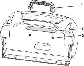
Using the installed basket handle as a template, mark a parallel line adjacent with the front face of the handle (Figure 17).
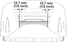
-
Measure 12.7 mm (1/2 inch) from each side of the handle and mark 2 lines that are perpendicular to the line that you made in step 1 (Figure 17).
-
Remove the handle components (handle, support plate, and nuts) from the basket (Figure 18).
-
Use the marked lines to trim out the shaded area as shown in Figure 17.
Note: Discard the trimmed material.
Trimming the Support Plate
-
With the support plate removed, trim 1.3 cm (1/2 inch) back from the front face and remove the shaded area as shown in Figure 19.

-
Use the previously removed nuts to install the handle and support plate to the grass basket (Figure 18).
Note: Ensure that the trimmed face is pointed towards the front of the basket.
-
Torque the nuts to 50 to 70 in-lb (6 to 8 N∙m).
Installing the Cutting Units to the Machine
-
Install the cutting units and grass baskets (optional) to the machine; refer to your machine Operator’s Manual.
-
Connect the cutting unit power disconnect couplers; refer to your machine Operator’s Manual.
Evaluating the Height of Cut
Due to the weight added to the suspension, the after-cut appearance results in a lower height of cut. Evaluate the height of cut for each cutting unit and adjust as needed; refer to your cutting unit Operator’s Manual.
Note: If you change the counterbalance configuration from the hydraulic setting to the electric setting, the height-of-cut difference is minimal.