Maintenance
Checking the Seat Belt
| Maintenance Service Interval | Maintenance Procedure |
|---|---|
| Before each use or daily |
|
Inspect the seat belt for wear, cuts, and proper operation of the retractor and buckle. Replace the seat belt if it is damaged.
The ROPS is an integral and effective safety device. Do not remove or alter the ROPS.
There is no rollover protection when the roll bar is down.
Keep the roll bar in the fully raised and locked position and always wear your seat belt whenever the roll bar is up.
Ensure that the seat belt can be released quickly in the event of an emergency.
Lower the roll bar only when absolutely necessary. Do not wear the seat belt when the roll bar is down.
Raise the roll bar as soon as clearance permits.
Wheels dropping over edges, ditches, steep banks, or water can cause rollovers, which may result in serious injury or death.
Check carefully for overhead clearances before driving under any objects and do not contact them.
In the event of a rollover, take the machine to an Authorized Service Dealer and have the ROPS inspected.
Replace damaged ROPS components. Do not repair or alter them.
Use only accessories and attachments installed on the ROPS that are approved by Toro.
 |
Safety decals and instructions are easily visible to the operator and are located near any area of potential danger. Replace any decal that is damaged or missing. |
Park the machine on a level surface.
Disengage the blade-control switch.
Move the motion-control levers outward to the NEUTRAL-LOCK position.
Shut off the machine and remove the key.
Wait for all moving parts to stop.
Turn the battery-disconnect switch to the OFF position.
Remove the locknut (5/16 inch) securing the rear of the seat pan to the frame.
With assistance and seat-support bolts in place, rotate the seat toward the front of the machine.
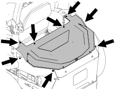
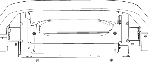
Remove the 8 torx-head screws securing the rear cover to the machine.
Remove the rear cover.
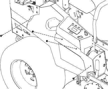
Remove the 2 torx-head bolts (5/16 inch) securing the cover plate to the frame.
Remove the 4 torx-head shoulder bolts (1/4 x 1/2 inch) securing the right pod to the frame.
Remove the right pod.
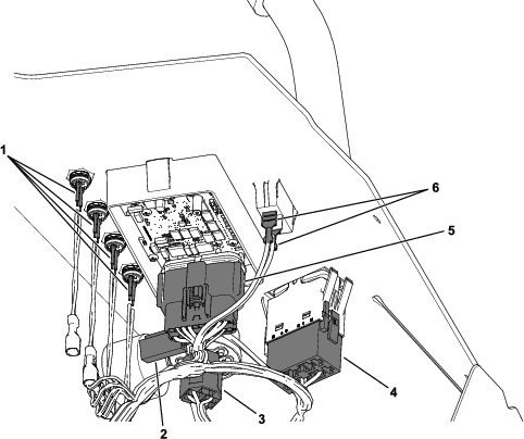
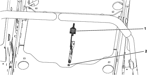
Remove the 2 locknuts (5/16 inch) and carriage bolts securing the electrical-cover plate to the chassis.
Remove the electrical-cover plate.
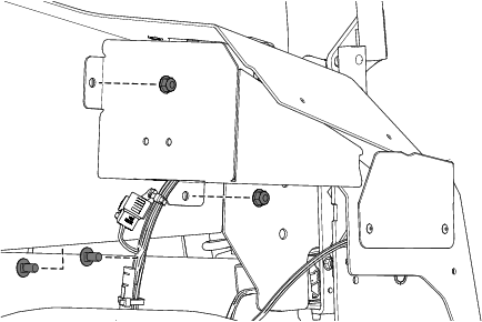
Disconnect the main harness from the following:
Light switch
Display
4 buttons
PTO switch
Key switch
Audible alarm
Remove the 2 locknuts (5/16 inch) and carriage bolts securing the right console to the frame.
Remove the right console.
Remove the 4 torx-head shoulder bolts (1/4 x 1/2 inch) securing the left pod to the frame.
Remove the left pod.
Remove the 2 locknuts (5/16 inch) and carriage bolts securing the left console to the frame.
If applicable, disconnect the USB port.
Cut the cable tie securing the USB harness to the console.
Remove the left console.
Retain all the removed parts for later installation.
Ensure that the roll bar is in the fully-raised position.
For non-MyRide machines, remove the 2 locknuts (5/16 inch) securing the rear of the seat pan.
For non-MyRide machines, with assistance, rotate the seat assembly toward the front of the machine.
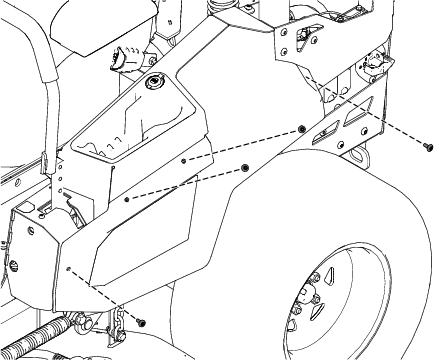
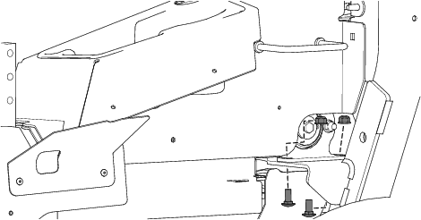
Remove the 4 torx-head bolts (5/16 x 2-3/4 inches), 4 locknuts (5/16 inch), and 4 button-head bolts (5/16 x 3/4 inch) securing the rear guards.
For machines with MyRide™ Suspension System, do the following to remove the seat assembly:
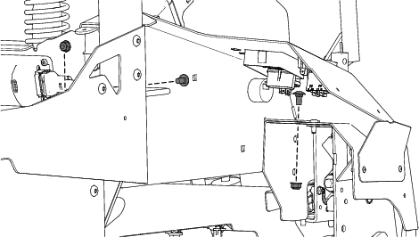
Remove the 2 locknuts (1/2 inch) from the rear shock assemblies.
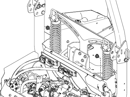
Remove the 4 carriage bolts (5/16 x 3/4 inch) and 4 locknuts (5/16 inch) securing the right and left bearing brackets to the ROPS assembly.
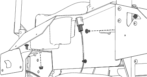
Disconnect the seat switch from the harness.
After removing the push-mount fastener, mark the location for later installation.
Using a lifting device, remove the platform and seat assembly.
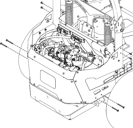
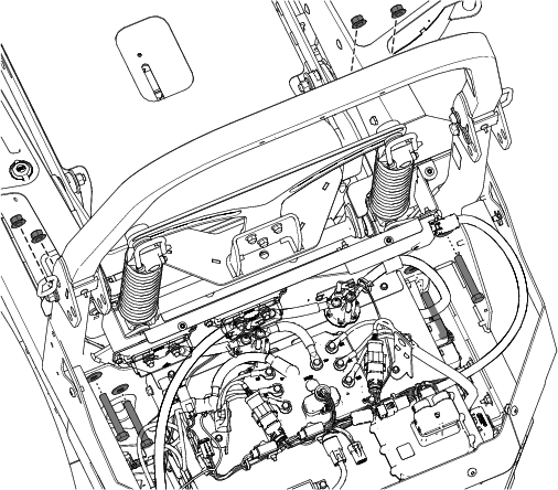
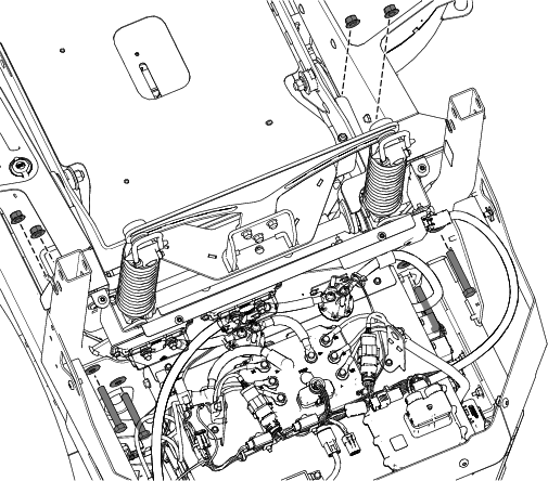
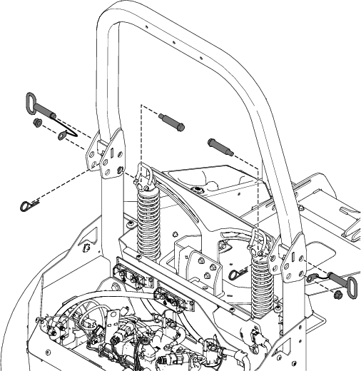
Remove the 4 hex-head bolts (1/2 x 3-1/4 inches), 4 spring washers, and 4 locknuts (1/2 inch) securing the ROPS assembly to the frame.
Using an appropriate lifting device, remove the ROPS assembly.
Failure to support the ROPS before removing the bolts may result in personal injury.
Properly secure the ROPS before performing this service step.
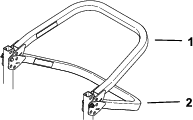
Parts needed for this procedure:
| Upper roll bar assembly | 1 |
| Lower roll bar assembly | 1 |
| Wave washer | 2 |
| Shoulder bolt | 2 |
| Locknut (1/2 inch) | 6 |
| Bumper | 2 |
| Spring washer | 4 |
| Hex-head bolt (1/2 x 3-1/4 inches) | 4 |
| Fold-pin assembly | 2 |
Loosely secure the lower roll bar assembly using 4 hex-head bolts (1/2 x 3-1/4 inches), 4 spring washers, and 4 locknuts (1/2 inch).
Note: Ensure that the plate that is welded onto the lower section of lower roll bar assemblies faces away from the frame assembly.
Secure the 2 bumpers to the upper roll bar assembly.
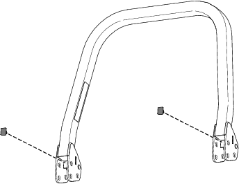
Secure the lower roll bar assemblies to the upper roll bar assembly using the 2 shoulder bolts, 2 spring washers, 2 locknuts (1/2 inch), and fold-pin assembly.
For machines with MyRide™ Suspension System, do the following to install the seat assembly:
Connect the seat switch and secure it using a new push-mount fastener.
Using a lifting device, place the platform and seat assembly on the machine.
Secure the seat to the right and left bearing brackets using the previously-removed 4 carriage bolts (5/16 x 3/4 inch) and 4 locknuts (5/16 inch).
Loosely secure the previously-removed 2 locknuts (1/2 inch) to the rear shock assemblies.
Torque the 2 shoulder bolts to 122 to 136 N∙m (90 to 100 ft-lb).
Torque the 4 hex-head bolts (1/2 x 3-1/4 inches) on the lower roll bar assemblies to 136 to 149 N∙m (100 to 110 ft-lb).
For machines with MyRide™ Suspension System only:
Torque the 2 locknuts (1/2 inch) on the rear shock assemblies to 110 to 134 N∙m (81 to 99 ft-lb).
Refer to Removing the Right Console for figure references.
Place the right console onto the frame.
Secure the right console to the frame using the previously-removed 2 locknuts (5/16 inch) and carriage bolts.
Torque the locknuts to 1,163 to 1,435 N∙cm (100 to 130 in-lb).
Connect the following to the main harness:
Light switch
Display
4 buttons
PTO switch
Key switch
Audible alarm
Secure the electrical-cover plate to the chassis using the previously-removed 2 locknuts (5/16 inch) and carriage bolts.
Secure the right pod to the frame using the previously-removed 4 torx-head shoulder bolts (1/4 x 1/2 inch).
Refer to Removing the Left Console for figure references.
Place the left console onto the frame.
If applicable, connect the USB harness to the console and secure it using a cable tie.
Secure the left console to the frame using the previously-removed 2 locknuts (5/16 inch) and carriage bolts.
Torque the locknuts to 1,163 to 1,435 N∙cm (100 to 130 in-lb).
Secure the rear cover using the previously-removed 8 torx-head screws.
Secure the left pod using the previously-removed 4 torx-head shoulder bolts (1/4 x 1/2 inch).
Refer to Removing the Rear Cover and Cover Plate and Removing the Existing Rollover Protection System (ROPS) for figure references.
Secure the cover plate to the frame using the previously-removed 2 torx-head bolts (5/16 inch).
Secure the rear cover using the previously-removed 8 torx-head screws.
Rotate the seat assembly to the operating position.
Secure the seat assembly to the seat pan using the previously-removed 2 locknuts (5/16 inch).
Torque the locknuts (5/16 inch) to 1,163 to 1,435 N∙cm (100 to 130 in-lb).
Turn the battery-disconnect switch to the ON position.
To avoid injury or death from rollover, keep the roll bar in the fully raised, locked position and use the seat belt.
Ensure that the seat is secured to the machine.
There is no rollover protection when the roll bar is in the down position.
Lower the roll bar only when absolutely necessary.
Do not wear the seat belt when the roll bar is in the down position.
Drive slowly and carefully.
Raise the roll bar as soon as clearance permits.
Check carefully for overhead clearances (i.e., branches, doorways, electrical wires) before driving under any objects and do not contact them.
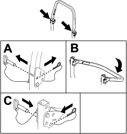
Important: Lower the roll bar only when absolutely necessary.
For both sides of the roll bar, remove the hairpin cotter and pin.
Lower the roll bar to the down position.
Note: There are 2 down positions, as shown in Figure 18.
Install the 2 pins and secure them with the hairpin cotters.
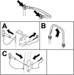
Important: Always use the seat belt with the roll bar in the raised position.
Remove the hairpin cotters and remove the 2 pins.
Raise the roll bar to the upright position.
Install the 2 pins, and secure them with the hairpin cotters.
| Maintenance Service Interval | Maintenance Procedure |
|---|---|
| Before each use or daily |
|
Inspect the seat belt for wear, cuts, and proper operation of the retractor and buckle. Replace the seat belt if it is damaged.