-
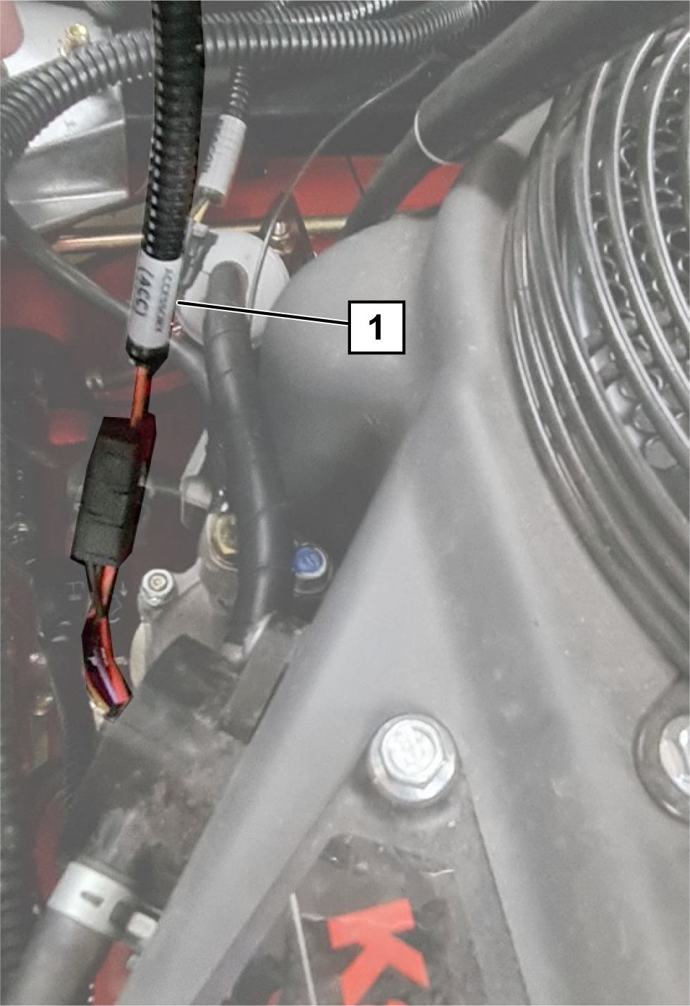
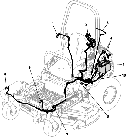
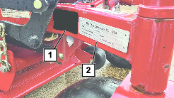
Locate the 2 pin connector on the positive battery
lead of the machine and connect the power adapter wire harness (the
connector marked, ACCESSORY ACC); refer
to Figure 8.
Note: The power adapter wire harness is the smaller harness supplied.
-
Lay the power adapter wire harness and battery connectors
near (but unable to touch) the battery terminals (Figure 9). Do not
connect the harness to the battery.
Note: Route the small power adapter harness following the positive
battery lead from the battery. Any excess cable length can be gathered
and secured beneath the battery.
-
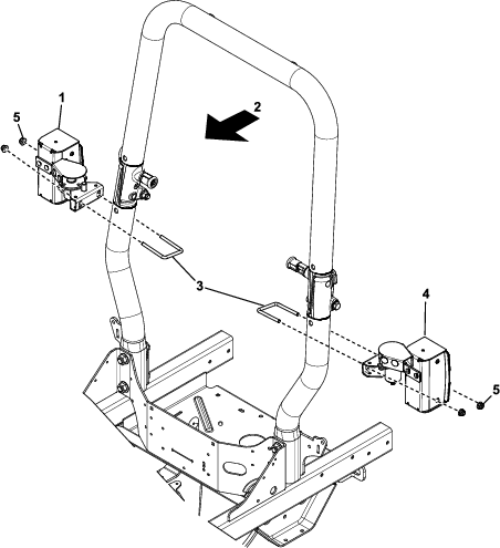
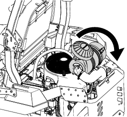
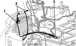
Route the large light kit wire harness by starting
from the control panel.
-
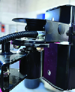
Route the harness down and along the engine side of
the MyRide pivot bar to the left side of the MyRide seat frame (Figure 10).
Note: Allow enough slack in the harness to allow flex when the seat
frame moves up and down. Secure it away from moving parts.
-
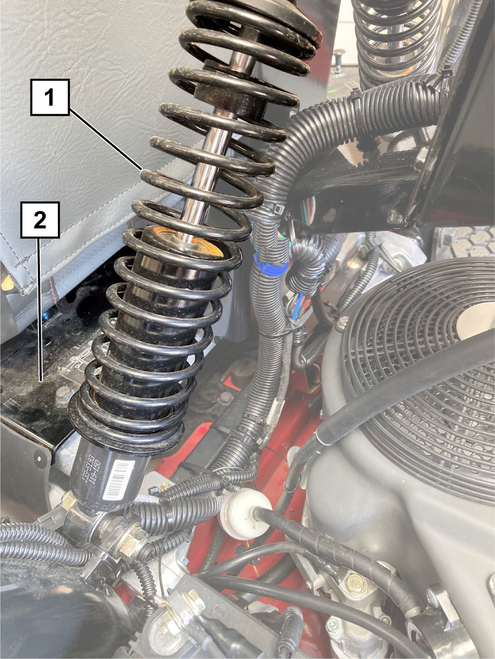
Route the harness along the left side of the MyRide
seat frame and secure the harness with edge clips attached to the
side panels (Figure 11 and Figure 12).
-
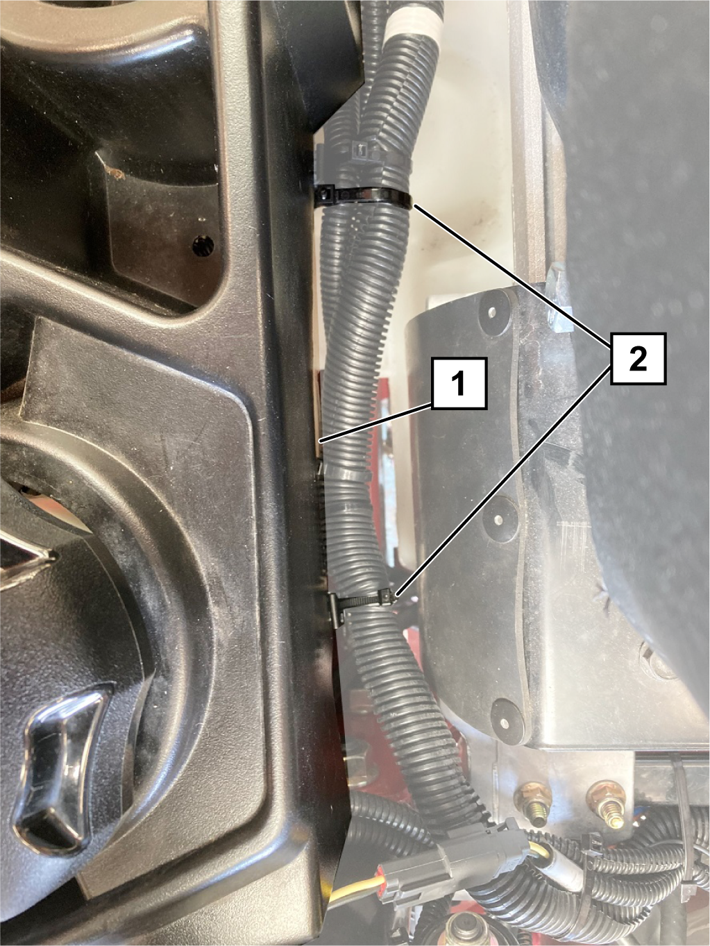
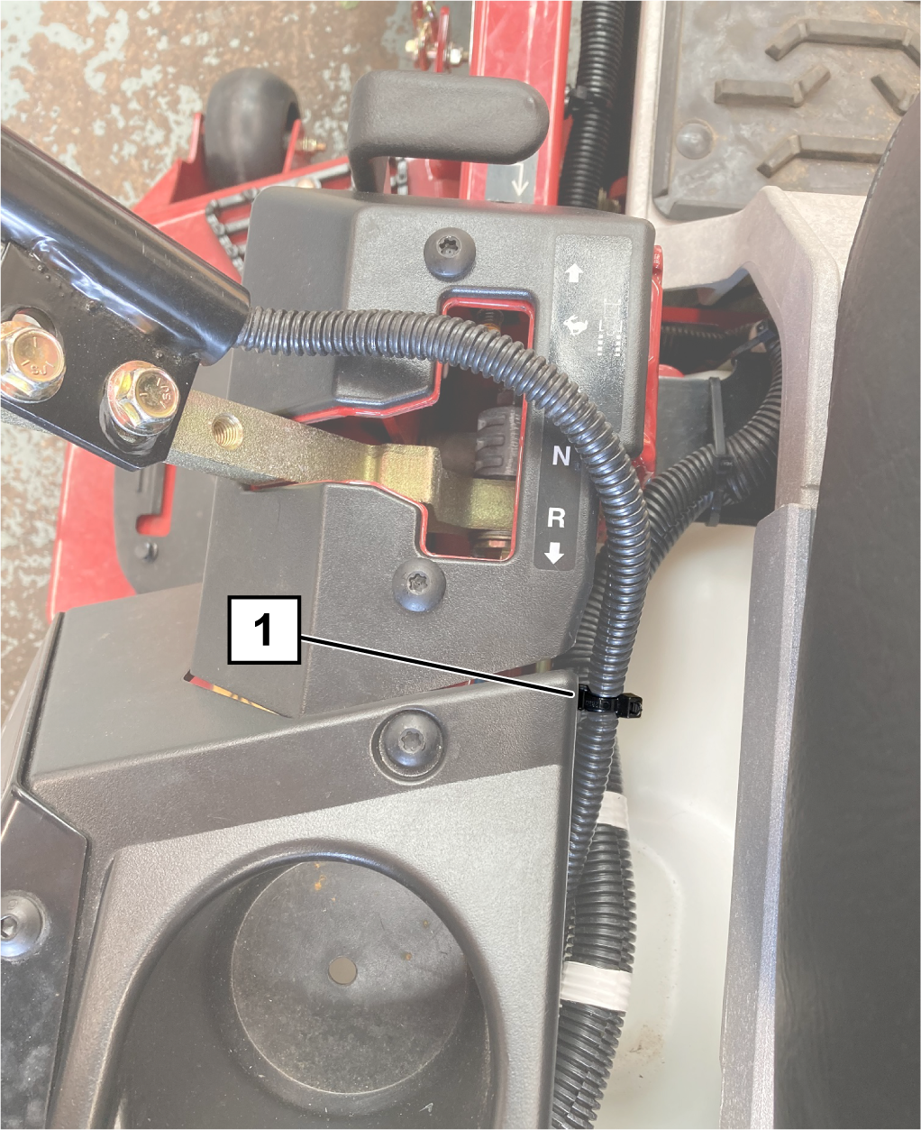
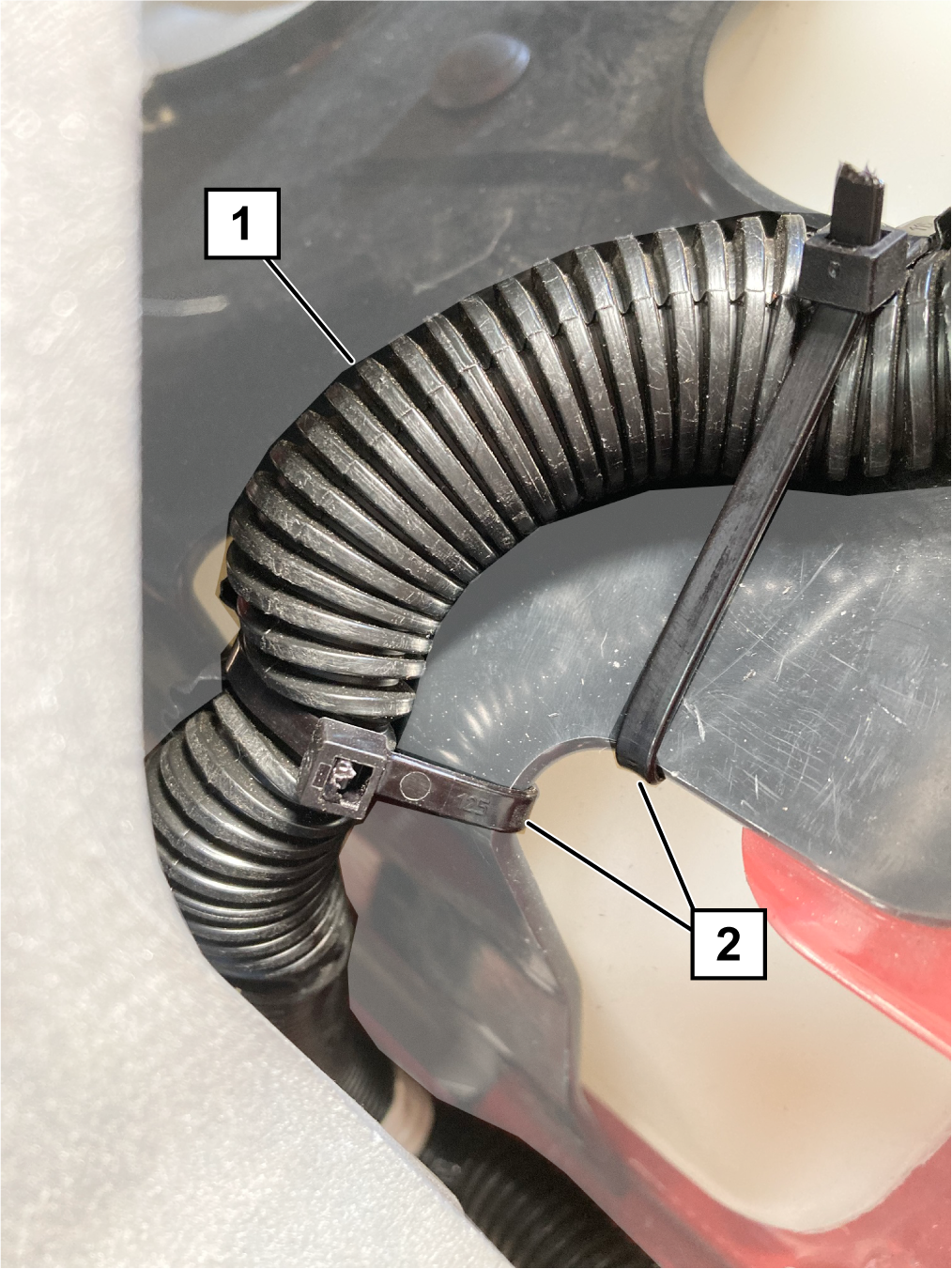
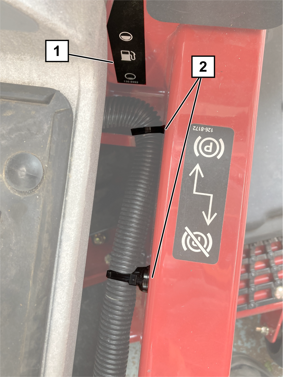
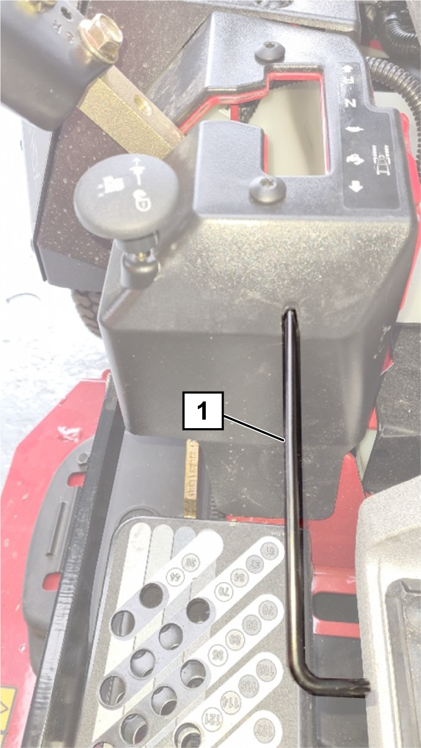
Route the harness under the seat frame toward the
mower deck along the fuel level decal (Figure 13 and Figure 14).
-
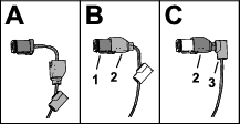
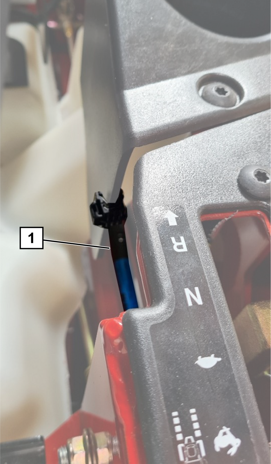
Locate the 2 front light connectors and remove both
parts of the 90° backshell from each connector (Figure 15).
Note: Retain the backshells.
-
Identify and mark the left and right front light connectors.
The right connector has blue, yellow, grey, and black wires. The left
connector has brown, yellow, grey, and black wires.
-
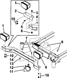
Route the two front light connectors to the correct
front light (Figure 20).
-
Route the two front light connectors through the hole
in the centre of the front light bracket, and to each front light.
-
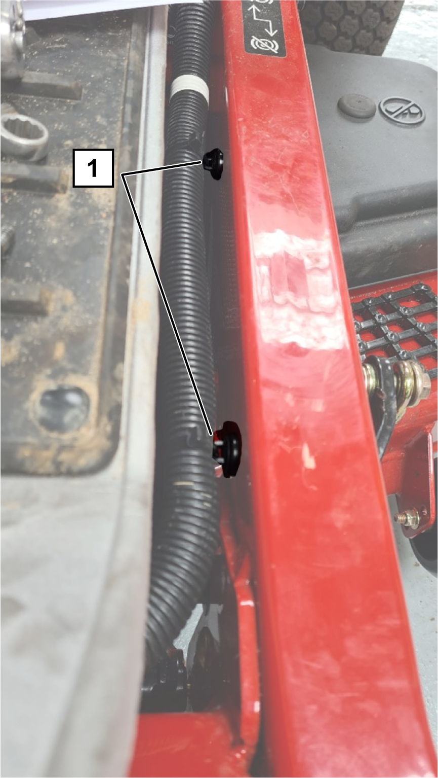
Install 2 anchors to the inside of the left chassis
rail below the operator platform (Figure 16).
-
Install the harness clip edge, to the left plastic
side of the operator platform (Figure 17).
-
Layout the wiring harness connections to their approximate
positions at the rear of the machine (Figure 20).
-
Connect the control lever connector to the light kit
wire harness (Figure 20).
-
Connect the 3 pin accessory connector to the accessory
(ACC) connector of the power adaptor harness installed earlier (Figure 9).
-
Connect the beacon wire harness to the beacon connector
of the light kit wire harness.
-
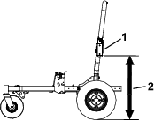
Route the left-rear light connector up the front of
the roll bar frame next to the beacon wire harness. Push connector
through the rear light mount and connect to a rear light with 2 screws
(#10 x 1-1/4 inches); refer to Figure 18.
-
Adjust the light until it is 95 cm (37-1/2 inches)
from the ground.
-
Repeat steps 11 and 12 for the right-rear light.
-
Use cable ties to secure the wires for the rear lights
and beacon harness to the roll bar.
-
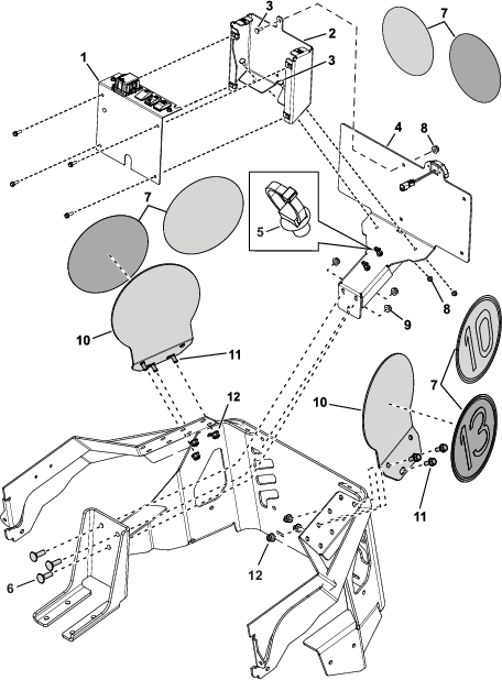
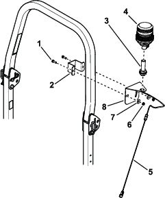
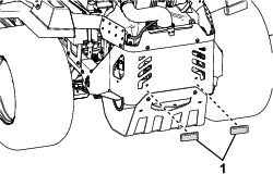
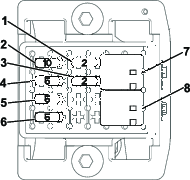
Remove the fuse box cover and install the fuse box
to the control panel with 2 button head screws (M6 x 12 mm); refer
to Figure 4.
-
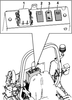
Connect the light kit wire harness to each switch,
to the flasher unit, and to the licence plate light.
-
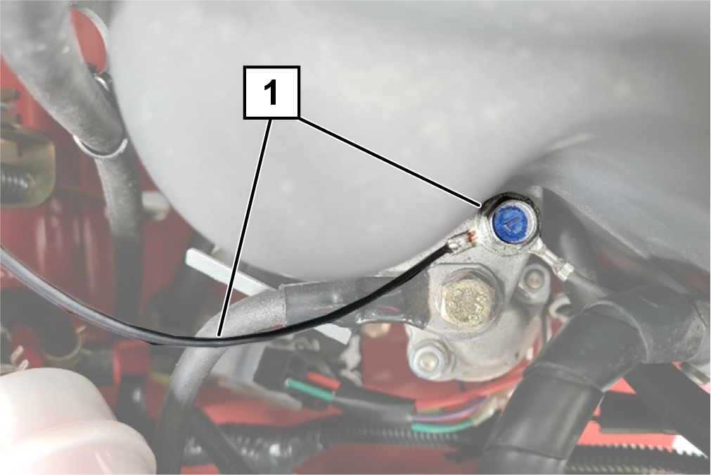
Connect the single black wire from the light kit wire
harness to the ground on top of the engine (Figure 19).
Note: Use the inner connection.
-
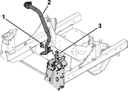
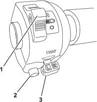
Connect the horn (Figure 3).
-
Connect the positive battery cable and positive ring
terminal from the power adaptor harness.
-
Connect the negative battery cable and negative ring
terminal from the power adaptor harness.
-
Secure all the wires and harnesses away from moving
parts and hot parts with cable ties.