Maintenance
-
Periodically check that all lights are working.
-
Ensure that the headlights are adjusted correctly.
-
Clean the lights daily.
-
Keep the lenses clean by wiping them with a damp cloth. Do not use solvent-based cleaners.
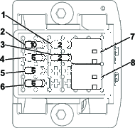
Fuses
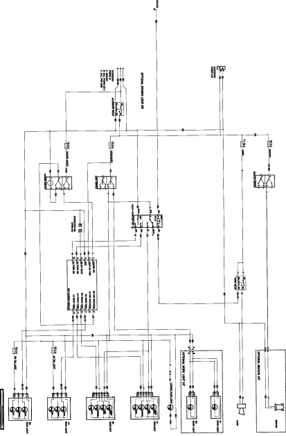
Schematic
 |
Safety decals and instructions are easily visible to the operator and are located near any area of potential danger. Replace any decal that is damaged or missing. |

Note: Determine the left and right sides of the machine from the normal operating position.
Park the machine on a level surface.
Engage the parking brake, disengage the blade-control switch (PTO), and move the motion-control levers outward to the NEUTRAL-LOCK position.
Shut off the engine and remove the key.
Allow the engine to cool.
Disconnect the negative (-) battery cable from the battery.
Disconnect the positive (+) battery cable from the battery.
Remove the floorpan.
Raise the seat.
Ensure that the ROPS is raised in the upright position.
Parts needed for this procedure:
| Right rear light assembly | 1 |
| Right light bracket | 1 |
| Left rear light assembly | 1 |
| Left light bracket | 1 |
| Flange bolt (3/8 x 3 inches) | 4 |
| Flange nut (3/8 inch) | 4 |
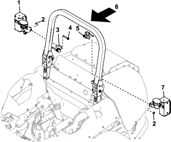
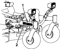
Loosely install the right rear light assembly to the right side of the roll bar frame with the right light bracket, 2 flange bolts (3/8 x 3 inches), and 2 flange nuts (3/8 inch); refer to Figure 1.
Loosely install the left rear light assembly to the left side of the roll bar frame with the left light bracket, 2 flange bolts (3/8 x 3 inches), and 2 flange nuts (3/8 inch); refer to Figure 1.
Parts needed for this procedure:
| Harness fir clip | 2 |
| Front light bracket | 1 |
| Hex-head screw (1/2 x 1–1/4 inches) | 2 |
| Locknut (1/2 inch) | 2 |
| Front light mount | 2 |
| Carriage bolt (1/4 x 2–1/4 inches) | 8 |
| Flange nut (1/4 inch) | 8 |
| Front, right light assembly | 1 |
| Front, left light assembly | 1 |
| Extension bracket (Models 72029, 72074, and 72076 only) | 2 |
| Spacer (Models 72029, 72074, and 72076 only) | 4 |
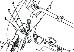
Install 2 harness fir clips into the 2 holes on back of the front light bracket (Figure 2).
Install the front light bracket to the machine using the existing holes with 2 hex-head screws (1/2 x 1–1/4 inches) and 2 locknut (1/2 inch); refer to Figure 2.
Install the 2 front light mounts to the front light bracket using 2 carriage bolts (1/4 x 2–1/4 inches) and 2 flange nuts (1/4 inch) on each (Figure 2).
On machines with 72-inch decks (Models 72029, 72074, and 72076), install the 2 extension brackets, to the front light bracket with 2 carriage bolts (1/4 x 2–1/4 inches), 2 flange nuts (1/4 inch), and 2 spacers on each; refer to Figure 2.
Install the left light assembly, marked LH, to the left side of front light bracket with the screw, washer and nut supplied with the light; refer to Figure 2.
Install the right light assembly, marked RH, to the right side of front light bracket with the screw, washer and nut supplied with the light; refer to Figure 2.
Note: Ensure both headlights are pointing straight forward.
Parts needed for this procedure:
| Control assembly | 1 |
| License plate and light assembly | 1 |
| Carriage bolt (1/4 x 5/8 inch) | 7 |
| Locknut (1/4 inch) | 7 |
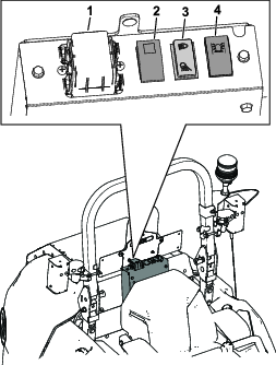
Remove the control-panel cover from the control assembly and retain the fasteners.
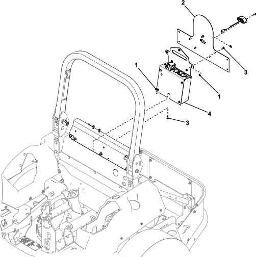
Install the control assembly to the frame of the machine with 2 carriage bolts (1/4 x 5/8 inch) and 2 locknuts (1/4 inch); refer to Figure 3.
Install the license plate mount to the control lights assembly with 5 carriage bolts (1/4 x 5/8 inch) and 5 locknuts (1/4 inch); refer to Figure 3.
Parts needed for this procedure:
| Left control-lever assembly | 1 |
Remove the existing left control lever and retain the fasteners.
Install the new left control lever with the light control switch.
Align the control levers and tighten them.
Parts needed for this procedure:
| Horn assembly | 1 |
| Hex-head bolt (M8 x 25) | 1 |
| Flange nut (M8) | 1 |
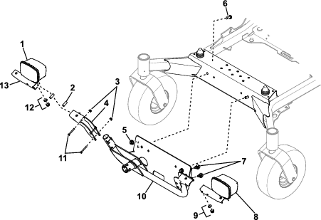
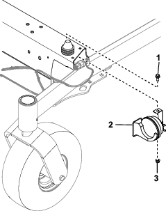
Drill a 8.5 mm hole in the beam between the front castor arms; refer to Figure 4 for the appropriate drilling location.
Install the horn assembly on the machine with a hex-head bolt (M8 x 25) and a flange nut (M8).
Parts needed for this procedure:
| Beacon light assembly | 1 |
| Beacon clamp | 1 |
| Beacon bracket | 1 |
| Beacon socket and wire harness assembly | 1 |
| Hex-head bolt (M8 x 30) | 2 |
| Washer (5/16 inch) | 2 |
| Flange nut (M8) | 2 |
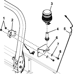
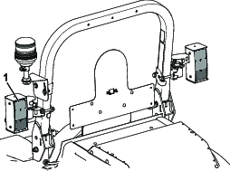
Loosely secure the beacon bracket to the left side of the roll bar, using the beacon clamp.
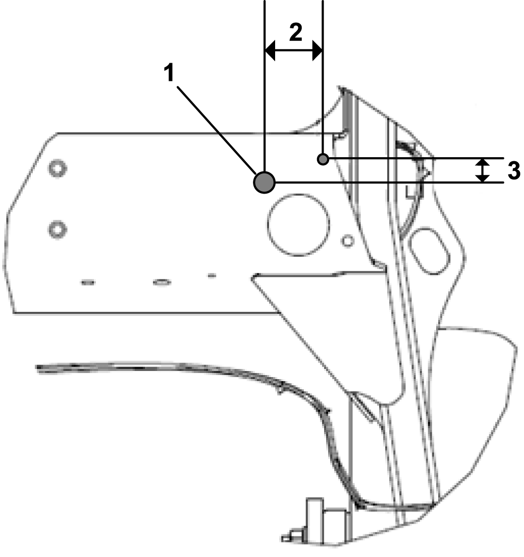
Note: The top surface of the bracket should be approximately 158 cm (62 inches) above the ground.
Secure the beacon socket to the beacon bracket using the nut, washer and serrated washer supplied with it.
Note: Ensure the socket is vertical when viewed from the side of the machine, adjust accordingly then tighten the bracket.
Route the wire harness from the beacon down the front of the roll bar frame and leave it loose for installation later.
Install the beacon light assembly to the beacon socket.
Parts needed for this procedure:
| Light kit wire harness | 1 |
| Magnetic harness anchor | 4 |
| Harness edge clip with tie | 2 |
| Button head screw (M6 x 16 mm) | 2 |
| Short cable tie | 10 |
| Long cable tie | 15 |
| Rear light | 2 |
| Screw (#10 x 1-1/4 inches) | 4 |
| Harness fir clip | 2 |
Support the seat and remove the left seat grill from the seat frame (Figure 11). Install the seat grill nuts to retain the seat frame.
Remove the foot plate.
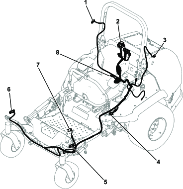
Lay the light kit wire harness through the left side of the frame under the seat and route the harness so that it comes out near the left rear deck lift stop. Then route the harness under the left chassis rail to the front horn position and then along the rear of the front light bracket. Refer to Figure 16.
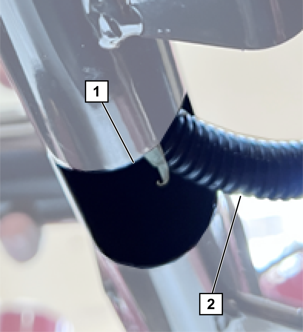
Locate the 2 front light connectors and remove both parts of the 90° backshell from each connector (Figure 7).
Note: Retain the backshells.
Identify and mark the left and right front light connectors. The right connector has blue, yellow, grey, and black wires. The left connector has brown, yellow, grey, and black wires.
Route the two front light connectors through the hole in the center of the front light bracket, and to each front light.
Install the previously removed 90° backshells onto the 2 front light connectors. Ensure that the harness conduit is secure to the shell.
Connect the front light connectors on the light kit harness to the front lights.
Secure the harness to the back of the light frame using the previously installed harness fir clips (Figure 2).
Connect the horn connectors on the light kit harness to the horn assembly.
Install 2 magnetic harness anchors to the underside of the left chassis rail below the operator platform (Figure 9).
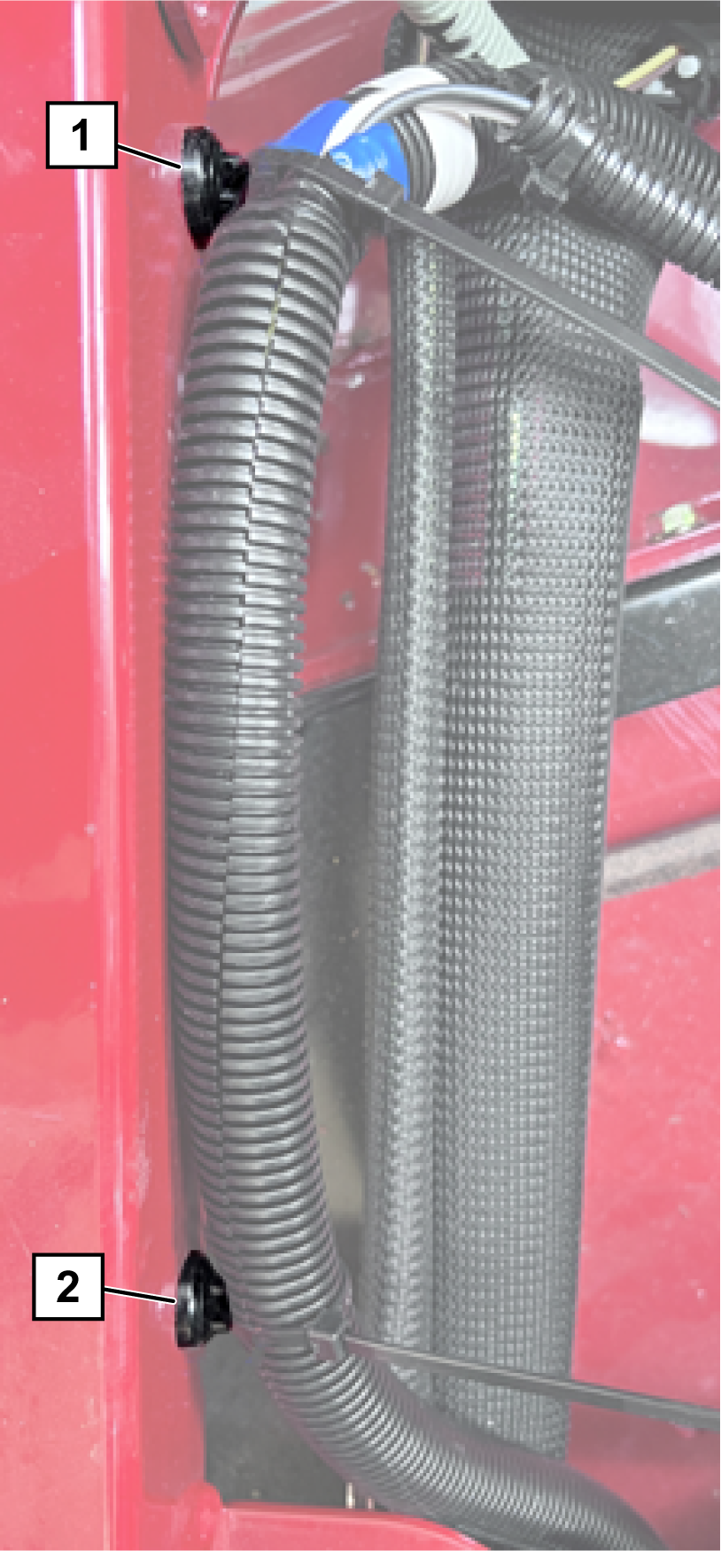
Secure the harness close to the left, rear deck stop using 1 magnetic harness anchor and cable ties.
Connect the multi-function switch connector on the light kit harness to the left control lever connector.
Install a harness edge clip with tie to the left side of the machine, as shown in Figure 10 and Figure 11.
Connect the beacon connector on the light kit harness to the beacon harness.
Route the left-rear light connector up the front of the roll bar frame next to the beacon wire harness. Push the connector through the rear light mount (Figure 12) and connect to the left rear light with 2 screws (#10 x 1-1/4 inches).
Note: Ensure that the direction-indicator light (red lens) is oriented on the top (Figure 13).
Adjust the light until it is 131 cm (51-1/2 inches) from the ground.
Repeat steps 16 and 17 for the right-rear light.
Use cable ties to secure the wires for the rear lights and beacon harness to the roll bar.
Note: Allow for some slack in the beacon harness to allow the roll bar to be folded.
Remove the fuse box cover and install the fuse box to the control panel with 2 button head screws (M6 x 16 mm).
Install the cover on the fuse box.
Connect the light kit wire harness to each switch, to the flasher unit, and to the license plate light.
Install the previously removed control-panel cover on the control assembly with the corresponding hardware.
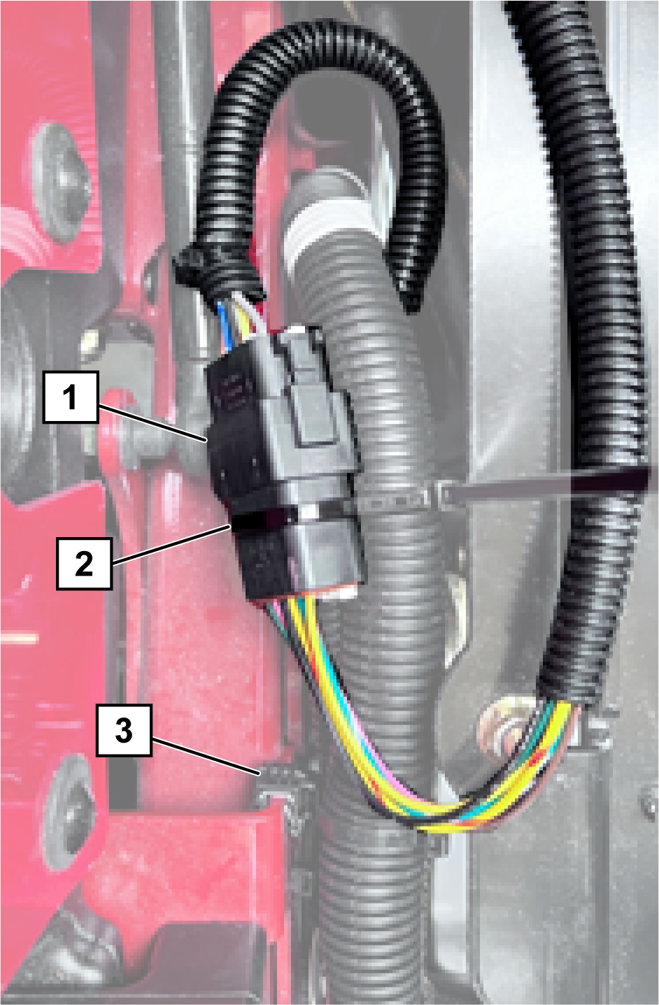
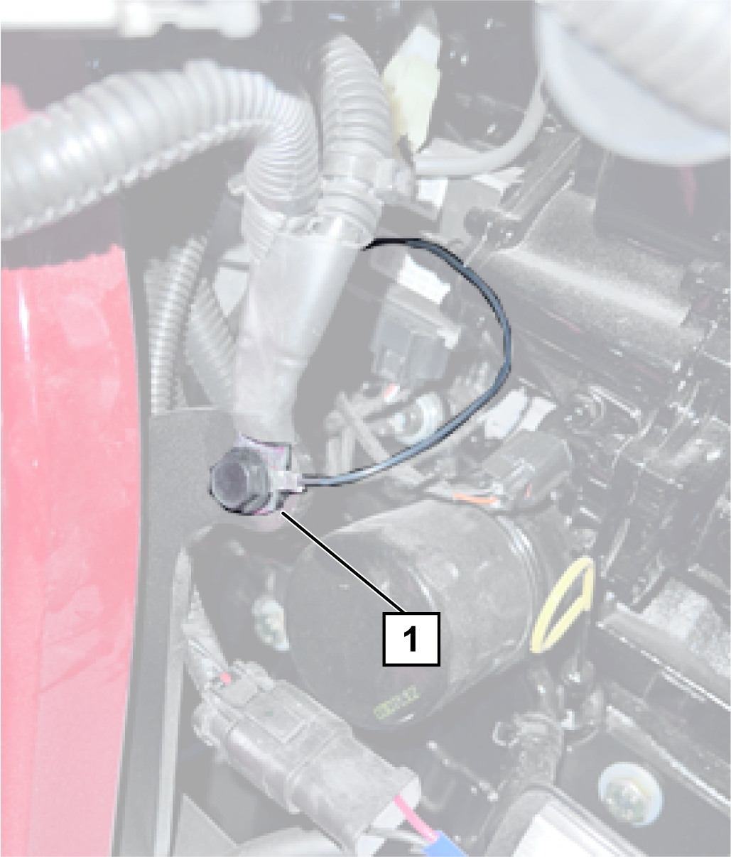
Connect the single black wire from the light kit wire harness to the ground on the left side of the machine behind the rear wheel (Figure 14).
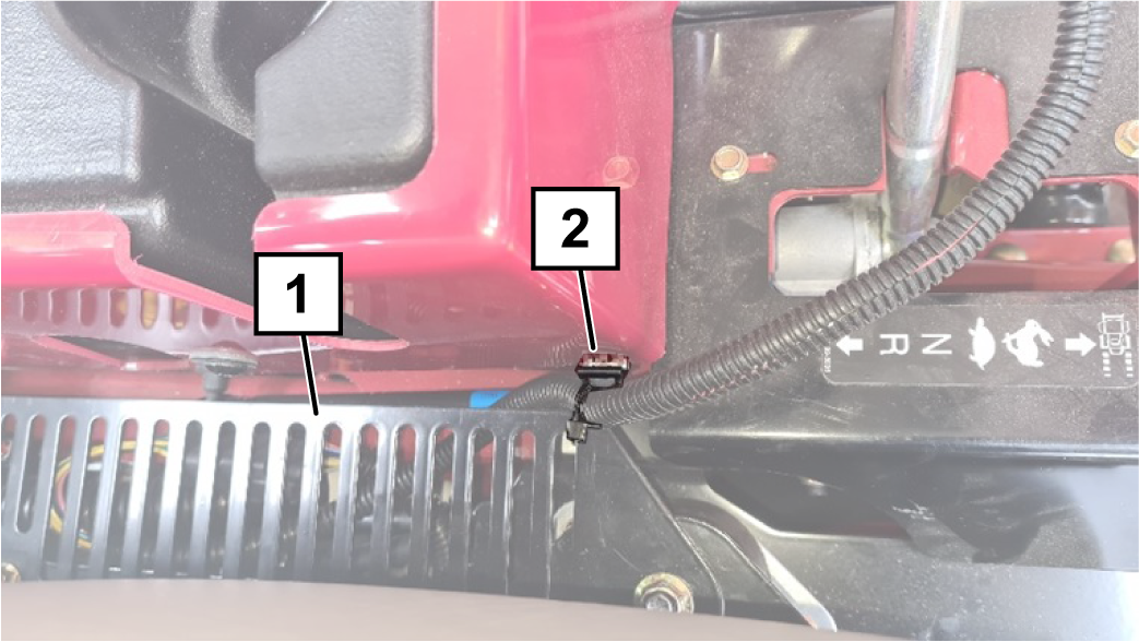
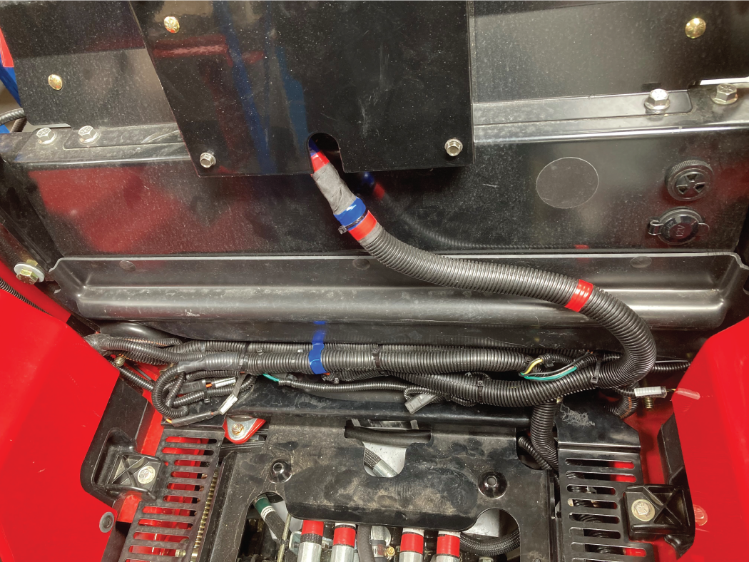
Connect the 3 pin accessory power-in connector on the light kit harness to the 3 pin accessory connector on the machine wire harness, located near the central bulkhead by the right ROPS post.
Drill two 6.5mm holes into the plastic bulkhead behind the seat and install 2 fir tree clips into the drilled holes.
Important: Use caution when drilling that the area behind the panel is open.
Using the fir tree clips behind the seat and a magnetic harness anchor, gather and secure the light kit wire harness behind the seat with the existing wires (Figure 15).
Connect the positive battery cable.
Connect the negative battery cable.
Secure all the wires and harnesses away from moving parts and hot parts with the remaining cable ties.
Install the previously removed left seat grill with the corresponding hardware.
With the ignition in the OFF position, switch on the hazard warning lights and ensure all 4 lights flash.
Switch the ignition switch to the RUN position, switch the beacon switch to the ON position, and check the beacon.
Switch the light switch, on the light control panel, rearward to activate the road lights. The side lights at the front and the red rear lights should come on.
Move to the left control arm and switch on the headlights. Ensure both lights have turned on.
To switch off the marker lights, move the light switch on the control panel, to the center position.
To operate the working lights (if present), switch the light switch on the control panel forward.
Note: The working lights cannot be used in conjunction with the road lights.
Check each direction indicator lights work. Ensure the correct lamp flashes when selected at the control arm switch.
Check the horn.
If all is working, use cable ties to secure the wire harnesses in all areas. You may need to loop some wires. Proceed to Installing the Reflectors, Speed Decals, and Light Kit Serial Number Decal.
If anything is not working, check the connections to the light that is failing and it’s switch.
Note: Ensure all grounded wires and battery connections are good.
Parts needed for this procedure:
| Red reflector | 2 |
| 20 Kph decal | 3 |
| 10 Kph decal (France only) | 3 |
| Vehicle information plate (Germany only) | 1 |
| Rivet (Germany only) | 4 |
| Light kit serial number decal | 1 |
Install a red reflector to each side of the rear of the machine (Figure 17).
Adhere the appropriate speed decal for your country to the license plate mount and both sides of the machine (Figure 18 and Figure 19).
For machines used in Germany, stamp the required information onto the machine vehicle information plate. See the table below for all models.
| TYP | Model Number |
| Fz-Ident-HR | Enter machines serial number |
| Zul- Gesamtgewicht Kg | 1416 |
| Baujahr | Enter year of manufacture |
| Zul-Achslast vorn Kg | 330 |
| Zul-Achslast Hinten Kg | 1086 |
For machines used in Germany, install the VIN plate as follows:
Hold the VIN plate up to the right side of the front caster arm and mark the 4 holes. Refer to Figure 20 for the appropriate orientation.
Drill a 3 mm hole in the 4 marked locations on the caster arm.
Note: Only drill through the outside face of the caster arm.
Rivet the VIN plate onto the right side of the front caster arm (Figure 20).
Adhere the light kit serial number decal next to the machine information plate (Figure 20).
If there is a requirement in your country to stamp the serial number on the machine frame, and the authority does not state a specified location, stamp the serial number on right caster arm.
Parts needed for this procedure:
| Speed control plate | 2 |
| Hex-head bolt (1/4 x 5/8 inch) | 2 |
| Locknut (1/4 inch) | 2 |
Important: This procedure is only for machines used in France.
Remove the bolt on the right motion-control cover and temporarily install the speed control plate with the existing bolt (Figure 21).
Using the speed control plate as a template, mark the location of the hole for the other fastener.
Remove the plate, drill a 7 mm diameter hole in the marked location, and remove all burrs from the hole.
Install the speed control plate on the right motion-control cover with the existing bolt and 1 hex-head bolt (1/4 x 5/8 inch) and 1 locknut (1/4 inch).
Repeat this procedure on the left motion-control lever.
Method 1—Using the Tachometer
Jack up the machine, and securely support it with jack stands so the wheels are off the ground.
Have someone sit in the operator’s seat or add a weight to the seat to activate the operator presence control switch in the seat.
Start the machine, release the brake, and push one control lever fully forward.
Use a tachometer to measure the wheel speed. The maximum speed should be 80 rpm.
If needed, adjust the speed control plates to set the required wheel speed.
Repeat the process for the wheel on the other side.
Method 2—Using the Ground Speed
Mark 2 lines on a straight, flat piece of ground 20 m (22 yd) apart.
Note: Allow enough room for the machine to accelerate to full speed before reaching the first line, and to brake at the other end, after passing the second line.
Measure the time it takes to drive at full speed (control arms fully forward) between the 2 marks. For 10 km/h, the time required should be 7 seconds max.
Adjust the control arm stop as per the tachometer method, and check the speed.
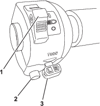
To illuminate the marker lights, run the engine and press the rear of the light switch on the control panel (Figure 22).
To switch off the marker lights, move the light switch on the control panel, to the center position.
To illuminate the headlights and marker lights, run the engine, press the rear of the light switch on the control panel and push the light switch on the left control arm to the I position (Figure 22).
To switch off the lights, move the light switch on the control panel to the center position.
To operate the working lights (if present), switch the light switch on the control panel forward.
Note: The working lights cannot be used in conjunction with the road lights.
To illuminate the hazard lights, press the top of the hazard light switch to flash all indicator lights simultaneously (Figure 22).
Note: You do not need the ignition switch in the RUN position.
The direction indicator switch operates the right-hand and left-hand direction indicator lights.
It works only if the ignition is switched to ON.
Press the left-hand side of the switch toggle to turn on the left-hand direction indicator lights.
Press the right-hand side of the switch toggle to the central (OFF) position to turn off the left-hand direction indicator lights.
Press the right-hand side of the switch toggle to turn on the right-hand direction indicator lights.
Press the left-hand side of the switch toggle to the central (OFF) position to turn off the right-hand direction indicator lights.
The horn switch operates the horn only when the ignition is switched on.
Push the button to sound the horn.
Release the button to stop the horn.
Periodically check that all lights are working.
Ensure that the headlights are adjusted correctly.
Clean the lights daily.
Keep the lenses clean by wiping them with a damp cloth. Do not use solvent-based cleaners.