Note: This kit is to be installed along with Model 41712 or Model 41713
Introduction
The GeoLink spray system kit is an attachment for a Toro Multi Pro turf spray application vehicle and is intended to be used by professional, hired operators in commercial applications. It is designed primarily for spraying on well-maintained lawns in parks, golf courses, sports fields, and on commercial grounds. Using this product for purposes other than its intended use could prove dangerous to you and bystanders.
Read this information carefully to learn how to operate and maintain your product properly and to avoid injury and product damage. You are responsible for operating the product properly and safely.
Visit www.Toro.com for product safety and operation training materials, accessory information, help finding a dealer, or to register your product.
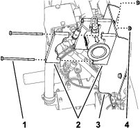
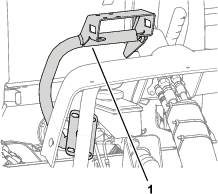
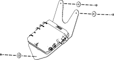
Whenever you need service, genuine Toro parts, or additional information, contact an Authorized Service Dealer or Toro Customer Service and have the model and serial numbers of your product ready. Figure 1 identifies the location of the model and serial numbers on the product. Write the numbers in the space provided.
Important: With your mobile device, you can scan the QR code (if equipped) on the serial number plate to access warranty, parts, and other product information.

This manual identifies potential hazards and has safety messages identified by the safety-alert symbol (Figure 2), which signals a hazard that may cause serious injury or death if you do not follow the recommended precautions.

This manual uses 2 words to highlight information. Important calls attention to special mechanical information and Note emphasizes general information worthy of special attention.
Safety
Warning
Chemical substances used in the spray system may be hazardous and toxic to you, bystanders, animals, plants, soil, or other property.
-
Carefully read and follow the chemical warning labels and safety data sheet (SDS) for all chemicals used and protect yourself according to the chemical manufacturer's recommendations. For example, use appropriate personal protective equipment (PPE), including face and eye protection, gloves, or other equipment to guard against personal contact with a chemical.
-
There may be more than 1 chemical used and information on each chemical; assess each chemical.
-
Refuse to operate or work on the sprayer if this information is not available.
-
Before working on a spray system, ensure that the system has been triple rinsed and neutralized according to the recommendations of the chemical manufacturer(s) and that all the valves are cycled 3 times.
-
Verify that there is an adequate supply of clean water and soap nearby, and immediately wash off any chemicals that contact you.
Safety and Instructional Decals
|
Safety decals and instructions are easily visible to the operator and are located near any area of potential danger. Replace any decal that is damaged or missing. |


Installation
Preparing the Machine
Refer to the Operator’s Manual for your machine.
-
Park the machine on a level surface and engage the parking brake.
-
Extend the left and right boom sections to the horizontal position.
-
Shut off the engine, remove the key, and disconnect the battery.
-
Clean the sprayer.
Important: You must completely empty the spray tank before installing the GeoLink Spray System Finishing Kit.
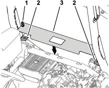
Removing the Seat and the Engine-Access Panel
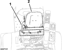
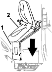
Removing the Seat
-
Remove the 2-socket connector of the machine wire harness that connects to the seat-switch connector.
-
Remove the hairpin that secures the prop rod to the bracket at the bottom of the seat plate.
-
Remove the 2 hairpins that secure the pivot fitting of the seat plate to the chassis brackets.
-
Remove the 2 pivot pins that secure the seat and seat plate to the chassis.
-
Lift the seat and seat plate up and out of the machine.
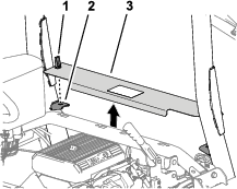
Removing the Engine-Access Panel
-
Rotate up the handles for the latches of the engine-access panel.
-
Lift the engine-access panel and remove it from the machine.
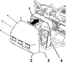
Removing the Front Fenders and the Hood
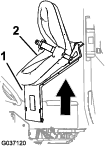
Removing the Left Front Fender
-
Remove and discard the 2 push-in fasteners that secure the left, front fender to the lower ROPS channel.

-
Remove the 3 bolts (5/16 x 1 inch) and 3 washers (5/16 inch) that secure the fender to the frame of the machine.

-
Remove the fender from the machine.
-
Remove the 6 push-in fasteners and 5 washers (9/16 x 1/2 inch) that secure the inner-fender shroud to the frame of the machine.

-
Remove the inner-fender shroud from the machine.

-
Repeat steps 1 through 5 for the fender and inner-fender shroud at the other side of the machine.
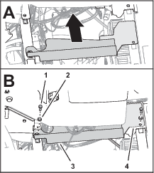
Removing the Right Front Fender
Note: If you damage the push-in fasteners removing them, replace the fasteners with Toro Part No. 117-2382.
-
Remove the 2 capscrews (5/16 x 1 inch) and 2 washers (5/16 inch) that secure the bottom console cover and end console cover to the machine, and remove the covers.


-
Remove the capscrew (5/16 x 1 inch) and washer (5/16 inch) that secures the right, front fender to the platform floor.
-
Carefully remove the 2 push-in fasteners that secure the right, front fender to the roll bar mounting channel.

-
Remove the capscrew (5/16 x 1 inch) and washer (5/16 inch) that secures the right, front fender to the cross-member support.

-
Remove the right, front fender from the machine.
-
Remove the 6 push-in fasteners and 5 washers (9/16 x 1/2 inch) that secure the inner-fender shroud to the right, upper and right, lower-frame tubes.

-
Remove the inner-fender shroud from the machine.
Note: Retain the right, front fender, inner-fender shroud, capscrews, washers, and undamaged push-in fasteners.Replace damaged push-in fasteners with Toro Part No. 117-2382.
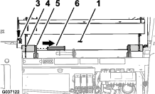
Removing the Hood
-
Disconnect the 2 electrical connectors (2-socket) of the machine wire harness from the 2-pin connectors of the left and right headlights.

-
Remove and retain the 9 push-in fasteners that secure the hood to the dash and frame of the machine.

-
Remove and discard the hood from the machine.
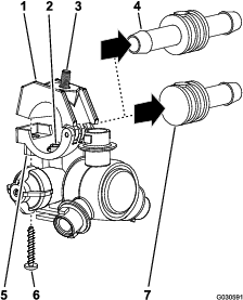
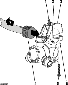
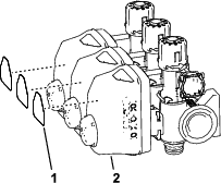
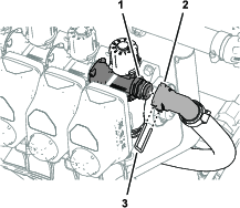
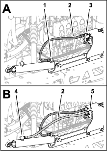
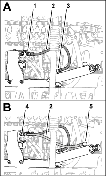
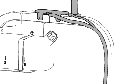
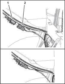
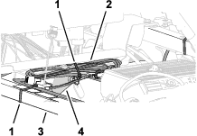
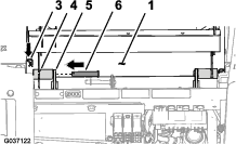
Disconnecting the Pressure-Sense Tube for the Dash Gauge
-
Press in the collar for the tube coupler in the end cap of the right boom-section valve.

-
Pull the pressure-sense tube for the dash gauge out of the tube coupler.
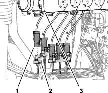
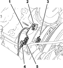
Disconnecting the Boom Valve Connectors
-
Disconnect the 3-socket connector labeled LEFT SPRAY VALVE, CENTER SPRAY VALVE, and RIGHT SPRAY VALVE of the machine wire harness from the 3-pin connectors of the 3 spray-valve actuators.

-
Disconnect the 4-socket connector of the machine wire harness labeled RATE VALVE from the 4-pin connector of the rate-valve actuator.
-
Disconnect the 3-socket connector of the machine wire harness labeled MASTER SPRAY VALVE from the 3-pin connector of the master spray-valve actuator.
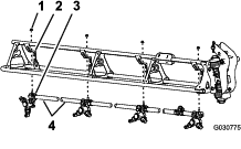
Removing the Boom Sections
Removing the Boom Section Hoses
-
At the outer boom section, remove the hose clamp that secures the hose to the barbed T-fitting.

-
Remove the hose from the T-fitting.
-
Remove the free end of the hose from the R-clamp.
-
Repeat steps 1 through 3 for the supply hose at the other outer-spray section.
-
Under the center-boom section, remove the hose clamp that secures the supply hose for the center-spray section to the barbed T-fitting.

-
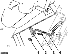
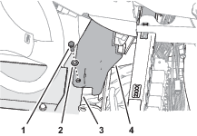
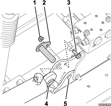
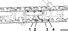
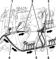
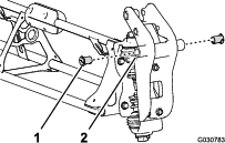
Remove and retain the retainers that secure the quick couplers of the left, center, and right supply hoses from the quick couplers if the section valves (Figure 24).

-
Remove and discard the left, center, and right section-supply hoses from the quick couplers of the section valves, and remove the hoses from the machine.
Removing the Extend and Retract Hoses for the Lift Cylinder
-
Remove the hoses from the extend ports of the left and right lift cylinders.

-
Remove and discard the hoses from the:
-
Ports C1, C2, C3, and C4 of the lift-cylinder manifold
-
Retract and extend ports of the left and right lift cylinder.
-
Removing the Lift Cylinders
Note: Except where noted, retain all hardware that you remove.
-
Use lifting equipment of the specified capacity to support the outer-spray section.
-
Remove the hairpin and clevis pin that secure the rod end of the lift cylinder to the pivot bracket.
-
Remove the flange locknut (5/16 inch) and flange-head bolt (5/16 x 3/4 inch) that secures the pivot pin to the cylinder mount.
-
Remove the pivot pin and the lift cylinder from the machine.
Removing the Outer-Boom Sections
Lift equipment capacity: 46 kg (100 lb)
Warning
Lifting heavy machines and attachments improperly could result in serious injury or even death.
When lifting heavy machines and attachments, use lifting equipment, such as chains and straps, that is rated for the weight of the equipment.
Note: Except where noted, retain all hardware that you remove; you will use the hardware to install the center-boom extension.
-
Remove the flange bolt (5/16 x 1 inch) and flange locknut (5/16 inch) securing the pivot pin to the pivot bracket.
-
Remove the pivot pin from the pivot bracket for the center-boom section and the pivot fitting for the outer-boom section.
-
Separate the outer-boom section from the center-spray section and remove outer section from the machine.
-
Remove and discard the 2 nylon-flange bushings from the pivot fitting of the outer-spray section.
-
Repeat steps 1 through 3 in Removing the Lift Cylinders for the outer-boom section at the other side of the machine.
-
Repeat steps 1 through 4 of this section for the outer-boom section at the other side of the machine.
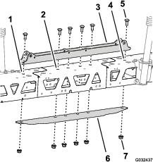
Removing the Section-Lift Manifold from the Center-Boom Section
-
Remove the 2 flange locknuts (5/16 inch) and 2 flange-head bolts (5/16 x 1 inch) that secure the support bracket for the section-lift manifold to the cylinder mount, and separate the manifold and bracket from the cylinder mount.

-
Support the section-lift manifold by tying it to the valve mount bracket with a piece of rope.
Removing the Center-Boom Section
Lifting-equipment capacity: 41 kg (90 lb)
-
Support the center-boom section with lifting equipment with the specified capacity.

-
Remove and retain the 4 flange-head bolts (3/8 x 1-1/4 inches) and 4 flange locknuts (3/8 inch) that secure the center boom section to the support brackets.

-
Lift the center boom section and remove it from the machine.
Installing the Center-Boom Extension
Parts needed for this procedure:
| Flange-head bolt (3/8 x 1 inch) | 2 |
| Flange locknuts (3/8 inch) | 2 |
| Center-boom extension | 1 |
| Cylinder mount (wide) | 1 |
| Tie plate (wide) | 1 |
| Carriage bolt (1/2 x 1-1/4 inches) | 4 |
| Flange locknut (1/2 inch) | 4 |
Removing the Turrets and Hoses
-
At the center-boom section, remove and retain the flanged locknut that secures the turret to the mount.
-
Remove the stainless steel screw (#12 x 1-1/4 inches) that secures the upper clamp half and double or single barbed-hose shank (3/4 inch) to the turret body, and separate the barbed-hose shank and hose from the nozzle.
Note: The hex-head bolt (5/16 x 3/4 inch—stainless steel) will separate from the upper clamp half when you open the clamp, retain the bolt for installation.
-
Remove the turret from the center-boom section.
-
Repeat steps 1 and 2 for the other 2 turrets.
-
Remove the hoses (3/4 inch inside diameter), barbed-hose shanks, clamps and barbed T-fitting from the center-boom section.
Note: You no longer need the hose, hose shanks, clamps, and T-fitting; retain all other parts.
Separating the Center-Boom Section Trusses
-
Remove the 2 flange head bolts (3/8 x 1 inch) and 2 locknuts (3/8 inch) that secure the vertical flanges of the left and right truss frames.
-
Remove the 2 carriage bolts (1/2 x 1-1/4 inches) and 2 locknuts (1/2 inch) that secure the narrow cylinder mount, left and right truss frames, and narrow tie plate.
Note: Retain the flange-head bolts, carriage bolts, and locknuts. You no longer need the narrow cylinder mount and narrow tie plate.
-
Separate the left and right truss frames.
Installing the Center-Boom Extension
-
Loosely assemble the center-boom extension to the truss frame with the previously removed 2 flange-head bolts (3/8 x 1 inch) and 2 flange locknuts (3/8 inch).
-
Loosely assemble the center-boom extension to the other truss frame with the 2 flange-head bolts (3/8 x 1 inch) and 2 flange locknuts (3/8 inch).
-
Insert the tie plate into the truss frame and center-boom extension and align the hole in the tie plate with the holes at the centerline of the trusses and boom extension.
-
Assemble the cylinder mount, trusses, center-boom extension, and tie plate using 6 carriage bolts (1/2 x 1-1/4 inches) and 6 flange locknuts (1/2 inch).
Note: 2 of the carriage bolts and locknuts are from previously removed parts.
-
Torque the 3/8 inch flange head bolts and flange locknuts to 37 to 45 N∙m (27 to 33 ft-lb).
-
Torque the 1/2 inch flange locknuts to 91 to 113 N∙m (67 to 83 ft-lb).
Installing the Turrets to the Center-Boom Section
Parts needed for this procedure:
| Turret | 2 |
| Hose assembly (valve 5 or 6) | 2 |
| Flange locknut (5/16 inch) | 2 |
Assembling the Turrets and Hoses for the Center-Boom Section
-
Using lifting equipment, raise the new center-boom section to a comfortable working height.
-
Remove the stainless steel screw that secures the upper clamp half to the saddle.
-
Locate the hole in the side of single barbed-hose shank at the end of the hose 25 cm (10 inches) of the hose assembly (valve 5 or 6) for the center-boom section.

-
Align the transfer tube in the saddle of a turret with the hole in the side of the single barbed-hose shank (1/2 inch).
-
Close the upper clamp half around the barbed-hose shank and secure the clamp half and spray-nozzle body with the stainless steel screw (#12 x 1-1/4 inches); torque the stainless steel screw to 14 to 18 N∙m (20 to 25 in-lb).
Important: Do not over tighten the stainless steel screw.
Note: Ensure that the hex-head bolt (5/16 x 3/4 inch) is seated in the recess in the upper clamp half when closing the clamp.
-
Repeat steps 3 through 5 to the single barbed-hose shanks of the other hose assemblies (spray valve 5 or 6) for the center-boom section.
Installing the Turrets and Hoses to the Center-Boom Section
-
Route the hose 13 mm (10 inches) and turret assembly between the truss braces of the outer truss.

-
Route the hose and turret above the truss brace and outward to the outboard nozzle mount.
-
Loosely secure the turret to the mount with the hex-head bolt (5/16 x 3/4 inch) and a flange locknut (5/16 inch).
-
Route the other hose 13 mm (10 inches) and turret assembly between the truss braces of the outer truss.
-
Route the hose and turret above the truss brace and inward to the inboard turret mount.
-
Loosely secure the turret to the mount with a the hex-head bolt (5/16 x 3/4 inch) and flange locknut (5/16 inch).
-
Torque the flange locknut to 1978 to 2542 N∙cm (175 to 225 in-lb).
-
Route the hose and barbed coupler 13 x 810 mm (1/2 x 32 inches) to the side of the center-spray section with the left and right support brackets.
-
Repeat steps 1 through 8 for the other hose and turret at the other outer truss.
Removing the Boom-Section Valves
Parts needed for this procedure:
| Cap (quick coupler) | 3 |
| Retainer | 3 |
Removing the Section Bypass Hose
-
Remove the small retainer that secures the quick-disconnect fitting of the bypass hose to the quick-disconnect fitting of the right section-bypass valve.

-
Remove and retain the large retainer that secures the 90° barbed fitting at the lower end of the bypass hose to the bulkhead fitting of the spray tank.

-
Remove and discard the bypass hose from the machine.
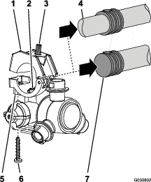
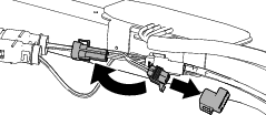
Positioning the Bypass Valves
-
Remove the 3 retainers that secure the 3 valve actuators to the left, center, and right section valves.

-
Remove the valve actuators from the left, center, and right section valves.
-
Remove the retainer that secures the cap to the quick disconnect fitting of the bypass valve, and remove and discard the cap.

-
Remove the 3 retainers that secure the 3 bypass valves to the left, center, and right section valves.
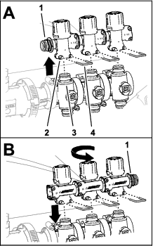
-
Lift the bypass valves from the section valves.
-
Rotate the bypass valves 180° and assemble them onto the quick disconnect fittings of the section valves.
-
Secure the 3 bypass valves to the section valves with the 3 retainers that you previously removed.
-
Assemble plug into the quick connect socket of the bypass valve.

-
Secure the plug to the quick connect socket with the previously removed retainer.
-
Assemble the 3 valve actuators onto the left, center, and right section valves with the previously removed retainers.
Removing the Section Valves from the Manifold Mount
-
Remove and discard the 2 flange-head bolts (1/4 x 3/4 inch) and 2 locknuts (1/4 inch) that secure the left boom-section valve to the manifold mount.

-
Remove the 2 flange-head bolts (1/4 x 3/4 inch) and 2 locknuts (1/4 inch) that secure the right boom-section valve to the manifold mount.
-
Remove the flange clamp 40 to 64 mm (1-9/16 to 2-1/2 inches) and gasket 25 x 35 mm (1 x 1-3/8 inches) that secures the flange of the left section valve to the adapter.
Note: Retain the 2 flange-head bolts, 2 locknuts, flange clamp and gasket.

-
Remove the 3 section valves from the machine.
-
Remove the decals from the actuators of the 3 section valves.
-
Remove and retain the flange clamp 51 mm (2 inches) and gasket 38 mm (1-1/2 inches) that secure the flange of the adapter to the flange of the flow meter.

Installing the Flow Meter Support Clamps
Parts needed for this procedure:
| Flow meter mount | 1 |
| Support-clamp half | 4 |
| Bolt (1/4 x 4-1/2 inches) | 4 |
| Flange locknuts (1/4 inch) | 4 |
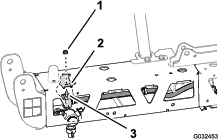
Removing the Section-Valve Bracket
-
Disconnect the 3-socket connector of the machine wire harness labeled FLOW METER from the 3-pin connector of the flow meter.
-
Remove the 2 push-in fasteners of the machine wire harness from the bottom flange of the section-valve bracket.
-
Remove the 4 flange-head screws (5/16 x 3/4 inch) that secure the section-valve bracket from the valve mount, and remove the valve bracket from the machine.
Note: Retain the 4 flange-head screws; you no longer need the section-valve bracket.
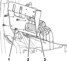
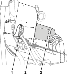
Installing the Flow Meter Mount and Clamps
-
Align the holes in the flow-meter bracket with the holes in the valve mount.
-
Assemble the flow-meter bracket to the valve mount with the previously removed 4 flange-head screws, and torque the screws to 1978 to 2542 N∙cm (175 to 225 in-lb).
-
Assemble the pair of clamp halves to the flow meter bracket with 2 bolts (1/4 x 4-1/2 inches) and 2 flange locknuts (1/4 inch).
-
Torque the bolts and nuts to 1017 to 1243 N∙cm (90 to 110 in-lb).
Assembling the Rear Harness to the Machine
Parts needed for this procedure:
| Rear harness | 1 |
Routing the Rear Harness


-
Route the 84 cm (33 inch), 60 cm (23-1/2 inch), and 66 cm (26 inch) wire-harness branches of the rear harness to the left side of the machine along the machine wire harness.

-
Route the 84 cm (33 inch), 60 cm (23-1/2 inch), and 66 cm (26 inch) wire-harness branches of the rear harness forward along the left frame channel.


-
Route the 84 cm (33 inch), 60 cm (23-1/2 inch), and 66 cm (26 inch) wire-harness branches of the rear harness along the machine wire harness, outboard of the parking-brake assembly.
-
Route the 84 cm (33 inch), 60 cm (23-1/2 inch), and 66 cm (26 inch) wire-harness branches of the rear harness across the shock-support tube.

-
Secure the rear harness to the machine wire harness.
-
At the back of the machine, route the 89 cm (35 inch) wire-harness branch forward of the lift manifold, and to the right of the flow meter.
-
Route the 102 cm (40 inch) wire-harness branch rearward of the lift manifold and to the right.
Connecting the Left, Center, and Right Spray-Valve Connectors
-
Connect the 3-pin connector of the 89 cm (35 inch) rear harness branch labeled LEFT SPRAY to the 3-socket connector of the machine wire harness labeled LEFT SPRAY VALVE.
-
Connect the 3-pin connector rear harness labeled CENTER SPRAY to the 3-socket connector of the machine wire harness labeled CENTER SPRAY VALVE.
-
Connect the 3-pin connector of the rear harness labeled RIGHT SPRAY to the 3-socket connector of the machine wire harness labeled RIGHT SPRAY VALVE.
-
Insert the push-in fastener of the rear harness into the hole in the flange of the flow-meter bracket.
Connecting the Flow Meter, Master Section Valve, and Rate Valves Electrical Connectors
-
Connect the 3-socket electrical connector of the 89 cm (35 inch) rear harness branch labeled FLOW METER into the 3-pin connector of the flow meter.

-
Connect the 3-pin connector of the 89 cm (35 inch) rear harness branch labeled MASTER VALVE into the 3-socket connector of the machine wire harness labeled MASTER SPRAY VALVE.

-
Connect 3-pin connector of the actuator for the master-spray valve into the 3-socket connector of the 89 cm (35 inch) rear harness branch labeled MASTER VALVE.
-
Connect the 4-pin connector of the actuator for the rate valve into the 4-socket connector of the 89 cm (35 inch) rear harness branch labeled RATE VALVE.
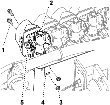
Assembling the Flow-Meter Manifold
Parts needed for this procedure:
| Straight hose barb (1 x 2 inches) | 1 |
| Hose clamp (3/4 to 1-1/2 inches) | 3 |
| Hose (1 x 5-3/4 inches) | 1 |
| Manifold | 1 |
| Hose (1 x 16 inches) | 1 |
Assembling the Manifold
-
Assemble hose (1 x 5-3/4 inches) on to the straight hose barb (1 x 2 inches) with a hose clamp (3/4 to 1-1/2 inches), and tighten the clamp by hand.
-
Assemble the other end of the hose (1 x 5-3/4 inches) onto the barbed fitting of the manifold with a hose clamp and tighten the hose clamp by hand.
-
Assemble the hose (1 x 16 inches) onto the other barbed fitting of the manifold with a hose clamp, and tighten the clamp by hand.
Assembling the Manifold to the Flow Meter
-
Assemble the straight hose barb (1 x 2 inches) to the flange of the flow meter with the gasket 38 mm (1-1/2 inches) and flange clamp 51 mm (2 inches).
-
Tighten the flange clamp by hand.
Installing the Bypass Hoses to the Tank
Parts needed for this procedure:
| Bypass hose assembly | 1 |
| Shutoff valve | 1 |
Assembling the Bypass Hoses to the Tank
-
Align the bypass hose assembly to the tank.
-
Secure the 90° barbed fitting to the bulkhead fitting of the tank with a retainer.
Installing the Modified Center-Boom Section
Lifting-equipment capacity: 55 kg (120 lb)
-
Using lifting equipment with the specified lift capacity, raise the center-boom section and align the boom section with the holes in the support brackets.

-
Assemble the center-boom section to the support brackets with the 4 flange-head bolts (3/8 x 1-1/4 inches) and 4 flange locknuts (3/8 inch).
-
Torque the nuts and bolts to 37 to 45 N∙m (27 to 33 ft-lb).
Assembling the Lift Cylinder Manifold to the Cylinder Mount
-
Untie the lift manifold from the valve-mount bracket.
-
Align the holes in the support bracket for the section-lift manifold with the holes in the cylinder mount.

-
Assemble the support bracket to the cylinder mount with the 2 flange-head bolt (5/16 x 1 inch) and flange locknut (5/16 inch).
-
Torque the bolts and nuts to 1978 to 2542 N∙cm (175 to 225 in-lb).
Installing the Valve Mount, Rate/Section Controller, and Section Valves
Parts needed for this procedure:
| Valve mount and valve assembly | 1 |
| Rate/Section controller | 1 |
| Magnet | 4 |
| Bolt (#8) | 4 |
| Flat washer | 4 |
| Locknut (#8) | 4 |
| Cap (quick-disconnect fitting) | 2 |
| Flange-head bolts (5/16 x 3/4 inch) | 8 |
| Flange locknuts (5/16 inch) | 8 |
| Hose clamp | 1 |
| Push-in fastener (cable tie) | 1 |
| Push-in fastener (connector anchor) | 3 |
Installing the Controller to the Valve Mount
-
Secure the magnets to the controller using 4 bolts (#8), 4 washers, and 4 locknuts (#8).

-
Place the controller assembly onto the valve mount.

Assembling the 3 Section Valves to the Valve Mount
-
Assemble the 3 section valves onto the flange of valve 7 of the spray valve assembly with the flange clamp and gasket.
Important: The left, center, and right section valves are identified in the GeoLink sprayer system as follows: left section valve—nozzle 8, center section valve—nozzle 9, and right section valve—nozzle 10.

-
Secure the socket of the quick-disconnect coupling for bypass valve of section valve 8 to the quick-disconnect coupling for bypass valve of section valve 7 with the previously removed retainer.

-
Assemble nozzle valve 10 to the valve mount the with the previously removed 2 flange-head bolt (1/4 x 3/4 inch) and 2 locknuts (1/4 inch).

-
Torque the flange-head bolts and locknuts to 1017 to 1243 N∙m (90 to 120 in-lb).
Assembling the Valve Mount and Section Valve Assembly to the Machine
Lifting-equipment capacity: 23 kg (50 lb)
-
Using lifting equipment with the specified capacity, lift the valve mount and section valve assembly and align it over the center-boom section.

-
Align the holes on the mount bracket of the valve mount to the holes on the truss frame of the center boom section.

-
Assemble the valve mount to the truss frame with 4 bolts (5/16 x 3/4 inch) and 4 flange locknuts (5/16 inch).

-
Repeat steps 2 through 3 for the other mount bracket of the valve mount at the other truss frame.
-
Torque the flange-head bolts and flange locknuts to 1978 to 2542 N∙cm (175 to 225 in-lb).
Assembling the Hose to the Valve Manifold
-
Assemble the hose (1 x 16 inches) over the 90° flange fitting (1 inch).

-
Secure the hose to the flange fitting with a hose clamp.
-
Assemble the cable tie/push-in fastener into the hole at the top of the valve mount.
-
Secure the cable tie/push-in fastener around the hose (1 x 16 inches).
Installing the Section Bypass Hoses
-
Remove the retainers from the sockets of the quick-connect fittings.
-
Assemble the quick-connect fitting of the bypass hose to the quick disconnect fitting at the bypass valve at section valve 10.
-
Secure the quick disconnect fittings for the bypass hose and the bypass valve with the retainer.
-
Repeat steps 1 through 3 for the quick disconnect fittings at section valve 1.
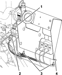
Connecting the Rear Harness at the Back of the Machine
Connecting the Section Valve Electrical Connectors
-
Assemble the push-in fasteners of the valve actuator electrical-connectors into the holes in the valve mount.

-
Connect 3-socket connector of the 89 cm (35 inch) rear harness branch labeled NOZZLE VALVE 1) into the 3-pin connector of the left most valve actuator (position 1).
Note: The valve actuator positions 1 through 10 are arranged from left to right when standing behind the machine.
-
Connect 3-socket connector of the 89 cm (35 inch) rear harness branch NOZZLE VALVE 2) into the 3-pin connector of the valve actuator (position 2).
-
Connect the remaining 3-socket connectors of the 89 cm (35 inch) rear harness branch into the 3-pin connector of the valve actuators.
Note: Ensure that the 3-socket connector are connected to the related valve actuator position.
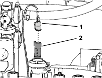
Connecting the Rear Harness to the Pressure Transducer
Insert the 3-socket connector 61 cm (24 inch) branch of the rear harness labeled PRESSURE TRANSDUCER GREEN WEDGE into the 3-pin connector of the pressure transducer.
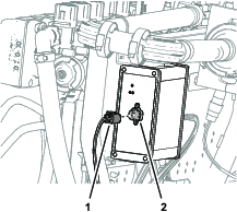
Connecting the Rear Harness to the ASC 10
-
Insert the 40-socket connector of the 102 cm (40 inch) branch of the rear harness into the 40-pin connector if the ASC 10 spray controller.

-
Thread the thumb screw of the 40-socket connector into the ASC 10 connector by hand.
-
Insert the 4-socket connector of the rear harness labeled TO ASC 10 into the 4-pin connector of the ASC 10 spray controller.
Assembling the Boom-Lift Cylinders
Parts needed for this procedure:
| Hydraulic hose (1/4 x 24-3/4 inches) | 4 |
Assembling the Lift Cylinders
-
Align the fixed end of the lift cylinder to the 16 mm (5/8 inch) hole in the cylinder mount.
Note: Ensure that the extend and retract ports of the cylinder align up.

-
Assemble the cylinder to the cylinder mount with the pivot pin, flanged-head bolt, and flange nut.
-
Torque the bolt and nut to 1978 to 2542 N·cm (175 to 225 in-lb).
-
Repeat steps 1 through 3 for the other lift cylinder at the other side of the cylinder mount.
Installing the Lift-Cylinder Hoses
-
Loosely assemble a new hydraulic hose (1/4 x 24-3/4 inches) between the extend port of the left boom-lift cylinder and port C3 of the boom-lift manifold.
-
Loosely assemble a new hydraulic hose (1/4 x 24-3/4 inches) between the retract port of the left boom-lift cylinder and port C4 of the boom-lift manifold.
-
Loosely assemble a new hydraulic hose (1/4 x 24-3/4 inches) between the extend port of the right boom-lift cylinder and port C1 of the boom-lift manifold.
-
Loosely assemble a new hydraulic hose (1/4 x 24-3/4 inches) between the retract port of the right boom-lift cylinder and port C2 of the boom-lift manifold.
-
Torque the hose fittings at the extend and retract ports of the lift cylinders to 21 to 26 N∙m (15 to 19 ft-lb).
-
Torque the swivel nuts of the hoses at the boom-lift manifold to 24 to 30 N∙m (17 to 22 ft-lb).
Installing the Outer-Boom Sections
Parts needed for this procedure:
| Nylon-flange bushing | 4 |
| Supply-hose assembly 188 cm (74 inches) | 1 |
| Supply-hose assembly 234 cm (92 inches) | 1 |
| Supply-hose assembly 279 cm (110 inches) | 1 |
Removing the Turrets from the Outer-Boom Sections
-
Cut the hose between 2 turrets.
-
Remove the flange locknut (5/16 inch) that secures the turret to the turret mount.
-
Repeat the steps for the other 3 turrets.
Note: Retain the flange locknut and turrets.
Note: Discard the hoses, clamps, and T-fitting.
-
Repeat the steps for the other outer-boom section.
-
Remove the stainless steel screws (#12 x 1-1/4 inches) that secures the upper clamp halves and the double or single barbed-hose shanks (3/4 inch) to the body of each of the sprayer nozzle, and remove the barbed-hose shanks.
Note: The hex-head bolt (5/16 x 3/4 inch—stainless steel) will separate from the upper clamp half when you open the clamp, retain the bolt for installation.
Assembling the Outer-Boom Sections to the Machine
Lift equipment capacity: 46 kg (100 lb)
-
Using lift equipment with the specified capacity, raise the outer boom.
-
Insert a nylon-flange bushing into the 31.8 mm (1-1/4 inches) hole at each side of the pivot fitting.
-
Align the bushings in the pivot fitting with the holes in the flanges of the pivot bracket at the end of the center-boom section.
-
Assemble the pivot fitting to the pivot bracket with the pivot pin, flange bolt (5/16 x 1 inch), and flange locknut (5/16 inch).
-
Torque the bolt and nut to 1978 to 2542 N∙cm (175 to 225 in-lb).
-
Align the rod end of the lift cylinder with the hole 25 mm (1 inch) in the horn of the pivot fitting.
-
Secure the lift cylinder to the pivot fitting with the clevis pin and hairpin.
-
Repeat steps 1 through 7 at the outer-boom section at the other side of the machine.
Installing the Hoses
Parts needed for this procedure:
| Supply hose 279 cm (110 inches) | 2 |
| Supply hose 234 cm (92 inches) | 2 |
| Supply hose 188 cm (74 inches) | 4 |
| Supply hose 81 cm (32 inches) | 2 |
Assembling the Hoses to Section Valves
Note: Ensure that the barbed fitting is fully seated onto the coupler.
Secure the barbed fittings to the couplers with a retainer.
Note: The supply hose assembly 81 cm (32 inches) has a T-fitting with 2 branch hoses and 2 single barbed-hose shanks.
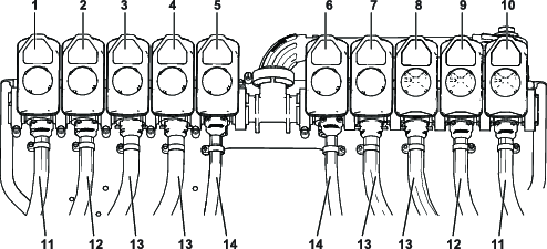
| Boom Section | Section valve | Nozzle | Supply Hose |
|---|---|---|---|
| Left | 1 | 1 | 279 cm (110 inches) |
| 2 | 2 | 234 cm (92 inches) | |
| 3 | 3 | 188 cm (74 inches) | |
| 4 | 4 | 188 cm (74 inches) | |
| Center | 5 | 5 and 6 | 81 cm (32 inches) |
| 6 | 7 and 8 | 81 cm (32 inches) | |
| Right | 7 | 9 | 188 cm (74 inches) |
| 8 | 10 | 188 cm (74 inches) | |
| 9 | 11 | 234 cm (92 inches) | |
| 10 | 12 | 279 cm (110 inches) |

Routing the Hoses


Installing the Turrets at the Outer-Boom Sections
-
Align the transfer tube in the saddle of a turret [with the hole in the side of the single barbed-hose shank (1/2 inch)].
-
Close the upper clamp half around the barbed-hose shank and secure the clamp half and turret body with the stainless steel screw (#12 x 1-1/4 inches); torque the stainless steel screw to 14 to 18 N∙m (20 to 25 in-lb).
Note: Ensure that the hex-head bolt (5/16 x 3/4 inch) is seated in the recess in the upper clamp half when closing the clamp.
-
Secure the turrets to the mounts using the previously removed flange locknuts (5/16 inch).
-
Torque the flange locknut to 1978 to 2542 N∙cm (175 to 225 in-lb).
Connecting the Pressure-Sense Tube for the Dash Gauge
Connecting the Pressure-Sense Tube for the Dash Gauge
-
Align the end of the pressure-sense tube (plastic) for the pressure gauge in the dash with the locking collar for the tube coupler.
-
Insert the sense tube into the locking collar until the tube is fully seated.
Installing the Navigation Receiver
Parts needed for this procedure:
| Navigation-receiver plate | 1 |
| Receiver mount | 1 |
| Bolt (3/8 x 3-1/4 inches) | 1 |
| Lock washer (3/8 inch) | 1 |
| Washer (3/8 x 13/16 inch) | 1 |
| Spacer (3/8 x 1 inch) | 1 |
| Flange locknut (3/8 inch) | 1 |
| Flange-head bolt (5/16 x 3/4 inch) | 1 |
| Flange locknut (5/16 inch) | 1 |
| Flange-head bolt (3/8 x 1-1/2 inches) | 2 |
| Spacer (3/8 x 7/16 inch) | 2 |
| Navigation receiver | 1 |
| Modem antenna bracket | 1 |
| Hex-head bolt (5 x 16 mm) | 3 |
| Washer (5 mm) | 3 |
Assembling the Navigation Receiver Mount
-
Secure the receiver plate to the receiver mount using 1 bolt (3/8 x 3-1/4 inches), 1 lock washer, 1 washer, 1 spacer (3/8 x 1 inch), and 1 locknut (3/8 inch).
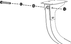
-
Assemble the flange-head bolt (5/16 x 3/4 inch) and flange locknut (5/16 inch) through the smaller hole in the receiver mount and the slot in the receiver plate.

-
Tighten the bolts and nuts so that you can rotate the receiver plate with slight resistance.
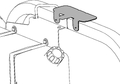
Installing the Navigation Receiver Mount to the Machine
-
Assemble the receiver mount and spacer (3/8 x 7/16 inch) to the roll bar with the flange-head bolt (3/8 x 1-1/2 inches).
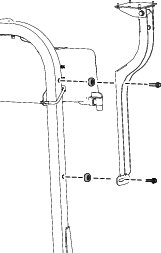
-
Tighten the bolts so that you can rotate the receiver plate with slight resistance.
-
Level the receiver plate left to right.
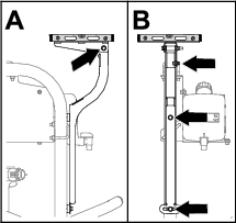
-
Torque the flange-head bolt (5/16 x 3/4 inch) and flange locknut (5/16 inch) to 1978 to 2542 N∙cm (175 to 225 in-lb).
-
Level the receiver plate front to back.
-
Torque the bolt (3/8 x 3-1/4 inches) and flange locknut (3/8 inch) to 37 to 45 N∙m (27 to 33 ft-lb).
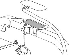
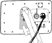
Assembling the Navigation Receiver to the Machine
-
Install the receiver onto the mount using 4 bolts (5 x 16 mm) and 4 washers.
Note: Ensure that both arrows are pointing toward the front of the machine.
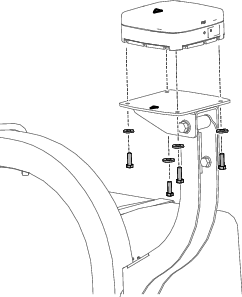
-
Torque the 3 bolts to 576 to 712 N∙cm (51 to 63 in-lb).
Installing the Modem Antennas to the Machine
Parts needed for this procedure:
| Antenna mount | 1 |
| Rivet | 2 |
| Magnet | 2 |
| Modem antenna | 1 |
| High gain antenna | 1 |
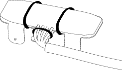
Installing the Modem Antennas
-
Install the modem antenna bracket to the roll bar.
-
Clean any grease or oil from the antenna mount surface.
-
Remove the backing from the double sided adhesive liner and adhere the antenna to the mount.
-
Secure the antenna and wire harness to the mount with 3 cable ties.
-
Place the high gain antenna next to the other antenna on the roll bar.

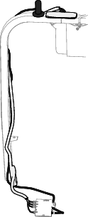
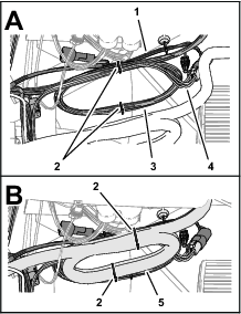
Routing the Modem-Antenna Harnesses
-
Route the modem-antenna harnesses to the right, along the roll bar.
-
Route the harness down and forward.

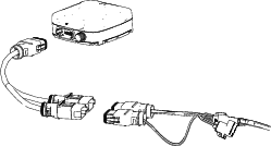
Installing the Wire Harnesses for the Navigation Components
Parts needed for this procedure:
| Harness adapter | 1 |
| Data and electrical harness | 1 |
| Cable tie | 8 |
Identifying the Navigation-Data and Electrical Harness

Connecting the Navigation-Data and Electrical Harness to the Navigation Receiver
-
Route the 302 cm (119 inches) branch of the navigation-data and electrical harness along the right ROPS tube with the 12-socket connector (gray) and 12-socket connector (black) up toward the navigation receiver.
-
Connect the 2 connectors at the long face of the 12-socket connector of the data harness labeled with the 2 connector slots into the adapter harness.
-
Plug the adapter harness into the receiver.
Routing the Navigation-Data and Electrical Harness to the Right Side of the Machine
-
Route the navigation-data and electrical harness along the right roll bar tube and the modem-antenna harness to the cross member for the seat support.
-
Secure the harnesses to the roll bar with cable ties.
Note: Ensure that the harness is slack between the 12-socket connectors and the cable tie.
-
Route the 227 cm (89-1/2 inches) branch of the navigation-data and electrical harness along the bottom of the control console of the machine.

-
Route the 258 cm (101-1/2 inch) branch of the navigation-data and electrical harness across the shock-support tube and toward the battery.
Connecting the CAN 2/ASC 10 Power Connector
-
Adhere the magnetic mount of the rear harness to the right, upper tube frame of the machine.

-
Plug the 4-pin connector labeled of the data harness into the 4-socket connector labeled of the rear harness.
Installing the Display
Parts needed for this procedure:
| Display mount | 1 |
| Flange-head bolt (6 x 12 mm) | 3 |
| U-bolt (5/16 inch) | 2 |
| Flange-head bolt (5/16 x 3/4 inch) | 4 |
| Flange locknut (5/16 inch) | 8 |
| Ball mount | 1 |
| Display Arm | 1 |
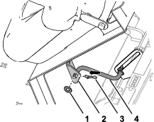
Removing the Steering Wheel
-
Mark the position of the steering wheel to the steering valve with a piece of tape.
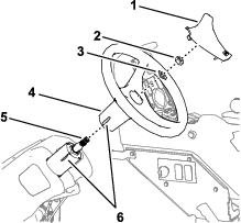
-
Remove the cover from the steering wheel.
-
Remove the nut (5/8 inch) and washer (5/8 inch) that secure the steering wheel to the steering valve, and remove the steering wheel.
Installing the Display Mount
-
Align the display mount to the machine as shown.
-
Assemble the display mount to the housing of the steering valve with the 3 flange-head bolts (6 x 12 mm).

-
Assemble the plate of the display mount to the support tube of the machine chassis with the 2 U-bolts and 4 flange locknuts (5/16 inch).

-
Torque the 3 flange-head bolts (6 x 12 mm) at the steering valve to 972 to 1198 N∙cm (86 to 106 in-lb); At the support tube, torque the flange locknuts to 1978 to 2542 N∙cm (175 to 225 in-lb).
Installing the Steering Wheel
-
Align the tape mark on the steering wheel to the tale mark on the housing of the steering valve.

-
Assemble the steering wheel onto the shaft of the steering valve with the previously removed washer (5/8 inch) and nut (5/8 inch).
-
Torque the nut to 206 to 254 N∙m (152 to 188 ft-lb).
-
Install the cover.
Installing the Display to the Mount
-
Assemble the ball mount to the bracket for the display mount with the 4 flange-head bolts (5/16 x 3/4 inch) and 4 flange locknuts (5/16 inch).

-
Torque the bolts and nuts to 1978 to 2542 N∙cm (175 to 225 in-lb).
-
Assemble the ball fitting of the display and the ball mount on the machine to the long display arm.

-
Adjust the display so that it is viewable from the machine operator’s position and tighten the display arm knob by hand.
Connecting the Data Cable to the Display
Routing and Connecting the Navigation-Data and Electrical Harness to the Display
-
Route the 227 cm (89-1/2 inch) branch of the navigation-data and electrical harness (the branch with the 26-socket connector) up and along the support tube for the display.
-
Plug the navigation data harness into the monitor.
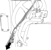
Removing the Terminating Resistor
Remove the terminating resistor from the 6-socket connector labeled CAN 2 TERMINATOR of the data cable as shown.
Note: You no longer need the terminating resistor.
Assembling the Modem Data Harness to the Machine
Parts needed for this procedure:
| Modem data harness—300 cm (118 inches) | 1 |
Connecting the Modem Data Harness to the Display
Screw the modem harness connector into the display.

Routing the Modem Data Harness
-
Route the modem data harness along the data harness for the display.
-
Route the modem data harness under the shock-support tube of the machine
-
Route the modem data harness across the back if the relays and down.

-
Align the 4-pin connector labeled of the modem data harness near the 4 connectors for the modem-antenna harness as shown.

Securing the Navigation-Data and Electrical Harness, Modem-Antenna Harness, and Modem Data Harness
-
At the right, upper tube frame, bundle the navigation-data and electrical harness, and the CAN 2 ASC 10 BUS wire harness branch to the kit sprayer harness with 2 cable ties.
-
Bundle the modem-antenna harness and secure it to the kit sprayer harness bundle with 2 cable ties.
-
Secure the modem-data harness and the navigation-data and electrical harness to the monitor tube with a cable tie.

-
Secure the modem-data harness to the navigation-data and electrical harness with a cable tie.
Assembling the Modem Power Harness to the Machine
Parts needed for this procedure:
| Modem power harness | 1 |
-
Align the modem power harness to the machine.

-
Route the ring terminals of the modem power harness labeled and toward the battery.

-
Route the 4-pin connector labeled and the 18-socket connector labeled of the modem power harness under the fuse block of the machine.
-
At the front of the machine, route the 4-pin connector labeled and the 18-socket connector labeled of the modem power harness to the machine as shown.

-
Plug the terminal of the modem power harness labeled into the socket connector for options power of the fuse block (.
Note: If fuse block of your machine does not have an available options-power circuit, install an additional options-fuse block; refer to your authorized Toro distributor.
-
Near the fuse block bundle the modem power-harness at the 9-pin connector labeled and secure the harness with 2 cable ties as shown.

-
Bundle the modem power-harness at the negative battery cable, and secure the bundle to the battery cable with a cable tie.
-
Insert the fuse (10 A) into the fuse-block socket (Figure 145) for the options power circuit that you used in step 5.

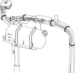
Installing the CL-55 Modem
Parts needed for this procedure:
| CL-55 modem | 1 |
| Modem bracket | 1 |
| Bolt (#10-24 x 1-3/8 inches) | 2 |
| Locknut (#10-24 inch) | 2 |
| Magnet | 2 |
| Rivet | 2 |
Installing the Modem to the Machine
-
Remove the push-in fastener that secures the wire harness of the machine to the prop-rod bracket.

-
Secure the modem to the bracket using 2 bolts (#10-24 x 1-3/8 inches) and 2 nuts (#10-24).

-
Secure the magnets to the modem bracket using the rivets.
-
Place the modem bracket under the prop-rod bracket and behind the flange of the machine frame.

-
Insert the upper push-in fastener of the wire harness into the holes in the prop-rod bracket.

Connecting the Antenna Harness to the Modem
-
Plug the coaxial connector of the modem-antenna harness labeled into the coaxial port of the CL-55 modem marked WIFI/BT, and tighten the coaxial connector.
-
Plug the blue coaxial push-in connector of the modem-antenna harness labeled into the connector of the CL-55 modem marked , until the connectors latch securely.
-
Plug the violet coaxial push-in connector of the modem-antenna harness labeled into the connector of the CL-55 modem marked , until the connectors latch securely.
-
Plug the red coaxial push-in connector of the modem-antenna harness labeled into the connector of the CL-55 modem marked , until the connectors latch securely.
Connecting the Modem Data and Power Harnesses to the Modem
-
Plug the 4-pin connector of the modem data harness labeled into the 4-socket connector (unmarked) of the CL-55 modem, and tighten the knurled nut of the 4-pin connector.
-
Plug the 18-socket connector of the modem power harness labeled into the 18-pin connector of the CL-55 modem.
Removing the Passive Resistor from the Machine Wire Harness
At the inboard side of the control console of the machine, remove and retain the passive terminating resistor from the unlabeled 3-pin connector of the machine wire harness.

Installing the ISO-CAN Bus Harness
Parts needed for this procedure:
| ISO-CAN bus harness—302 cm (119 inches) | 1 |
Connecting the ISO Bus Harness to the Navigation-Data and Electrical Harness
-
At the front of the control console of the machine, route the connector labeled of the ISO-CAN bus harness into the bottom of the display.

-
Remove the cap from the 4-socket connector labeled of the navigation-data and electrical harness.

-
Plug the 4-pin connector labeled of the ISO-CAN bus harness into the 4-socket connector labeled of the navigation-data and electrical harness.
-
Route the connectors labeled and of the ISO-CAN bus harness toward the fuse block.


Connecting the ISO Bus Harness to the Machine Wire Harness
-
At the fuse block, remove the cap from the 3-socket connector labeled of the machine wire harness.

-
Plug the 3-pin connector labeled of the ISO-CAN bus harness into the 3-socket connector labeled of the machine wire harness.
Important: Do not connect the harness connectors labeled and of the rear harness.
Securing the ISO Bus Harness
-
Bundle the ISO-CAN bus harness and secure it to the navigation-data and electrical harness with a cable tie.

-
Secure the ISO-CAN bus harness and navigation-data and electrical harness to the right frame tube with a cable tie as shown.
Installing the Adapter Harness and Terminating Resistor
Parts needed for this procedure:
| Adapter harness—13 cm (5 inches) | 1 |
-
At the satellite receiver, remove and discard the ISO bus terminator for the 6-socket connector of the GeoLink harness.
-
Plug the 6-pin connector of the adapter harness—13 cm (5 inches) into the 6-socket connector of the GeoLink harness.
-
Plug the resistor into the 3-socket connector of the adapter harness.
-
Secure the adapter harness to the GeoLink harness with a cable tie.
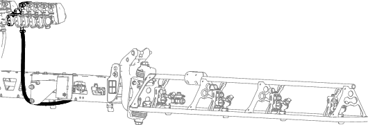
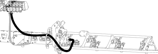
Wiring the Spray Pump Clutch
-
Disconnect the 2-socket connector of the machine wire harness labeled from the 2-pin connector of the pump clutch.

-
Connect the 2-pin connector of the kit sprayer harness branch—84 cm (33 inches) into the 2-socket connector of the machine wire-harness labeled .
-
Connect the 2-socket connector of the kit sprayer harness into the 2-pin connector of the pump clutch.
-
Route the wire-harness branch—84 cm (33 inches) against the engine and spray pump so that the harness clears the alternator belt.

Installing Components for the Electrical System
Parts needed for this procedure:
| Battery bracket | 1 |
| Bumper | 1 |
| Flange-locknut (1/4 inch) | 2 |
| Strap | 1 |
| Battery (650 A) | 1 |
| Alternator bracket | 1 |
| Drive pulley 279 mm (11 inch) | 1 |
| Bolt (1/4 x 2-1/4 inches) | 4 |
| Alternator (60 A) | 1 |
| Flange-head bolt (8 x 25 mm) | 1 |
| Flange-head bolt (3/8 x 1-1/2 inches) | 1 |
| V-belt | 1 |
Removing the Battery (300 A) and Battery Bracket
-
Remove the 2 flange locknuts and hold-down rod from the 2 J-bolts that secure the battery to the battery bracket of the machine.

-
Remove and discard the 2 J-bolts and battery tray from the battery bracket.

-
Remove the battery from the machine.
Note: You no longer need the flange nuts, hold-down rod, and battery (300 A).
-
Remove and retain the 3 bolts (10-24 x 3/4 inch) and 3 nuts (10-24) that secure the fuse blocks to the battery bracket.

-
Remove and retain the 2 flange-head bolts (3/8 x 3/4 inch) that secure battery bracket to the shock-support tube of the machine.
-
Remove and retain the 2 bolts (10-24 x 3/4 inch), 2 locknuts (10-24), and wire-support clip that secure the ground block and wire to the battery bracket.
Note: Discard the wire support clip.

-
Remove and discard the battery bracket from the machine.

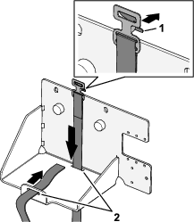
Assembling the Battery Bracket
-
Assemble the 2 bumpers to the battery bracket with 2 flange locknuts (1/4 inch).

-
Assemble the strap through the 2 slots in the battery bracket.
Installing the Battery Bracket and Battery (650 A)
-
Align the new battery bracket to the shock-support tube of the machine and the fuse blocks.

-
Assemble the battery bracket to the shock-support tube with the previously removed 2 flange-head bolt (3/8 x 3/4 inch).

-
Torque the flange head bolts to 37 to 45 N∙m (27 to 33 ft-lb).
-
Secure the ground block and to the battery bracket with the previously removed 2 bolts (10-24 x 3/4 inch), 2 locknuts (10-24) and secure the wire-support clip to the edge of the bracket.
-
Secure the fuse blocks to the battery bracket with the 3 previously removed bolts (10–24 x 3/4 inch) and 3 nuts (10-24).

-
Assemble the battery (650 A) into the battery bracket.

-
Feed the webbing of the battery strap through the buckle, and tighten the strap until the battery is secure.
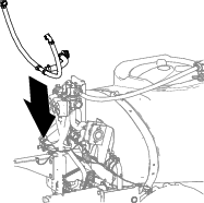
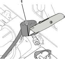
Installing the Alternator Bracket
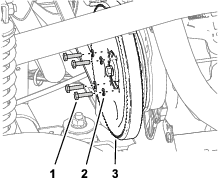
-
At the pump head, loosen the 2 bolts to provide a 7 to 10 mm (1/4 to 3/8 inch) gap between the head of the bolts and the pump.
Note: You do not need to remove the bolts from the spray pump.

-
Align the alternator bracket between the bolts and the pump head.

-
Torque the bolts to 61 to 75 N (45 to 55 ft-lb).
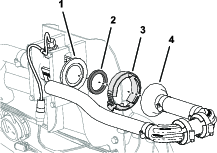
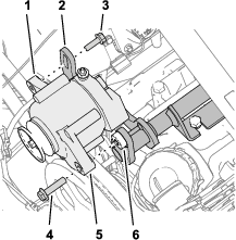
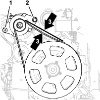
Installing the Drive Pulley
-
Loosen the nut for the idler-pulley shaft.
Note: Ensure that there is no belt tension.

-
Rotate the belt-tension bolt to remove all tension from the sprayer-pump belt.
-
Remove the 4 bolts (1/4 x 1 inch) and 4 lock washers (1/4 inch) that secure the pulley to the sprayer pump.
Important: Do not remove the pulley.
Note: Retain the lock washer; you no longer need the bolts.
-
Align the holes in the pulley for the alternator (kit) with the holes in the pulley for the sprayer pump.

-
Assemble the alternator pulley to the sprayer-pump pulley and sprayer pump with the 4 bolt (1/4 x 2-1/4 inches) and 4 lock washers (1/4 inch).
-
Torque the bolts to 1017 to 1243 N∙m (90 to 110 in-lb).
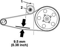
-
Rotate the belt-tension bolt to increase the tension of the belt until you measure belt 9.5 mm (3/8 inch) of belt deflection when you apply 4.5 kg (10 lb) halfway between the engine and spray pump sprockets.
-
Tighten the nut for the idler-pulley shaft to 37 to 44 N∙m (27 to 33 ft-lb).
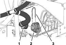
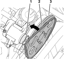
Installing the Alternator
-
Assemble the alternator (60 A) to the threaded boss of the alternator-bracket ith the flange-head bolt (3/8 x 1-1/2 inches).
-
Assemble the threaded flange of the alternator to the slotted flange of the alternator bracket with the flange-head bolt (8 x 25 mm).
-
Assemble the V-belt over the drive pulley 279 mm (11 inch) and the pulley of the alternator.
-
Rotate the alternator up to increase tension on the belt until you measure belt 9.5 mm (3/8 inch) of belt deflection when you apply 4.5 kg (10 lb) halfway between the alternator pulley and drive pulley 279 mm (11 inch).
-
Torque the flange-head bolt (8 x 25 mm) to 23 to 29 N∙m (17 to 21 ft-lb).
-
Torque the flange-head bolt (3/8 x 1-1/2 inches) to 37 to 45 N∙m (27 to 33 ft-lb).
Connecting the Harness at the Seat Base
Parts needed for this procedure:
| Alternator cable (red—6 gauge) | 1 |
| Relay | 1 |
| Push-in fastener | 1 |
| Fuse (15 A) | 1 |
Connecting the Alternator (50 A)
-
Connect the 2-socket at the end of the pink wire 57 cm (23-1/2 inches) of the harness onto the 2-pin connector of the alternator (50 A).
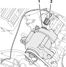
-
Route the pink sense wire away from the alternator belts and secure the wire with a cable tie.
-
Remove the nut from the terminal post of the alternator (50 A).

-
Assemble the end of the red, 6 gauge alternator cable with the insulator cover onto the terminal post of the alternator (50 A) with the nut.
-
Route the other end of the alternator cable toward the battery posts, away from the pulley and alternator belt.
-
Torque the nut to 47 to 57 N∙m (34 to 42 ft-lb).
-
Slip the insulator cover over the terminal post of the alternator.
Connecting the ASC 10 Enable Relay
-
Connect the 5-pin connector of the relay into the 5-socket connector of the harness labeled ASC 10 ENABLE RELAY.

-
Align the hole in the mounting tab of the relay with the hole in the shock-support tube, and secure the relay to the tube with a push-in fastener.
Connecting the Fuse Blocks
-
Prepare a multi-meter for preforming a continuity test.
-
At fuse block 3 of the machine, insert the multi-meter probe into contact 4 (the right column) of fuse-socket 2.
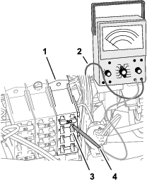
-
At the front side of the fuse blocks, use the other multi-meter probe to identify the blade connector at the end of the red 10-gauge wire that connects to fuse-socket 2—contact 4.

-
Use a piece of tape to mark the connector and wire that you identified in the previous step.
-
Connect the blade connector that you marked in the previous step into the socket connector at the end of the pink wire 51 mm (2 inches) of the harness.

-
Insert the fuse (15 A) into fuse-socket 2 of fuse block 3 until the fuse is fully seated.

Installing the Navigation-Data and Electrical Harness
Parts needed for this procedure:
| Quick-connect clamp (red handle) | 1 |
| Quick-connect clamp (black handle) | 1 |
Assembling the Quick-Disconnect Clamps to the Battery
-
Remove the hex nuts and washers from the handle quick-connect clamps.
-
Open the latch handle of the quick-connect clamp with the black handle.

-
Assemble the quick-connect clamp onto the negative battery post, with the threaded post of the clamp aligned toward the center of the battery.
-
Close the latch handle of the quick-connect clamp.
Note: If you need to adjust the clamping force of the quick-connect clamp, open the handle, rotate the knurled nut to increase or decrease the clamping force, and close the handle for the clamp.
-
Repeat the steps for the red handle clamp on the positive battery post.
Connecting the Battery
Warning
Incorrect battery cable routing could damage the machine and cables causing sparks. Sparks can cause the battery gasses to explode, resulting in personal injury.
-
Always disconnect the negative (black) battery cable before disconnecting the positive (red) cable.
-
Always connect the positive (red) battery cable before connecting the negative (black) cable.
Warning
Battery terminals or metal tools could short against metal components causing sparks. Sparks can cause the battery gasses to explode, resulting in personal injury.
-
When removing or installing the battery, do not allow the battery terminals to touch any metal parts of the machine.
-
Do not allow metal tools to short between the battery terminals and metal parts of the machine.
-
Slit the insulator cover of the positive battery cable to the starter.
-
Assemble the following wire and cable terminals onto the threaded post of the positive battery terminal in the following order:
Important: Ensure that the battery-cable terminal (positive) to the engine starter is positioned at the top of the stack of terminals on the threaded post.
-
Ring terminal—165 cm (65 inch) modem power harness branch (labeled
-
Battery-cable terminal (positive)—to the alternator (50 A)
-
Ring terminal—258 cm (101-1/2 inch) navigation-data and electrical harness branch (labeled )
-
Ring terminal—21.6 cm (8-1/2 inch) machine harness branch (labeled )
-
Ring terminal—24 cm (9-1/2 inch) kit sprayer-harness branch (unlabeled)
-
Battery-cable terminal (positive)—to the engine starter

-
-
Assemble the hex nut (1/4 inch) and washer (1/4 inch) onto the threaded post, and torque the nut to 1017 to 1234 N∙cm (90 to 110 in-lb).
-
Align the insulator cover of the positive battery cable to the starter over the threaded post.
-
Assemble the following wire and cable terminals onto the threaded post of the negative battery terminal in the following order:
Important: Ensure that the battery-cable terminal (negative) to the engine and chassis ground is positioned at the top of the stack of terminals on the threaded post.
-
Ring terminal—258 cm (101-1/2 inch) navigation-data and electrical harness branch (not labeled—black wire insulation)
-
Ring terminal—165 cm (65 inch) modem power harness branch (labeled )
-
Battery-cable terminal (negative)—to the engine and chassis ground

-
Securing the Harness
-
Gather the excess length of the data harness against the right, upper-frame tube.
-
Align the data harness to the shock-support tube, and secure the harness to the tube with a cable tie.
-
Align the data-harness bundle to the right, upper-frame tube, and secure the harness bundle to the frame tube with a cable tie.
-
Ensure that there is clearance between the pulleys and belts and the data harness, battery harness, kit wire harness, and battery cables.
Secure the wire harness and cables with cable ties as needed to provide clearance away from the belts and pulleys.
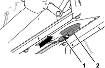
Removing the Rate-Control Switch
Parts needed for this procedure:
| Switch plug | 1 |
-
Remove the 4 flange head screws (1/4 x 1/2 inch) that secure the 3-switch panel to the control console.

-
Squeeze the lock tabs of the rate-control switch together and push up the switch out of the 3-switch panel.

-
Disconnect the 8-socket connector of the machine wire harness (labeled Rate Switch) from the 8-pin connector of the switch.
Note: You no longer need the rate switch that you removed from the machine.
-
Route the branch of the front harness for the rate switch through the opening in the 3-switch panel and secure the wiring branch against an adjacent wire branch with a cable tie.
-
Assemble the 3-switch panel to the control console ith the 4 flange head screws (1/4 x 1/2 inch) that you removed in step 1.
-
Align the switch plug to the opening in the 3-switch panel where you removed the rate switch.
-
Insert the switch plug into the 3-switch panel until the plug snaps into the panel securely.
Installing the Hood and the Front Fenders
Parts needed for this procedure:
| Push-in fastener | 13 |
Installing the Hood
-
Align the hood holes in the hood with the holes in the dash panel and frame of the machine.
-
Secure the hood to the dash and frame with 9 push-in fastener.
-
Connect the 2 electrical connectors (2-socket) of the machine wire harness from the 2-pin connectors of the left and right headlights.
Installing the Left Front Fender
-
Align the inner-fender shroud to the left, upper- and left, lower-frame tubes.

-
Secure the inner-fender shroud to the frame tubes with the 6 push-in fasteners.
-
Align the holes in the fender with the holes in the frame of the machine.
-
Loosely assemble the fender to the frame with the previously removed 3 bolts (5/16 x 1 inch) and 3 washers (5/16 inch).
-
Secure the fender to the frame channel with the 2 push-in fasteners.
-
Torque the bolt (5/16 x 1 inch) to 1978 to 2542 N∙cm (175 to 225 in-lb).
-
Repeat steps 1 through 6 for the inner-fender shroud and fender at the other side of the machine.
Installing the Right Front Fender
-
Align the inner-fender shroud to the right, upper and right, lower-frame tubes.
-
Secure the inner-fender shroud to the frame tubes with the 6 push-in fasteners and 5 washers (9/16 x 1/2 inch).
-
Align the right, front fender to the machine and align the holes in the fender with the holes in the frame.

-
Secure right, front fender to the clip nut of the cross-member support with the capscrew (5/16 x 1 inch) and washer (5/16 inch).
-
Secure the right, front fender to the roll bar mounting channel with 2 push-in fasteners.
-
Align the hole in the right, front fender with the hole in the platform floor and secure the fender to the floor with a capscrew (5/16 x 1 inch) and washer (5/16 inch).
-
Align the hole in the bottom console cover to the hole in the shock-support tube and the hole in the end console cover to the hole in the cross-member tube.
-
Secure the covers to the tubes with 2 capscrews (5/16 x 1 inch) and 2 washers (5/16 inch).
Installing the Engine-Access Panel and the Seat
Installing the Engine-Access Panel
-
Align the latches of the engine access panel with the bushings in the panel-support brackets on the roll bar.
-
Assemble the panel onto the brackets.
-
Rotate the handles latches down to secure the panel to the brackets.
Installing the Seat
-
Align the seat and seat plate to the chassis of the machine.
-
Align the holes in the pivot fittings of the seat pan with the holes in the chassis bracket.
-
Assemble the seat pan to the chassis brackets with the 2 pivot pins.
-
Secure the pivot pins to the machine with the 2 hairpins.
-
Assemble the prop rod to the bracket of the seat with the washer and hairpin.
-
Plug the 2-socket connector of the machine wire harness into the connector for the seat switch until the connectors latch securely.
-
Rotate the seat forward slightly, remove the prop rod from the detent, rotate the seat down until the seat latches securely.
Programming the Machine Settings
-
Insert the key into the key switch and rotate it to the ON position.
The splash screen appears in the InfoCenter display and the indicator light illuminates briefly.
Note: Do not start the engine.
-
At the Home screen, press the center button on the InfoCenter to access the navigation screen.
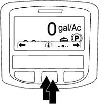
-
Press the center button on the InfoCenter to access the Main Menu.
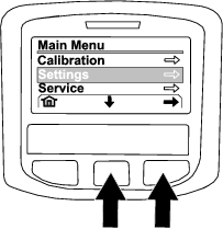
-
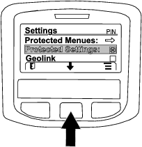
At the MAIN MENU screen, press the center button to navigate to the SETTING option, and press the right button to select the option.
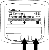
-
At the SETTING screen, press the center button to navigate to the PROTECTED SETTINGS option, and press the right button to select the option.
-
Enter the PIN code as follows:
-
Press the center button as needed to enter the PIN code number for the left position.
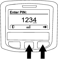
-
Press the right button to navigate to the next PIN code number position.
-
Repeat steps 1 and 2 for the 3 other PIN code number positions.
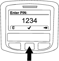
-
When all the PIN code numbers are entered press the right button and then press the center button to enter the PIN code.
The indicator light illuminates briefly.
-
-
Press the center button to navigate to the GEOLINK option, and press the right button to set the option.
The GeoLink confirmation screen displays in the InfoCenter.

-
Rotate the ignition switch to the OFF position and then to the ON position.
-
The GEOLINK splash screen initially appears when you rotate the key switch to the ON position.

Powering the GeoLink Components
-
Turn the ignition key to the RUN (gasoline) or PREHEAT/RUN (diesel) position.
-
Verify that the following components indicate that each receives power:
-
Control console—displays graphics and text

-
Satellite receiver—the PWR indicator illuminates

-
Modem—the LED indicators illuminate.

-
Automatic section controller—the STATUS indicator illuminates

-
-
Turn the ignition key to the OFF position.
-
Verify that power is shut off at the following components:
-
Control console
-
Satellite receiver
-
Automatic section controller
-
Completing the Software Setup
Refer to the Software Guide for your GeoLink system.
Complete the following procedures:
-
Verify the software version.
-
Select the units of measure.
-
Create a field.
-
Create a new product and application rate.
-
Create a spray task.
-
Balance the section valvesthis topic is not in the 5800.check SG
-
Checking the spray system.
-
Balance the agitation bypass valve.
-
Calibrate the flow meter.
-
Verify the cellular status.
-
Calibrate the compass at the distributor location.
-
Clear the NVRAM at the customer location.
-
Calibrate the compass at the customer location.