Installation
Preparing the Machine
-
Position the machine on a level surface, lower the cutting units, shut off the engine, engage the parking brake, and remove the key from the ignition.
-
Disconnect the negative battery cable from the battery.
-
Disconnect the seat switch wire from the harness at the rear of the control arm.
-
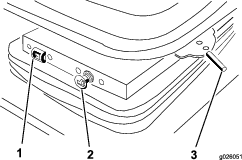
Remove the 2 adjusting bolts securing the control arm to the seat mount (Figure 1). Carefully set the control arm aside.
Important: Ensure that you do not damage the wire harness or the throttle cable.
-
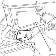
Remove the 4 nuts securing the seat adjusters and the manual tube clamps to the seat suspension (Figure 2).
-
Remove the 4 washers between the seat adjusters and seat suspension and remove the seat assembly; carefully set the seat assembly aside.
-
Remove the 4 bolts, spacers, and nuts securing the lower seat brackets to the seat base (Figure 2).
-
Remove the seat suspension and the seat brackets from the seat base.
Important: Ensure that you do not misplace the spacers during removal.
-
Remove the 4 bolts securing the seat suspension to the lower seat brackets (Figure 2).
Important: Retain the removed bolts and brackets for later installation.
Installing the Seat
-
Secure the air ride seat suspension to the lower seat brackets with the 4 bolts previously removed (Figure 2).
Note: When assembling the seat components, use the front mounting holes in the seat and the rear mounting holes in the suspension.
-
Mount the lower seat brackets to the seat base with the 4 bolts, spacers, and nuts previously removed (Figure 2).
-
Position the seat assembly onto the seat suspension. Ensure that a washer is on each adjuster stud before placing it on the suspension (Figure 2).
-
Secure the seat adjusters and the manual tube clamps to the seat suspension with the 4 nuts previously removed (Figure 2).
-
Install the control arm with the 2 control arm adjusting bolts previously removed (Figure 1). Adjust as desired.
-
Plug the seat switch connector into the wire harness at the rear of the control arm.
-
Locate the air ride seat suspension plug on the wire harness at the rear of the control arm. Remove the plug from the connector on the harness. Plug the seat suspension connector into the wire harness connector.
Installing the Fuse
Parts needed for this procedure:
| Fuse – 20A | 1 |
| Fuse block | 1 |
| Screw | 1 |
Note: Newer models are equipped with updated electronics and do not require installation of the included fuse, fuse block, or screw.
-
Remove the access panel from the side of the control arm (Figure 1).
View the decal on the back side of the access cover for the optional air ride seat suspension fuse location;
-
If there is an open slot in the fuse block for the suspension, insert a 20A fuse and proceed to Completing the Installation.
-
If there is no fuse slot available for the suspension, continue this procedure.
-
-
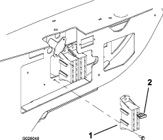
Mount the fuse block next to the existing fuse block with 2 screws (#8 x 1/2 inch) as shown in Figure 3.
-
Connect the large red wire from the traction unit wire harness to the wire on the fuse block.
-
Connect the red wire with the white stripe labeled “Air Ride Seat” to one of the red wires from the fuse block.
-
Insert the 20A fuse into the fuse slot where the wire is connected.
-
Install the access panel to the control arm (Figure 1).
-
Plug the traction unit power harness from back of control arm into the seat harness connector.
Completing the Installation
-
Slide the seat completely forward and backward to ensure proper operation and that the seat wires and connectors are not pinched or do no contact any moving parts.
-
Connect the negative battery cable to the battery.