Note: Determine the left and right sides of the machine from the normal operating position.
Note: The procedures for installing this kit require that you work from under the machine.
Safety
Safety and Instructional Decals
 |
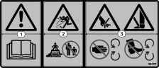
Safety decals and instructions are easily visible to the operator and are located near any area of potential danger. Replace any decal that is damaged or missing. |

Installation
Preparing the Machine
Caution
If you leave the key in the ignition switch, someone could accidently start the engine and seriously injure you or other bystanders.
Remove the key from the ignition switch before you perform any maintenance.
Important: Cap or plug any disconnected hydraulic hoses, tubes, or component ports to prevent system contamination.
-
Park the machine on a level surface or move the machine to a machine lift.
-
Engage the parking brake.
-
Shut off the engine and remove the key.
-
Wait for all moving parts to stop and allow the engine to cool.
-
Move the hydraulic controls forward and backward to relieve hydraulic pressure; refer to your Operator’s Manual.
-
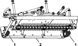
Remove the multi-tool attachment from the pallet, and position it beneath the machine with the grader toward the back of the machine.
Installing the Lift Links
Parts needed for this procedure:
| Multi-tool attachment assembly | 1 |
| Lift link | 2 |
| Locknut (1/2 inch) | 4 |
| Washer (1/2 inch) | 2 |
| Carriage bolt (1/2 x 2-1/2 inches) | 4 |
-
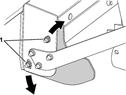
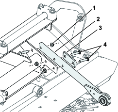
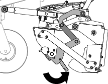
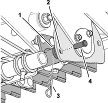
Install, but do not tighten, the lower portion of a lift link to the frame using a carriage bolt (1/2 x 2-1/2 inch), thrust washer, and locknut (Figure 1).
-
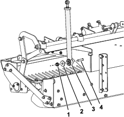
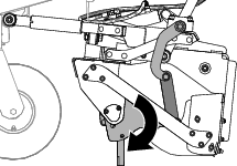
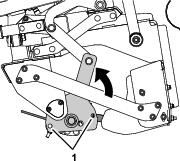
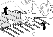
Rotate the lift link up and align it with the lift-arm bracket, and rotate the rod end until the hole in the rod end aligns with the hole in the lift-arm bracket.
-
Assemble the rod end to the lift-arm bracket with the carriage bolt and locknut and tighten the locknut to 112 to 136 N∙m (83 to 101 ft-lb).
-
Tighten the locknuts securing the links to the multi-tool to 112 to 136 N∙m (83 to 101 ft-lb).
-
Tighten the jam nuts securing the rod end to the lift link to 91 to 113 N⋅m (67 to 83 ft-lb).
-
Repeat steps 1 through 6 at the other side of the machine.
Installing the Push Arms
Parts needed for this procedure:
| Push arm | 2 |
| Clamp plate | 2 |
| Carriage bolt (3/8 x 1-3/4 inches) | 6 |
| Locknut (3/8 inch) | 6 |
| Carriage bolt (1/2 x 2-1/2 inches) | 2 |
| Thrust washer | 2 |
| Locknut (1/2 inch) | 2 |
-
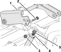
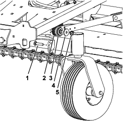
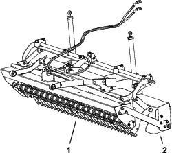
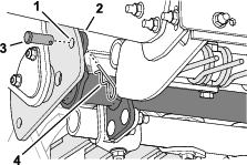
Install, but do not tighten, a push arm to the multi-tool using clamp plates and carriage bolts (3/8 x 1-3/4 inches) as shown in Figure 3.
-
Tighten the locknuts securing the push arms to 46 to 54 N∙m (34 to 40 ft lbs).
-
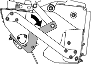
Rotate the push arm up and align the bushing with the parallel mounting tab on the underside of the frame.
-
Assemble the push-arm end to the mounting tab on the underside of the frame with the carriage bolt, thrust washer, and locknut and tighten the locknut to 112 to 136 N∙m (83 to 101 ft-lb).
-
Repeat this procedure for the push arm at the other side of the machine.
Connecting the Track Rod
Parts needed for this procedure:
| Carriage bolt (1/2 x 2-1/2 inches) | 1 |
| Thrust washer | 1 |
| Locknut (1/2 inch) | 1 |
-
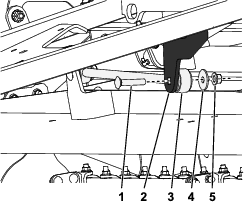
Rotate the track rod up and align the bushing with the mounting tab on the underside of the frame.
-
Assemble the track-rod end to the perpendicular mounting tab on the underside of the frame with the carriage bolt, thrust washer, and locknut and tighten the locknut to 112 to 136 N∙m (83 to 101 ft-lb).
Installing the Hydraulic Hoses
Parts needed for this procedure:
| Rubber grommet | 2 |
| Straight orifice fitting | 2 |
-
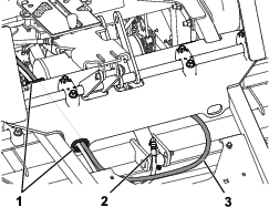
Install the rubber grommets to the holes on the right side of the lift pivot bracket.
-
Route the hydraulic hoses from the multi-tool cylinder toward the controls through the grommets.
Note: Route the hydraulic hoses away from any sharp, hot, or moving parts; ensure that the hoses do not twist around each other.
-
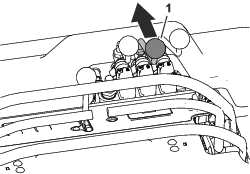
Remove the hood, refer to the machine Operator’s Manual.
-
Remove a hydraulic plug from the front of the control-valve manifold.
Note: Removing the plug may allow hydraulic fluid to flow from the manifold; align a drain pan beneath to catch any spilled fluid.
-
Install a straight orifice fitting to the manifold where the plug used to be; repeat this for the other plug.
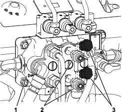
-
Tighten the straight orifice fitting to 81.3 to 89.5 N∙m (60 to 66 ft-lb).
-
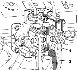
Remove the plug from the upper straight orifice fitting and secure the hose from the bottom of the multi-tool cylinder to the upper fitting.
-
Remove the plug from the lower straight orifice fitting and secure the hose from the top of the multi-tool cylinder to the lower fitting.
Note: If you feel or see any twists in the hoses, loosen the fittings, allow the hoses to return to a neutral position, then tighten the fittings.
-
Tighten the hose fittings 40.6 to 44.7 N∙m (30 to 33 ft-lb).
Completing the Installation
Parts needed for this procedure:
| Control handle assembly | 1 |
| Hex nut (M10) | 1 |
Warning
Hydraulic fluid escaping under pressure can penetrate skin and cause injury.
-
Seek immediate medical attention if fluid is injected into skin. Injected fluid must be surgically removed within a few hours by a doctor.
-
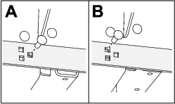
Ensure that all hydraulic-fluid hoses and lines are in good condition and all hydraulic connections and fittings are tight before applying pressure to the hydraulic system.
-
Keep your body and hands away from pinhole leaks or nozzles that eject high-pressure hydraulic fluid.
-
Use cardboard or paper to find hydraulic leaks.
-
Safely relieve all pressure in the hydraulic system before performing any work on the hydraulic system.
-
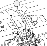
Install the handle assembly to the control valve manifold with the hex nut (M10) as shown in Figure 9.
-
Ensure that all fittings and hydraulic connections are secured and tightened.
-
Ensure that the hose coverings are covering both ends of the hoses so that no parts of the hoses are exposed to the operator.
-
Remove the pallet from the multi-tool attachment.
-
Install the hood; refer to your Operator’s Manual.
-
Ensure that the hydraulic pump bypass valves are in the operation position; refer to your Operator’s Manual.
-
Check the hydraulic fluid level and replenish it as required; refer to your Operator’s Manual.
-
Start the machine and allow the hydraulic system to pressurize.
-
Shut off the engine and check the hydraulic tubes, hoses, and fittings for leaks. Check the hydraulic fluid level again and replenish it as required; refer to your Operator’s Manual.
Note: Repair all leaks before operating the machine.
-
Start the machine and check that the control operates correctly; pushing forward on the control should pivot multi-tool toward the operator, and pulling back on the control should pivot the multi-tool away from the operator.
Note: If this operation is reversed, ensure that your hydraulic connections are installed as described in these instructions.
-
Calibrate the stop height of the multi-tool attachment and ensure that it is level; refer to your Operator’s Manual.
Product Overview
|
Length |
91.5 cm (36 inches) |
|
Width |
172.7 cm (68 inches) |
|
Height |
51.7 cm (21 inches) |
|
Net weight |
213.2 kg (470 lb) |
Attachments/Accessories
A selection of Toro approved attachments and accessories is available for use with the machine to enhance and expand its capabilities. Contact your Authorized Service Dealer or authorized Toro distributor or go to www.Toro.com for a list of all approved attachments and accessories.
To ensure optimum performance and continued safety certification of the machine, use only genuine Toro replacement parts and accessories. Replacement parts and accessories made by other manufacturers could be dangerous, and such use could void the product warranty.
Operation
Adjusting the Tilt Angle of the Mid-Mount Attachment
Tilting the Mid-Mount Attachment Backward
Move the mid-mount attachment tilt control forward to rotate the tine-engagement angle backward.
Tilting the Mid-Mount Attachment Forward
Move the mid-mount attachment tilt control back to rotate the tine-engagement angle forward.

Selecting the Multi-Tool
-
Fully lift the multi-tool carrier; refer to the Operator’s Manual for your machine.
-
Rotate the multi-tool carrier backward until you can fully access the clevis pin and the 13 mm (1/2 inch) hole in the angle-select plate; refer to Tilting the Mid-Mount Attachment Backward.
-
Remove the hairpin and clevis pin that secures the multi-tool arm to the angle-select plate (Figure 14).
-
Repeat step 3 at the other side of the machine.
Caution
The multi-tool arm rotates freely when the clevis pins are removed; your hands or fingers could get pinched and injured if they are caught between the multi-tool arm and the angle-select plate.
-
Keep your hands and fingers clear of the area behind the angle-select plate while rotating the multi-tool.
-
Secure the multi-tool arm from movement before removing the second clevis pin.
-
-
Rotate the multi-tool arm to select a set of plow tines (Figure 15).
-
Align the hole in the multi-tool arm with the hole in the angle-select plate (Figure 16).
-
Secure the multi-tool arm to the angle-select plate with the clevis pin and hair pin.
-
Repeat step 8 at the other side of the machine.
-
Adjust the tilt of the multi-tool carrier as needed (Figure 17).
Using the Mid-Mount Attachment Stop
Use the stop pins and the mid-mount attachment stop to limit how far up or down you can position the multi-tool attachment, when transporting the machine, and when maintaining the multi-tool attachment; refer to the Operator’s Manual for your machine.
Adjusting the Grader and Box Blade Positions
The grader blade and the box blade positions are adjustable to account for wear and operator preference.
The grader blade has 3 height positions; remove the 4 carriage bolts and locknuts securing the grader blade and adjust it up or down Figure 19.
The height and angle of the box blades are adjustable; loosen the locknuts securing box blade to the multi-tool; repeat this for the other side Figure 20.