Installation
Note: Determine the left and right sides of the machine from the normal operating position.
Preparing the Machine
-
Park the machine on a level surface.
-
Disengage the blade-control switch.
-
Move the motion-control levers outward to the NEUTRAL-LOCK position.
-
Engage the parking brake.
-
Shut off the engine and remove the key.
-
Disconnect the negative battery cable.
Warning
Incorrect battery cable routing could damage the machine and cables, causing sparks. Sparks can cause the battery gases to explode, resulting in personal injury.
-
Always disconnect the negative (black) battery cable before disconnecting the positive (red) cable.
-
Always connect the positive (red) battery cable before connecting the negative (black) cable.
-
-
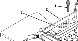
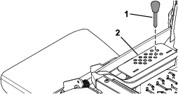
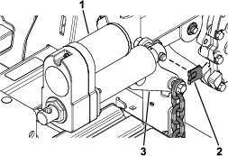
Push the deck-lift pedal fully forward to lock the mower deck in the TRANSPORT position (Figure 1).
-
Support the mower deck using 4x4 blocks of wood.
-
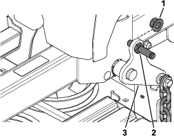
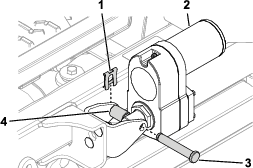
Remove the height-of-cut pin from the height-of-cut bracket (Figure 2).
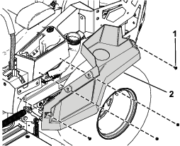
Removing the Left Side Pod and Fuel-Tank Cap
Danger
Under certain conditions, fuel and fuel vapors are highly flammable and explosive. A fire or explosion from fuel can burn you and others and can cause property damage.
-
Fill the fuel tank outdoors, in an open area, when the engine is off and cold. Wipe up any spilled fuel.
-
Do not fill the fuel tank completely full. Add fuel to the fuel tank until the level is 25 mm (1 inch) below the top of the tank, not the filler neck. This empty space in the tank allows the fuel to expand.
-
Never smoke when handling fuel, and stay away from an open flame or a spark that could ignite fuel fumes.
-
Store fuel in a clean, safety-approved container and keep the cap in place.
-
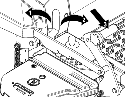
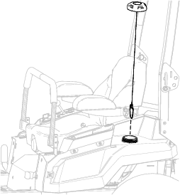
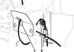
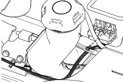
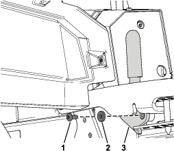
Remove the fuel-tank cap from the left side pod (Figure 3).
Retain the fuel-tank cap for later installation.
-
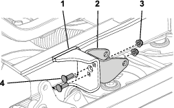
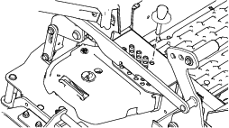
Remove the 4 shoulder screws securing the left side pod and remove the left side pod (Figure 4).
Retain the left side pod and 4 shoulder screws for later installation.
-
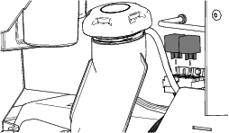
Install the fuel-tank cap (Figure 3).
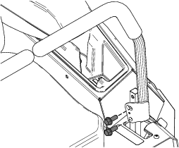
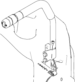
Removing the Existing Left Motion-Control Lever
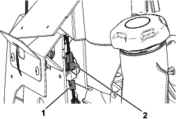
Remove the 2 flange-head bolts (3/8 x 1 inch) securing the existing left motion-control lever and remove the left motion-control lever (Figure 5).
Retain the 2 flange-head bolts (3/8 x 1 inch) for later installation.
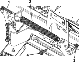
Removing the Deck-Lift Spring
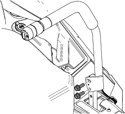
Installing the New Left Motion-Control Lever
Parts needed for this procedure:
| Left motion-control lever | 1 |
-
Secure the new left motion-control lever using the previously removed 2 flange-head bolts (3/8 x 1 inch) as shown in Figure 7.
-
Route the wire harness on the motion-control lever through the hole in the left cover plate (Figure 8).
-
Secure the wire harness to the notch in the left motion-control plate (Figure 8).
Installing the Actuator Mount and Rear-Lift Hardware
Parts needed for this procedure:
| Pivot pin | 1 |
| Locknut (1/2 inch) | 1 |
| Actuator mount | 1 |
| Carriage bolt (5/16 x 1 inch) | 2 |
| Locknut (5/16 inch) | 2 |
Routing the Wire Harness and Installing the Relays
Parts needed for this procedure:
| Deck-lift wire harness | 1 |
| Push-mount fastener | 1 |
| Relay | 2 |
| Taptite screw | 1 |
| P-clamp (Z Master 2000 only) | 1 |
Z Master 2000
Refer to the following figure for how to route the wire harness.
-
Route the wire harness through the opening in the p-clamp.
-
Route the wire harness along the left side of the machine.
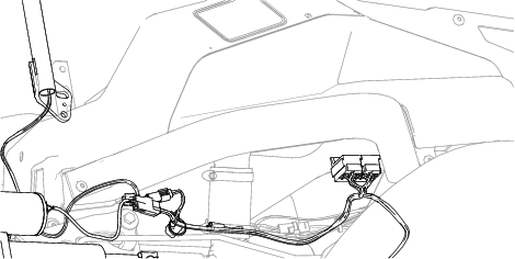
-
Secure the wire harness to the left pod near the relays using the taptite screw.
-
Install the 2 relays.
-
Remove the screw from the left pod.
Note: Retain the screw.
-
Secure the p-clamp to the left pod using the previously-removed screw.
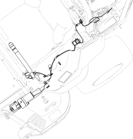
Z Master 4000
-
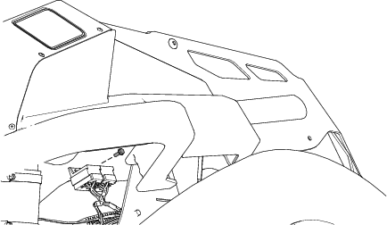
Install the front push-mount fastener into the parking-brake lever bracket (Figure 17).
Note: The rear push-mount fastener is already installed.
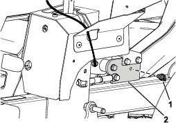
-
Route the wire harness (Figure 18) along the left side of the frame, and through the push-mount fastener that you installed in step 1.
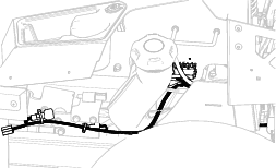
-
Install the second push-mount fastener into the rear fuel-tank bracket (Figure 19).
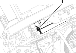
-
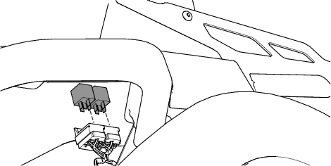
Secure the wire harness near the relays using the taptite screw (Figure 20).
-
Install the 2 relays (Figure 21).
Install the Left Side Pod and Fuel-Tank Cap
Connecting the Wire Harness
-
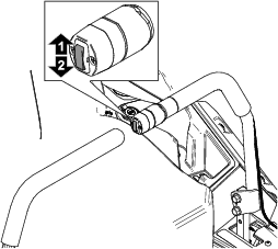
Connect the kit wire harness to the machine wire harness connector labeled .
-
Connect the kit wire harness connector to the new left motion-control lever connector (Figure 22).
-
Connect the kit wire harness to the actuator.
-
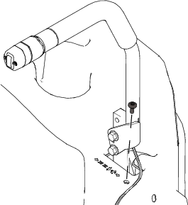
Pull the boot cover off the positive battery terminal.
-
Remove the nut from the positive battery terminal and install the kit wire harness positive terminal ring onto the bolt (Figure 23).
-
Secure the positive terminal ring using the previously removed nut (Figure 23).
-
Install the boot cover over the positive battery terminal.
-
Remove the nut from the negative battery terminal and install the kit wire harness negative terminal ring onto the bolt (Figure 23).
-
Secure the negative terminal ring using the previously removed nut (Figure 23).
Installing the Actuator
Parts needed for this procedure:
| Actuator | 1 |
| Pin clip | 2 |
| Aluminum spacer | 1 |
| Clevis pin | 1 |
-
Secure the actuator to the rear deck-lift arm using the pin clip (Figure 24).
-
Rotate the actuator upward and align the actuator with the holes in the actuator mount.
If the holes do not align, turn the machine on, and carefully press the deck-lift switch on the motion-control lever up or down until the holes align.
-
Secure the actuator to the actuator mount using the clevis pin, the aluminum spacer, and the pin clip as shown in Figure 25.
Removing the Transport Lock
-
Push the deck-lift switch upward until you hear a ratcheting sound or clicking sound from the actuator.
-
Turn off the machine.
-
Remove the bolt, washer, and transport lock (Figure 26).
Checking the Mower-Deck Height of Cut and Rake
Refer to the Adjusting the Side-to-Side Leveling and the Blade Slope procedure in the Operator's Manual.
Operation
Adjusting the Mower Deck to Transport Height
-
Push up on the deck-lift switch (Figure 28) until the deck is fully raised.
-
Insert the height-of-cut pin into the 127 mm (5 inches) height-of-cut position of the bracket (Figure 27).
-
Push down on the deck-lift switch until the height-of-cut linkage slightly contacts the height-of-cut pin.
Note: Too much contact between the height-of-cut linkage and height-of-cut pin can negatively affect the mower deck height of cut and leveling.
Adjusting the Height of Cut
-
Push up on the deck-lift switch (Figure 28).
-
Select a hole in the height-of-cut bracket corresponding to the height of cut desired, and insert the pin (Figure 29).
-
Push down on the deck-lift switch until the height-of-cut linkage slightly contacts the height-of-cut pin (Figure 29).
Note: Too much contact between the height-of-cut linkage and height-of-cut pin can negatively affect the mower deck height of cut and leveling.