Introduction

The Versa Vac is to be used in conjunction with the combination deck or finger deck. The machine is intended to be used by professional, hired operators in commercial applications. The machine is designed to dethatch, renovate, and remove debris from large turf areas in 1 pass. Using this product for purposes other than its intended use could prove dangerous to you and bystanders.

Read this information carefully to learn how to operate and maintain your product properly and to avoid injury and product damage. You are responsible for operating the product properly and safely.

Visit www.Toro.com for product safety and operation training materials, accessory information, help finding a dealer, or to register your product.

Whenever you need service, genuine the manufacturer parts, or additional information, contact an Authorized Service Dealer or Toro Customer Service and have the model and serial numbers of your product ready. Write the numbers in the space provided.

Safety-Alert Symbol

The safety-alert symbol (Figure 1) shown in this manual and on the machine identifies important safety messages that you must follow to prevent accidents.

g000502

The safety-alert symbol appears above information that alerts you to unsafe actions or situations and is followed by the word DANGER, WARNING, or CAUTION.

DANGER indicates an imminently hazardous situation which, if not avoided, will result in death or serious injury.

WARNING indicates a potentially hazardous situation which, if not avoided, could result in death or serious injury.

CAUTION indicates a potentially hazardous situation which, if not avoided, may result in minor or moderate injury.

This manual uses two other words to highlight information. Important calls attention to special mechanical information and Note emphasizes general information worthy of special attention.

This product complies with all relevant European directives. For details, please see the separate product specific Declaration of Conformity (DOC) sheet.

Warning

CALIFORNIA

Proposition 65 Warning

Use of this product may cause exposure to chemicals known to the State of California to cause cancer, birth defects, or other reproductive harm.

Safety

General Safety

This product is capable of amputating hands and feet and of throwing objects. Always follow all safety instructions to avoid serious personal injury.

  • Read and understand the contents of this Operator’s Manual before using the machine.

  • Do not put your hands or feet near moving components of the machine.

  • Use your full attention while operating the machine. Do not engage in any activity that causes distractions; otherwise, injury or property damage may occur.

  • Do not operate the machine without all guards and other safety protective devices in place and functioning properly on the machine.

  • Keep clear of any discharge opening. Keep bystanders and pets away from the machine.

  • Keep children, bystanders, and pets out of the operating area. Never allow children to operate the machine.

  • Always shut off the engine of the traction unit, remove the key (if equipped), wait for all moving parts to stop, and allow the machine to cool before adjusting, servicing, cleaning, or storing the machine.

Improperly using or maintaining this machine can result in injury. To reduce the potential for injury, comply with these safety instructions and always pay attention to the safety-alert symbol Graphic, which means Caution, Warning, or Danger—personal safety instruction. Failure to comply with these instructions may result in personal injury or death.

Safety and Instructional Decals

Graphic

Safety decals and instructions are easily visible to the operator and are located near any area of potential danger. Replace any decal that is damaged or missing.

decal105-0627
decal105-0628
decal105-0668
decal105-0669
decal106-0162
decal93-6674
decal105-4587
decal105-0698
decal117-4979
decal106-0163
decal110-7506
decal106-0166
decal106-0167
decal106-0183
decal133-8061
decal138-9038

Setup

Caution

Without the proper amount of ballast in the tires, the traction unit may become unstable and cause bodily injury.

Make sure that the front of the traction unit is equipped with the proper amount of ballast; refer to the traction unit Operator’s Manual for ballast requirements.

Connecting the Machine to the Traction Unit

Parts needed for this procedure:

Jack1

Refer to Connecting the Machine to the Traction Unit.

Adjusting the PTO Shaft Length

Parts needed for this procedure:

PTO shaft1

A long PTO shaft is supplied with the machine to accommodate traction units with larger PTO shaft variations. For most traction units, this shaft is too long and must be cut to the correct length, or damage may result.

  1. Measure the distance from the lock groove of the traction unit PTO shaft to the lock groove of the machine impeller input shaft.

    Note: Record this dimension.

  2. Fully collapse the PTO shaft and measure the distance between the lock pin collars.

    Note: Record this dimension.

  3. When attached to the machine, the 2 halves of the PTO shaft must have at least 37 mm (1-1/2 inches) of additional clearance to collapse at its shortest length (Figure 2).

    Note: If the dimension in Step 1 is not at least 37 mm (1-1/2 inches) greater than the dimension in Step 2, the PTO shaft is too long; proceed to Step 4. If there is enough clearance to allow the PTO shaft to collapse, proceed to Step 9.

    g287903
  4. Use the following calculation to establish how much shorter the shaft must be, when connected, to ensure a clearance of 37 mm (1-1/2 inches):

    1. Subtract the dimension recorded in Step 1 from the dimension recorded in Step 2.

      Note: Record this dimension.

    2. Add 37 mm (1-1/2 inches) to the result of Step 1.

      Important: You must shorten the PTO shaft by this amount.

  5. Using a hacksaw, shorten the guards and the steel tubes by the length calculated in step 2.

    Important: Shorten both halves of the PTO shaft and PTO shaft shields by this length.

  6. Deburr the ends of the steel tubes internally and externally.

  7. Remove all debris from the tube sections.

  8. Grease the steel tubes liberally.

  9. Assemble the PTO shaft and secure it to the machine and traction unit.

  10. Measure the length of the exposed shaft at its shortest length; if it is not at least 37 mm (1-1/2 inches), repeat the procedure.

Connecting the PTO Shaft

Connect the PTO shaft; refer to Connecting the PTO Shaft.

Applying the Entanglement Decal

CE Machines

Parts needed for this procedure:

CE entanglement decal4

Important: This procedure is required for all CE countries and anywhere English is not commonly spoken.

  1. Rotate the shaft guard to access the existing entanglement decal (Figure 3).

    g273965
  2. Clean the existing entanglement decal and the guard area surrounding the decal.

  3. Remove the backing from the CE entanglement decal.

  4. Place the CE entanglement decal over the existing entanglement decal (Figure 3).

  5. Repeat steps 1 through 4 for the 3 other shaft guards.

Installing the Auxiliary Control (Optional)

Parts needed for this procedure:

Auxiliary control lever1

Important: The auxiliary control lever is shipped loose to prevent accidental engagement of the unused hydraulic circuit. Do not install or operate the auxiliary control lever unless the combination deck is installed.

  1. Remove the control lever cover.

  2. Remove the 2 cotter pins from the control valve spool.

  3. Mount the auxiliary control lever to the valve spool with the cotter pins.

  4. Install the control lever cover.

Greasing the Machine

Grease the machine; refer to Lubricating the Machine.

Product Overview

g027357

Trailer Lift Control

Used to dump the trailer box (Figure 4). The up position raises the box and opens the door, and the down position lowers the box and closes the door.

Deck Lift Control

Used to raise and lower the primary deck (Figure 4). The up position raises the deck, and the down position lowers the deck.

Brush Control

Used to operate the rotating finger deck (sold separately). The up position starts the deck, and the down position stops the deck (Figure 4).

Auxiliary Control

Used to operate the combination deck (sold separately). The up position starts the deck, and the down position stops the deck (Figure 4).

Important: The auxiliary control lever is shipped loose to prevent accidental engagement of the unused hydraulic circuit. Do not install or operate the auxiliary control lever unless the combination deck is installed.

Safety Latch

Remove only the safety latch when operating the combination deck (Figure 4).

Traction Unit PTO

The vacuum fan on the machine runs as soon as you engage the PTO (Figure 4). You can engage the finger and combination decks by using the hydraulic controls on the machine.

Important: Always engage the traction unit PTO gently at a low engine speed. Sudden engagement of the traction unit PTO at a high engine speed will likely damage the drive line components.

Operation

Note: Determine the left and right sides of the machine from the normal operating position.

Caution

If you leave the key in the traction unit ignition switch, someone could accidently start the engine and seriously injure you or other bystanders.

Remove the key from the traction unit ignition before you do any maintenance.

Before Operation

Before Operation Safety

General Safety

  • Do not allow children or untrained people to operate or service the machine. Local regulations may restrict the age of the operator. The owner is responsible for training all operators and mechanics.

  • Become familiar with the safe operation of the equipment, operator controls, and safety signs.

  • Know how to stop the machine and shut off the engine quickly.

  • Do not operate the machine without all guards and other safety protective devices in place and functioning properly on the machine.

  • Ensure that all hydraulic line connectors are tight, and all hydraulic hoses and lines are in good condition before applying pressure to the system.

  • Before operating, always inspect the machine to ensure that the flail knives are in good working condition. Replace worn or damaged knives.

  • Inspect the area where you will use the machine and remove all objects that the machine could strike.

  • Ensure that your traction unit is suitable for use with an implement of this weight by checking with your traction unit supplier or manufacturer.

  • The traction unit must have the proper wheel base and tread width and be equipped with a roll bar and seat belt to operate safely on hilly terrain. The normal operating speed is 10 km/h (6 mph) but will vary with terrain and debris being picked up. The maximum transport speed is 24 km/h (15 mph) with slower speeds required on hilly terrain. Refer to the traction unit Operator’s Manual for information or traction unit service agency if you have any questions on safe operation.

  • The brakes of the tow traction unit must have the capacity to stop the machine with machine fully loaded and traveling at the maximum recommended transport speed.

  • The power take-off drive of the machine requires a traction unit with operating speeds of 540 rpm and output power of 32 hp or higher. Do not exceed the 540 rpm speed.

Connecting the Machine to the Traction Unit

  1. Position the machine on a flat, level surface.

  2. Insert the jack onto the frame pin and secure it with the pin (Figure 5).

    g027352
  3. Adjust the jack height until the machine frame is parallel with the ground.

  4. Back the traction unit up to the machine.

  5. Adjust the machine hitch clevis to the same level as the traction unit hitch as follows:

    1. Remove the bolts and locknuts that secure the hitch clevis (Figure 6) to the machine frame.

      g027353
    2. Raise or lower the hitch clevis to the position approximately level with the traction unit hitch.

    3. Secure it with the bolts and locknuts that were previously removed.

  6. Connect the traction unit hitch to the machine clevis hitch with the hitch pin and clevis.

  7. Remove the jack pin, rotate the jack upward to the storage position.

Connecting the PTO Shaft

  1. Connect the PTO shaft to the machine impeller input shaft.

  2. Connect the PTO shaft to the rear traction unit PTO shaft.

  3. Slide the PTO shaft forward as far as it will go.

  4. Press the pin to secure the PTO shaft in place.

    Note: Slide the PTO shaft back and forth to ensure that it is properly locked.

  5. Connect the shield safety chain to the traction unit (Figure 7).

    Note: Ensure that the chain remains slack when you turn the traction unit.

    g027355

    Caution

    If the shield chains are not connected, the shields could rotate during operation and cause bodily injury.

    Keep all PTO shields in place and connect the shield chain to the traction unit or PTO shields.

Performing Daily Maintenance

Perform the following procedures daily before operating the machine:

During Operation

During Operation Safety

General Safety

  • The owner/operator can prevent and is responsible for accidents that may cause personal injury or property damage.

  • Wear appropriate clothing, including eye protection; slip-resistant, substantial footwear; long pants; and hearing protection. Tie back long hair and do not wear loose clothing or loose jewelry.

  • Use your full attention while operating the machine. Do not engage in any activity that causes distractions; otherwise, injury or property damage may occur.

  • Do not operate the machine when tired, ill, or under the influence of alcohol or drugs.

  • Do not carry passengers on the machine and keep bystanders and pets away from the machine during operation..

  • The brush, rubber fingers, flail, and vacuum of the machine may pick up and propel debris and small objects in its path during operation; keep bystanders and pets away from the machine during operation.

  • Always disengage the PTO, shut off the engine of the traction unit, remove the key, and wait for all moving parts to stop before leaving the operator’s position.

  • Do not step over the PTO shaft to get to the other side of the machine. Walk around the machine.

  • Always stand away from the rear of the machine when opening the rear door.

  • Operate the machine only in good visibility to avoid holes or hidden hazards.

  • Keep your hands and feet away from the flail knives.

  • Look behind and down before backing up to be sure of a clear path.

  • Stop the machine, shut off the engine, wait for all moving parts to stop, and inspect the machine after striking an object or if there is an abnormal vibration in the machine. Make all necessary repairs before resuming operation.

  • Always maintain proper traction unit tire pressure.

  • Reduce speed on rough surfaces.

  • For all PTO shaft steel parts (tubes, bearings, joints, etc.) disassembly or repairs, it is highly advisable to contact your authorized Toro distributor. Removal of components for repairs and reassembly may damage some parts if not performed with special tools by trained technicians.

  • The PTO shaft must not be used without the guards supplied.

Dumping Safety

  • Moving the rear door and dumping debris can cause serious injury. Stay clear of the machine while it is backing up or dumping.

  • Keep bystanders away from the machine when operating to dump debris or when opening and closing the rear door.

  • Under rare circumstances, wet, compressed grass clippings may generate heat. Always empty the machine before storing it.

  • To avoid the risk of electrical shock, dump the machine only in areas that are clear of overhead wires and other obstructions.

  • Never dump the machine on a slope; always dump the machine on level ground.

Slope Safety

  • Review the traction unit specifications to ensure that you do not exceed its slope capabilities.

  • Slopes are a major factor related to loss of control and rollover accidents, which can result in severe injury or death. You are responsible for safe slope operation. Operating the machine on any slope requires extra caution.

  • Evaluate the site conditions to determine if the slope is safe for machine operation including surveying the site. Always use common sense and good judgment when performing this survey.

  • Review the slope instructions listed below for operating the machine on slopes and review the conditions to determine whether you can operate the machine in the conditions on that day and at that site. Changes in the terrain can result in a change in slope operation for the machine.

  • Avoid starting, stopping, or turning the machine on slopes. Avoid making sudden changes in speed or direction. Make turns slowly and gradually.

  • Do not operate a machine under any conditions where traction, steering, or stability is in question.

  • Remove or mark obstructions such as ditches, holes, ruts, bumps, rocks, or other hidden hazards. Tall grass can hide obstructions. Uneven terrain could overturn the machine.

  • Be aware that operating the machine on wet grass, across slopes, or downhill may cause the machine to lose traction. Loss of traction to the drive wheels may result in sliding and a loss of braking and steering.

  • Use extreme caution when operating the machine near drop offs, ditches, embankments, water hazards, or other hazards. The machine could suddenly roll over if a wheel goes over the edge or the edge caves in. Establish a safety area between the machine and any hazard.

Operating the Traction Unit Hydraulics

All hydraulic machine functions are controlled by the hydraulic valve that is located at the front of the machine. The PTO must be running while the machine is in use. This is what creates the continuous fluid flow throughout the machine.

Important: Never move a hydraulic lever rapidly between the up and down positions. Forcing a hydraulic motor to reverse direction instantly may severely damage it. If any part of the machine becomes plugged or material does not want to flow, shut the machine off completely and manually remove the blockage.

Note: You can adjust the hydraulic control console for comfort by loosening the lever on the frame behind the controls, adjusting the control console fore or aft, and tightening the lever.

Operating the Machine

  1. Start the traction unit and run it at a low rpm.

  2. Engage the PTO while the engine is at idle speed.

  3. Increase the PTO speed to 540 rpm.

  4. Before starting operation, survey the area to determine the best direction to go.

  5. Drive the traction unit forward and tow the machine to the job site.

    Note: To maintain a straight line when operating, sight off an object in the foreground.Always try to make a long, continuous pass with a slight overlap on the return pass.

Important: Shut off the traction unit engine, engage the parking brake, remove the key, and wait for all moving parts to stop before checking for fluid leaks, loose parts, damage or wear.

After Operation

After Operation Safety

General Safety

  • Keep all parts of the machine in good working condition and all hardware tightened.

  • Replace all worn, damaged, or missing decals.

  • Empty the machine, park on a level surface, and chock the wheels before disconnecting the machine from the traction unit.

Removing the Machine from the Traction Unit

  1. Park the machine and traction unit on a level surface, disengage the PTO, engage the parking brake, shut off the engine, remove the key, and wait for the engine and all moving parts to stop before leaving the operator’s seat.

  2. Chock the wheels.

  3. Remove the pin that secures the jack to the frame pin and rotate the jack down into vertical position.

  4. Secure the jack to the frame pin and adjust the jack to support the machine.

    Warning

    The machine is very heavy. Do not disconnect the machine without first putting down the jack.

    Personal injury could occur if the hitch drops.

  5. Disconnect the safety shield chains from the traction unit or PTO shield. Secure the end of the chain to the impeller side of the PTO shaft to prevent the PTO shaft from coming apart.

  6. Disconnect the PTO shaft from the traction unit output shaft.

  7. Slide the PTO shaft back and remove it from the traction unit.

  8. Remove the hitch pin and clevis.

  9. Move the traction unit away from the machine.

Transporting the Machine

You can transport the machine to work sites using any traction unit with a draw-bar-type hitch. The machine is not designed for highway towing.

  • The wide flotation turf tires are not for highway use and are only for speeds below 24 km/h (15 mph). At speeds above 24 km/h (15 mph), the tires will lose their tread, cause harm to the operator, and damage the equipment.

  • Ensure that the deck is raised and the casters cannot contact the ground during transport. Also, ensure that the cylinder lock bar (Figure 8) is in place to prevent the lift cylinder from compressing during transport.

    g027358
  • Use adequate lighting and braking, a retainer type hitch pin, and a safety chain while towing.

  • Make sure that the tires are properly inflated.

Maintenance

Recommended Maintenance Schedule(s)

Maintenance Service IntervalMaintenance Procedure
After the first 2 hours
  • Torque the wheel nuts.
  • After the first 10 hours
  • Torque the wheel nuts.
  • After the first 20 hours
  • Check/adjust the impeller belt tension.
  • Before each use or daily
  • Grease the fan shaft bearings.
  • Check the tire air pressure.
  • Check the hydraulic lines and hoses.
  • Check the hydraulic fluid level.
  • Every 100 hours
  • Grease the drive shaft.
  • Every 200 hours
  • Torque the wheel nuts.
  • Every 800 hours
  • If you are not using the recommended hydraulic fluid or have ever filled the reservoir with an alternative fluid, change the hydraulic fluid.
  • If you are not using the recommended hydraulic fluid or have ever filled the reservoir with an alternative fluid, change the hydraulic filter.
  • Every 1,000 hours
  • If you are using the recommended hydraulic fluid, replace the hydraulic filter.
  • Every 2,000 hours
  • If you are using the recommended hydraulic fluid, change the hydraulic fluid and filter.
  • Monthly
  • Check/adjust the impeller belt tension.
  • Maintenance Safety

    • Before adjusting, cleaning, servicing, or leaving the machine, do the following:

      • Position the machine on a level surface.

      • Disengage the PTO.

      • Ensure that the traction unit is in neutral.

      • Engage the traction unit parking brake.

      • Shut off the engine of the traction unit and remove the key.

      • Wait for all moving parts to stop.

      • Allow machine components to cool before performing maintenance.

    • Perform only those maintenance instructions described in this manual. If major repairs are ever needed or assistance is desired, contact an authorized Toro distributor.

    • Ensure that the machine is in safe operating condition by keeping hardware tightened.

    • If possible, do not perform maintenance while the traction unit engine is running. Keep away from moving parts.

    • Do not check or adjust the belt tension when the traction unit engine is running.

    • Carefully release pressure from components with stored energy.

    • Support the machine with blocks whenever you raise it. Do not rely on a hydraulic system to support the machine.

    • Ensure that all guards are installed after maintaining or adjusting the machine.

    Lubricating the Machine

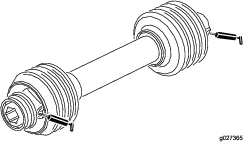
    Greasing the Fan Shaft Bearings

    Maintenance Service IntervalMaintenance Procedure
    Before each use or daily
  • Grease the fan shaft bearings.
    1. Remove the drive shield from over the pulley assemblies (Figure 14).

    2. Grease the fittings on the fan shaft bearings as illustrated in Figure 10 with No. 2 lithium grease.

      g027364

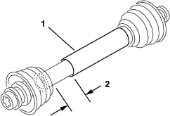
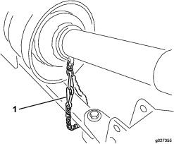
    Greasing the Drive Shaft

    Maintenance Service IntervalMaintenance Procedure
    Every 100 hours
  • Grease the drive shaft.
  • Grease the 2 drive shaft fittings as illustrated in Figure 10 with No. 2 lithium grease.

    g027365

    Checking the Tire Air Pressure

    Maintenance Service IntervalMaintenance Procedure
    Before each use or daily
  • Check the tire air pressure.
  • Important: Maintain the same air pressure in both tires to ensure proper machine performance. Do not under inflate the tires.

    1. Check the air pressure in the tires.

      You should measure 124 kPa (18 psi).

    2. If the air pressure is too high or too low, adjust the air pressure until you measure 124 kPa (18 psi).

    Checking the Torque of the Wheel Nuts

    Maintenance Service IntervalMaintenance Procedure
    After the first 2 hours
  • Torque the wheel nuts.
  • After the first 10 hours
  • Torque the wheel nuts.
  • Every 200 hours
  • Torque the wheel nuts.
  • Warning

    Failure to maintain the proper torque of the wheel nuts could result in failure or loss of the wheel and may result in personal injury.

    Ensure that the wheel nuts are properly tightened before operating the machine.

    Torque the wheel nuts to 115 to 136 N⋅m (85 to 100 ft-lb) in a crossing pattern (Figure 11).

    g272937

    Hydraulic System Safety

    • Seek immediate medical attention if fluid is injected into skin. Injected fluid must be surgically removed within a few hours by a doctor.

    • Ensure that all hydraulic-fluid hoses and lines are in good condition and all hydraulic connections and fittings are tight before applying pressure to the hydraulic system.

    • Keep your body and hands away from pinhole leaks or nozzles that eject high-pressure hydraulic fluid.

    • Use cardboard or paper to find hydraulic leaks.

    • Before disconnecting or performing any work on the hydraulic system, lower the implement to the ground and shut off the engine to relieve all pressure in the system.

    • To ensure safe, optimal performance of the machine, use only genuine Toro replacement parts. Replacement parts made by other manufacturers could be dangerous, and such use could void the product warranty.

    Checking the Hydraulic Lines and Hoses

    Maintenance Service IntervalMaintenance Procedure
    Before each use or daily
  • Check the hydraulic lines and hoses.
  • Check the hydraulic lines and hoses for leaks, kinked lines, loose mounting supports, wear, loose fittings, weather, deterioration, and chemical deterioration. Make all necessary repairs before operating the machine.

    Warning

    Hydraulic fluid escaping under pressure can penetrate skin and cause injury.

    • Ensure that all hydraulic fluid hoses and lines are in good condition and all hydraulic connections and fittings are tight before applying pressure to the hydraulic system.

    • Keep body and hands away from pin-hole leaks or nozzles that eject high pressure hydraulic fluid.

    • Use cardboard or paper to find hydraulic leaks.

    • Safely relieve all pressure in the hydraulic system before performing any work on the hydraulic system.

    • Seek immediate medical attention if fluid is injected into skin.

    Servicing the Hydraulic System

    Hydraulic Fluid Specifications

    The reservoir is filled at the factory with high-quality hydraulic fluid. Check the level of the hydraulic fluid before you first start the engine and daily thereafter; refer to Checking the Hydraulic Fluid Level.

    Recommended replacement fluid: the manufacturer PX Extended Life Hydraulic Fluid; available in 19 L (5 US gallon) pails or 208 L (55 US gallon) drums.

    Note: A machine using the recommended replacement fluid requires less frequent fluid and filter changes.

    Alternative fluids: If the manufacturer PX Extended Life Hydraulic Fluid is not available, you may use another conventional, petroleum-based hydraulic fluid having specifications that fall within the listed range for all the following material properties and that it meets industry standards. Do not use synthetic fluid. Consult with your lubricant distributor to identify a satisfactory product.

    Note: the manufacturer does not assume responsibility for damage caused by improper substitutions, so use products only from reputable manufacturers who will stand behind their recommendation.

    High Viscosity Index/Low Pour Point Anti-wear Hydraulic Fluid, ISO VG 46

    Material Properties: 
     Viscosity, ASTM D445cSt @ 40°C (104°F) 44 to 48
     Viscosity Index ASTM D2270140 or higher
     Pour Point, ASTM D97-37°C to -45°C (-34°F to -49°F)
     Industry Specifications:Eaton Vickers 694 (I-286-S, M-2950-S/35VQ25 or M-2952-S)

    Note: Many hydraulic fluids are almost colorless, making it difficult to spot leaks. A red dye additive for the hydraulic fluid is available in 20 ml (0.67 fl oz) bottles. A bottle is sufficient for 15 to 22 L (4 to 6 US gallons) of hydraulic fluid. Order Part No. 44-2500 from your authorized the manufacturer distributor.

    Checking the Hydraulic Fluid Level

    Maintenance Service IntervalMaintenance Procedure
    Before each use or daily
  • Check the hydraulic fluid level.
    1. Operate the machine so that the fluid is warm, park the machine on a level surface, and shut off the engine.

    2. Check the level of the fluid by viewing the sight gauge (Figure 12).

      You should see the fluid level is in the middle of the sight gauge.

      g027356
    3. If the fluid level is below the middle of the gauge, remove the cap from the hydraulic fluid reservoir and slowly add the specified hydraulic fluid until the level reaches the middle (maximum) of the sight gauge; refer to Hydraulic Fluid Specifications.

      Important: Do not over fill the reservoir; if you exceed the max fill line of the sight gauge you must remove the excess fluid; refer to Changing the Hydraulic Fluid.

      Important: To prevent hydraulic system contamination, clean the top of the hydraulic-fluid containers opening it. Ensure that the pour spout and the funnel are clean.

    4. Install the reservoir cap.

    Changing the Hydraulic Fluid

    Maintenance Service IntervalMaintenance Procedure
    Every 800 hours
  • If you are not using the recommended hydraulic fluid or have ever filled the reservoir with an alternative fluid, change the hydraulic fluid.
  • Every 2,000 hours
  • If you are using the recommended hydraulic fluid, change the hydraulic fluid and filter.
  • Reservoir capacity: approximately 38 L (10 US gallons)

    Important: If the fluid becomes contaminated, contact an authorized the manufacturer distributor. Contaminated fluid looks milky or black when compared to clean fluid.

    1. Turn the engine off.

    2. Disconnect the small hydraulic hose (case drain) from the bottom of the reservoir and let the hydraulic fluid flow into a drain pan.

      Note: Install and tighten the hose when the hydraulic fluid stops draining.

    3. Fill the reservoir with approximately 38 L (10 US gallons) of the specified hydraulic fluid; refer to Hydraulic Fluid Specifications.

      Important: Use only the hydraulic fluids specified. Other fluids could damage the system. To prevent over filling, do not fill if the fluid is cold. Do not over fill the reservoir with hydraulic fluid.

    4. Install the reservoir cap.

    5. Start the traction unit engine, use all the hydraulic controls to distribute the hydraulic fluid throughout the system, and check for leaks.

    6. Shut off the engine

    7. With the fluid warm, look into the sight gauge.

      Note: If the hydraulic fluid level is low, add enough fluid to raise the level to the middle (maximum) of the sight gauge.

    Replacing the Hydraulic Filter

    Maintenance Service IntervalMaintenance Procedure
    Every 800 hours
  • If you are not using the recommended hydraulic fluid or have ever filled the reservoir with an alternative fluid, change the hydraulic filter.
  • Every 1,000 hours
  • If you are using the recommended hydraulic fluid, replace the hydraulic filter.
  • Use only the the manufacturer replacement filter in the hydraulic system; refer to the Parts Catalog.

    Important: Use of any other filter may void the warranty on some components.

    1. Turn the traction unit engine off and remove the key from the ignition.

    2. Clean the area around the filter mounting area.

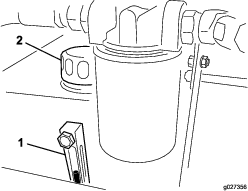
    3. Place a drain pan under the filter and remove the filter (Figure 13).

      g027366
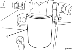
    4. Lubricate the new filter gasket and fill the filter with hydraulic fluid.

    5. Ensure that the filter mounting area is clean.

    6. Screw the filter on until the gasket contacts the mounting plate, then tighten the filter one–half turn.

    7. Start the traction unit engine and operate the hydraulic controls to purge air from the system.

    8. Shut off the engine and check the fluid level and for any leaks.

    Adjusting the Impeller Belt

    Maintenance Service IntervalMaintenance Procedure
    After the first 20 hours
  • Check/adjust the impeller belt tension.
  • Monthly
  • Check/adjust the impeller belt tension.
  • Make sure that the belt is properly tensioned to ensure proper operation of the machine and prevent unnecessary wear.

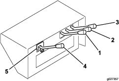
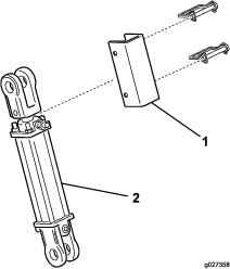
    1. Loosen the bolts and nuts securing the drive shield to the impeller housing (Figure 14) and remove the shield.

      g027367

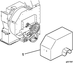
      Note: You do not need to disconnect the drive shaft to adjust the belt tension.

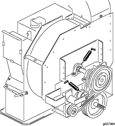
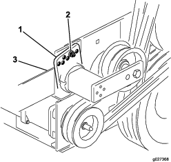
    2. On back side of the frame, loosen the bolt securing the belt tensioner to the frame (Figure 14).

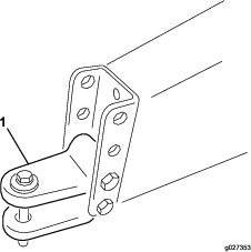
    3. Remove the bolt and nut securing the tensioner guide to the drive mount to release the belt tension (Figure 15).

      g027368
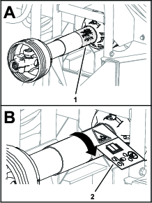
    4. Using a large wrench, rotate the tensioner clockwise until the decal is aligned with 15° on the tensioner tube.

      Important: Align the tensioner as close to 15° as possible without going under.Rotating the tensioner too far over 15° can over-tension the belt, rotating it under 15° will leave the belt too loose; both can damage the machine.

    5. Insert the bolt into the aligned guide holes and secure it with the nut.

      Important: If the holes are not exactly aligned, rotate the guide to the next higher hole until it is aligned.

    6. Tighten the bolt at the back side of the frame to lock the tensioner.

    7. Install the drive shield to the impeller housing with the bolts and nuts removed previously.

    Storage

    1. Park the machine on a level surface; engage the parking brake; shut off the engine; remove the key; and wait for all movement to stop before leaving the machine.

    2. Thoroughly clean the machine. The impeller housing should be free of dirt, leaves, and debris.

    3. Check the tire pressure; refer to Checking the Tire Air Pressure.

    4. Tighten all fasteners as necessary.

    5. Grease or oil all grease fittings and pivot points. Wipe up any excess lubricant.

    6. Place a light coat of grease on the splines of the PTO shaft.

    7. Lightly sand and use touch-up paint on painted areas that are scratched, chipped, or rusted. Repair any dents in the metal body.