Introduction

This machine is intended to be used by professional, hired operators in commercial applications. It is designed primarily for metering and dispersing materials, under a range of moisture conditions, without clogging or drastically affecting the dispersion.

Important: Read this information carefully to learn how to operate and maintain your product properly and to avoid injury and product damage. You are responsible for operating the product properly and safely.

Whenever you need service, genuine Toro parts, or additional information, contact an Authorized Service Dealer or Toro Customer Service and have the model and serial numbers of your product ready. Figure 1 identifies the location of the model and serial numbers on the product. Write the numbers in the space provided.

Important: With your mobile device, you can scan the QR code (if equipped) on the serial number plate to access warranty, parts, and other product information.

g237535

This manual identifies potential hazards and has safety messages identified by the safety-alert symbol (Figure 2), which signals a hazard that may cause serious injury or death if you do not follow the recommended precautions.

g000502

This manual uses 2 words to highlight information. Important calls attention to special mechanical information and Note emphasizes general information worthy of special attention.

This product complies with all relevant European directives, for details please see the separate product specific Declaration of Conformity (DOC) sheet.

Electromagnetic Compatibility
Domestic: This device complies with FCC Rules Part 15. Operation is subject to the following two conditions: (1) This device may not cause harmful interference and (2) this device must accept any interference that may be received, including interference that may cause undesirable operation.
This equipment generates and uses radio frequency energy and if not installed and used properly, in strict accordance with the manufacturer's instructions, may cause interference to radio and television reception. It has been type tested and found to comply within the limits of a FCC Class B computing device in accordance with the specifications in Subpart J of Part 15 of FCC Rules, as stated above. However, there is no guarantee that interference will not occur in a particular installation. If this equipment does cause interference to radio or television reception, which can be determined by turning the equipment off and on, the user is encouraged to try to correct the interference by one or more of the following measures:Reorient the receiving antenna, relocate the remote control receiver with respect to the radio/TV antenna or plug the controller into a different outlet so that the controller and radio/TV are on different branch circuits.If necessary, the user should consult the dealer or an experienced radio/television technician for additional suggestions.The user may find the following booklet prepared by the Federal Communications Commission helpful: "How to Identify and Resolve Radio-TV Interference Problems". This booklet is available from the U.S. Government Printing Office, Washington, DC 20402. Stock No. 004-000-00345-4.
FCC ID: W7OMRF24J40MDME-Base, OA3MRF24J40MA-Hand Held
IC: 7693A-24J40MDME-Base, 7693A-24J40MA-Hand Held
Operation is subject to the following two conditions: (1) this device may not cause interference, and (2) this device must accept any interference, including interference that may cause undesired operation of the device.
Japan Electromagnetic Compatibility Certification
Handheld:Graphic
RF2CAN:Graphic
Mexico Electromagnetic Compatibility Certification
Handheld:Graphic
RF2CAN:Graphic
Korea Electromagnetic Compatibility Certification(Decal provided in separate kit)
Handheld:Graphic
RF2CAN:Graphic
Singapore Electromagnetic Compatibility Certification
Handheld:TWM240008_IDA_N4023-15
RF2CAN:TWM-240005_IDA_N4024-15
Morocco Electromagnetic Compatibility Certification
AGREE PAR L’ANRT MAROC
  
NUMERO d’agrement: MR 14078 ANRT 2017
Delivre d'agrement::29/05/2017

The DOT tire information is located on the side of each tire. This information gives load and speed ratings. Replacement tires should have the same or better ratings. Refer to Specifications to ensure that the tires meet or exceed the weight requirements of your machine.

Warning

CALIFORNIA

Proposition 65 Warning

Use of this product may cause exposure to chemicals known to the State of California to cause cancer, birth defects, or other reproductive harm.

Safety

General Safety

This product is capable of causing personal injury. Always follow all safety instructions to avoid serious personal injury.

Using this product for purposes other than its intended use could prove dangerous to you and bystanders.

  • Read and understand the contents of both this Operator’s Manual and the operator’s manual of the tow vehicle before using this machine. Ensure that everyone using this product knows how to use this machine and the tow vehicle and understands the warnings.

  • Do not put your hands or feet near moving components of the machine.

  • Do not operate the machine without all guards and other safety protective devices in place and working on the machine.

  • Keep the machine away from bystanders while it is moving.

  • Keep children out of the operating area. Never allow children to operate the machine.

  • Stop the machine, engage the parking brake, shut off the engine, remove the key, and wait for all moving parts to stop before servicing, fueling, or unclogging the machine.

Improperly using or maintaining this machine can result in injury. To reduce the potential for injury, comply with these safety instructions and always pay attention to the safety-alert symbol Graphic, which means Caution, Warning, or Danger—personal safety instruction. Failure to comply with these instructions may result in personal injury or death.

Safety and Instructional Decals

Graphic

Safety decals and instructions are easily visible to the operator and are located near any area of potential danger. Replace any decal that is damaged or missing.

decal115-2047
decal119-0217
decal119-6804
decal119-6805
decal119-6806
decal119-6808
decal119-6809
decal119-6810
decal119-6814
decal119-6815
decal119-6817
decal119-6819
decal119-6820
decal119-6853
decal119-6854
decal119-6855
decal119-6856
decal131-6766
decal133-8061
decal144-3536

Setup

Note: Determine the left and right sides of the machine from the normal operating position.

Setting Up the Machine Base Model

  1. Remove the base model machine from the shipping crate.

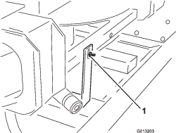
  2. At the rear of the twin spinner, remove the bolt and nut attaching the machine lifting device shipping bracket to the twin spinner (Figure 3).

    g013203
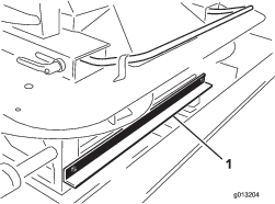
  3. At the front of the twin spinner, remove the 2 bolts and nuts attaching the machine lifting device shipping bracket to the twin spinner (Figure 4).

    g013204
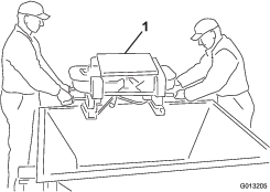
  4. Lift the twin spinner out of the hopper using the twin spinner outer grab handles and place the twin spinner unit on the ground (Figure 5).

    Caution

    The twin spinner weighs 68 kg (150 lb) and could cause personal injury if you do not lift it appropriately.

    For safety, use 2 people to lift the twin spinner.

    g013205
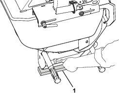
  5. Remove the 4 screws from the legs of the twin spinner. With the help of a partner, lift the twin spinner and remove the packing studs and packing foam (Figure 6).

    g391101
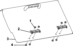
  6. Loosely install the hinge to the hopper door using the supplied carriage bolts (1/4 x 5/8 inch) and locknuts (Figure 7). Line up the hinge on the door with the hinge on the machine and then tighten the fasteners.

    Note:

    g391690
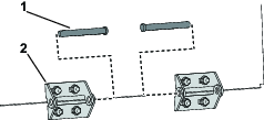
  7. Install the hopper door to the machine by connecting the 2 sides of the hinge with the hinge pin as shown in Figure 8 and Figure 9.

    g432224
    g432225
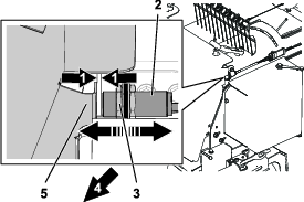
  8. Adjust the clearance between the sensor and the hopper door to 3 mm (1/8 inch) as shown in Figure 10 using the adjustment nuts. The gap should be no wider than 6 mm (1/4 inch).

    Note: The sensor must not touch the hopper door.

    Note: If the hopper door does not align with the sensor, remove the carriage bolts and locknuts in step 7 and adjust the horizontal position of the hopper door. After the door is in the correct position, secure it using the removed locknuts and carriage bolts.

    g432232
  9. Torque the adjustment nuts in step 11 to 20 N•m (15 ft-lb).

Installing the Power Harness

Parts needed for this procedure:

Power harness1
Socket bracket1
Socket bracket, heavy1
Carriage screw2
Flange nut2
Screw2
Flange nut2

The tow vehicle power harness provides the electrical power required by the control systems of the machine. Install this harness on the vehicle you plan to use to operate the machine. If you use more than 1 vehicle with the machine, purchase an additional power harnesses from your authorized Toro distributor.

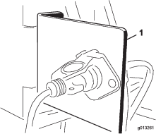
  1. Mount the socket bracket to a fixed point at the rear of the tow vehicle using 1 of the mounting brackets provided (Figure 11).

    Note: If the tow vehicle is equipped with a dump box, ensure that the socket bracket clears all parts of the tow vehicle.

    Important: Ensure that none of the wiring is loose or in the way of any mechanical components.

    g013261
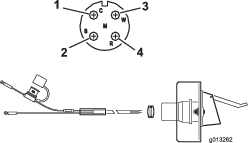
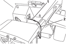
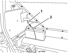
  2. Route and secure the electrical wiring from the battery to the electrical plug bracket (Figure 12).

    g013262
  3. Feed the wiring through the socket bracket and install the black rubber grommet over the wiring (Figure 12).

  4. Bolt the socket to the socket bracket using the bolts (1/4 inch).

  5. Connect the red wire (power) to the positive post on the battery, then connect the black wire (ground) to the negative post on the battery.

Installing the Hopper Extension Kit

Parts needed for this procedure:

Hopper extension (front)1
Hopper extension (rear)1
Bolt9
Flange nut9
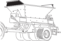
  1. Remove the hopper extensions from the box and identify the front and the rear (Figure 13 and Figure 14).

    g013263
    g013264
  2. Using the hardware provided, attach the hopper extensions to the hopper. Place the nuts on the outside of the hopper.

    g237533

Mounting the Hopper to the Tow Chassis

Tow Chassis Configuration Only

Parts needed for this procedure:

Bolt (5/16 x 1 inch)6
Flange nut (5/16 inch)6

Warning

Lifting the bed and hopper of the machine while assembled to a Tow-Behind Chassis, ProGator, Workman, or TDC Chassis may damage the lifting bracket and seriously injure you or other bystanders.

Disassemble the bed from the Tow-Behind Chassis, ProGator, Workman, or TDC Chassis, and lift only the bed and hopper.

Note: If you are mounting the ProPass top dresser onto something other than the tow chassis, refer to the installation instructions for your application.

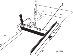
  1. Attach a lifting device to the lifting bracket bolted inside the hopper assembly (Figure 16).

    g013209
  2. Using a lifting mechanism, position the hopper over the tow chassis.

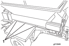
  3. Line up the 6 mounting holes (3 per side) and install the bolts (5/16 x 1 inch) and flange nuts (5/16 inch).

    g013949
  4. Remove the lifting bracket from the hopper sides and install the bolts to the hopper sides.

    Note: Retain the lifting bracket for future use; do not discard it.

Connecting the Intermediate Wire Harness

Parts needed for this procedure:

Intermediate wire harness1

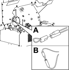
Plug the intermediate wire harness into the power harness connector on the machine (Figure 18 or Figure 19).

g237534
g013948

Connecting the On/Off Pendant

Model 44701

Parts needed for this procedure:

On/off pendant1

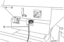
Plug the on/off pendant connector into the connector on the machine (Figure 20).

g013947

Assembling the Handheld Remote

Model 44751

Parts needed for this procedure:

Handheld remote1
AA batteries4
Magnetic bracket1
Screws, small6
  1. Remove the rubber bands securing the remote halves together, and remove the back cover.

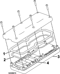
  2. Install the batteries into the terminal cradle observing proper polarity. The cradle is embossed with polarity markings for each terminal (Figure 21).

    Note: If you install the batteries incorrectly, the handheld remote will not operate.

    g028875
  3. Ensure that the steel gasket and rubber seal are seated in the channel in the handheld remote and set the back cover in place (Figure 21).

  4. Secure the cover with 6 screws (Figure 21) and torque them to 1.5 to 1.7 N∙m (13 to 15 in-lb).

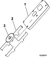
  5. Assemble the handheld remote into the magnetic remote bracket, slide the bracket halves together, and tighten the bolt in the magnet (Figure 22).

    g028874

Mounting the Wireless Remote

Model 44751

Parts needed for this procedure:

Controller mount assembly1
Wireless remote assembly1

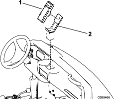
Insert the controller mount assembly into a cup holder or similar opening on the tow vehicle and use it to store wireless handheld remote. Also, the wireless remote magnet sticks to any steel surface.

g030466

Product Overview

Flow Control Valve for Floor

Model 44701

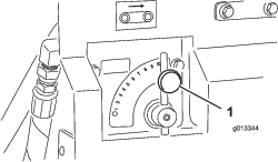
A hydraulic flow control valve controls the speed of the conveyor belt.

The highest speed setting is 10 and is typical for most applications found on the color-coded operation system decals. Use lower settings for very light applications.

g013344

Flow Control Valve for Options

Model 44701
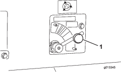
g013345

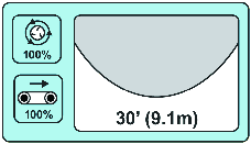
A hydraulic flow control valve controls the speed of the option (twin spinner). The spinner icon indicates the speed percentage for the wireless controller only—for standard hydraulics, place the control in the appropriate color area, starting at the dotted line and adjust speeds within the color zone as required.

On/Off Pendant

Model 44701

Use the 2 switches on the On/Off pendant to run the conveyor belt or the option (Figure 26). Keep the On/Off pendant within reach of the operator.

g013346

E-Stop Button

Model 44751

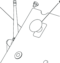
When finished working with the machine, always press the E-STOP button (Figure 27) to disable the electrical system. When beginning work with the machine you must pull the E-STOP button back out before turning on the handheld remote.

Note: When you are finished operating the machine, press the E-stop button to prevent discharging the battery of the tow vehicle.

g237530

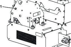
Diagnostic LED Function

After pulling up the E-STOP button, the diagnostic LED (Figure 28) illuminates and remains lit for 5 seconds, turns off for 5 seconds, and then begins flashing at 3 Hz (3 flashes a second) until you turn the handheld remote on. If the light turns on for 5 seconds and then starts blinking at 10 Hz (with or without a 5 second pause), a machine fault exists; refer to Checking Fault Codes.

Note: If handheld remote is on when you pulled up the E-STOP button, the light will not flash at 3 Hz (3 flashes per second) after turning off for 5 seconds.

g237532

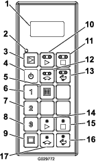
Handheld Remote

Model 44751
g029772
Weights
Base Model248 kg (546 lb)
Twin Spinner68 kg (150 lb)
Radio (Model 44751)
Frequency2.4 GHz
Max Output Power19.59 dBm

Attachments/Accessories

A selection of Toro approved attachments and accessories is available for use with the machine to enhance and expand its capabilities. Contact your Authorized Service Dealer or Distributor or go to www.Toro.com for a list of all approved attachments and accessories.

To ensure optimum performance and continued safety certification of the machine, use only genuine Toro replacement parts and accessories. Replacement parts and accessories made by other manufacturers could be dangerous, and such use could void the product warranty.

Operation

Before Operation

Before Operation Safety

  • The machine has different balance, weight, and handling characteristics compared to some other types of towed equipment. Read and understand the contents of this Operator's Manual before operating the machine. Become familiar with all controls and know how to stop quickly.

  • Never allow children or untrained people to operate or service the machine. Local regulations may restrict the age of the operator. The owner is responsible for training all operators and mechanics.

  • Become familiar with the safe operation of the equipment, operator controls, and safety signs.

  • Know how to stop the machine and shut off the engine quickly.

  • Check that operator-presence controls, safety switches, and shields are attached and functioning properly. Do not operate the machine unless they are functioning properly.

  • Keep all shields and safety devices in place. If a shield, safety device, or decal is illegible or missing, repair or replace it before operating the machine.

  • Tighten any loose nuts, bolts, and screws to ensure that the machine is in safe operating condition. Ensure that the machine components are in place and secure.

  • Ensure that your tow vehicle is suitable for use with an implement of this weight by checking with your tow vehicle supplier or manufacturer.

  • Park the machine on a level surface; engage the parking brake; shut off the engine; remove the key; and wait for all movement to stop before leaving the machine.

Daily Checks

At the start of each day, complete these safety checks before operating the machine. Report any safety problems to your supervisor. See the Safety Instructions in this manual for details.

Choosing a Tow Vehicle

Warning

Always use a suitable tow vehicle to move the machine, even for short distances. An unsuitable tow vehicle can damage the machine, or cause injury or death.

The override access is on the driver side of the hydraulic system; refer to Figure 46 in Manual Override.

A suitable tow vehicle must have a minimum towing capacity of 1405 kg (3,400 lb).

On tow-behind chassis the maximum carrying load for the machine is 907 kg (2,000 lb), with a resulting tongue weight of 113 kg (250 lb). The tare weight (no load) is 499 kg (1,100 lb), with a resulting tongue weight of 23 kg (50 lb).

The resulting tongue weight of the machine fitted with the 11 hp Hydraulic Power Pack when operating with a full load is 145 kg (320 lb). The resulting no load tongue weight is 48 kg (105 lb). The tare weight (no load) is 599 kg (1,320 lb).

On Truckster direct connect chassis the maximum carrying load for the machine is 907 kg (2,000 lb), with a resulting weight transfer of 272 kg (600 lb) to the tow vehicle. The tare weight (no load) is 544 kg (1,200 lb), with a resulting weight transfer of 52 kg (115 lb) to the tow vehicle.

Connecting the Machine to a Tow Vehicle

Warning

Standing between the machine and the tow vehicle during coupling could result in serious injury.

Do not stand between the machine and the tow vehicle during coupling.

  1. Adjust the hitch height by turning the jack stand handle(s) to keep the machine level.

  2. Connect the clevis-style hitch of the machine to the tow vehicle using an 18 mm (3/4 inch) diameter safety approved hitch pin and safety clip (not supplied). Install the hitch pin through the machine hitch and the tow-vehicle draw bar on the tow-behind chassis or through the supplied hitch mount on Truckster direct connect.

  3. Lower the hitch using the jack stand(s).

  4. When the full weight of the machine has been transferred to the tow-vehicle draw bar from the jack stand(s), pull the pin holding the jack stand(s) in place.

  5. Store the jack stand(s) as follows:

    • On tow-behind chassis turn the jack stand 90 degrees counter-clockwise until the bottom of the jack stand points to the rear of the machine. This is the traveling position.

    • On Truckster direct connect chassis move the jack stands to the rear of the machine and turn them 90 degrees until the bottom of both jack stands points to the center of the machine. This is the traveling position

  6. Attach the pressure hose and the return hose to the correct hydraulic outputs on the tow vehicle. The return hose has an inline check valve. If you reverse the hoses, some machine functions may run backwards or not work at all. Test the hydraulics before operating the machine for the first time.

    Important: Do not allow the hydraulic lines, the power cable, and the pendant cables to drag on the ground. Avoid locations where they could become pinched or cut.

  7. Plug the intermediate wire harness into the tow vehicle power connector.

  8. Check the level of the hydraulic fluid in the tank and add more to fill it, if necessary; refer to the tow vehicle’s owner’s manual.

Preparing for Operation

The machine features a unique color-coded operation system that takes the guesswork out of setting up your machine. Simply choose the spread, identify the color, and then adjust each setting to match that color to get a perfect spread every time.

Main Operation Decal

decal119-6814

Choosing the Spread

Choose the spread by reading the main operation decal found on the tailgate of the machine (Figure 30).

g013715

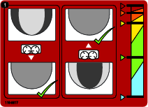
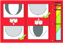
This decal shows the range of spreads available and classifies them by color (Figure 31). Each color represents a different rate of application from ultra-light to ultra-heavy. The spread density is indicated by the shaded ovals (light through heavy). The approximate width is also indicated.

Checking the Blades

Note: The machine is shipped with the spinner blades in POSITION B.

The lighter spreads (blue panel) remind you to ensure that the spinner blades are in POSITION A (Figure 32).

g013716

When the blades are in POSITION A, the inside bolts (closest to the center of the disc) are tight to the blade wall and the outside bolts (closest to the edge of the disc) are away from the blade wall.

This is critical as this position is engineered to give the optimum spread and distribution at high speeds and low sand volume.

For heavier settings (gold panel) the blades should be in POSITION B to provide the best distribution at higher volumes and slower disc speeds (Figure 33).

g013717

When the blades are in POSITION B, the inside bolts (closest to the center of the disc) are away from the blade wall and the outside bolts (closest to the edge of the disc) are tight to the blade wall.

Important: Incorrect blade position is a common reason that spread patterns fail.

Setting the Tailgate, Spinner Speed, Slide, and Floor Speed

Once you have selected the desired spread and ensured that the blades are properly adjusted, set the rest of the machine adjustments.

Each setting is indicated on the machine by corresponding color decals (Figure 34).

g013718

If you want a light dusting, the blue area indicates that your tailgate, floor speed, spinner speed, and base slide adjustment should all be in their blue positions (Figure 34).

LIGHT
Approximate Width: 9.1 m (30 ft)
Blade Position: A
Floor Speed: 100%
Spinner Speed: Blue/100%
Tailgate: Blue
Slide Adjustment: Blue

To fill aerification holes, adjust all settings to RED.

ULTRA HEAVY
Approximate Width: 2.7 m (9 ft)
Blade Position: B
Floor Speed: 100%
Spinner Speed: Red/15%
Tailgate: Red
Slide Adjustment: Red

Adjusting the Tailgate

The tailgate controls the volume of material that flows from the ProPass (Figure 35).

g013699

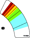
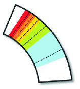
The 5 inch tailgate is divided into colors with a target starting line in each color section (Figure 36). You can increase or decrease the amount of material with the tailgate as long as you stay within the corresponding color section.

g013705

Note: The colors on the decal shown in Figure 36 correspond to the colors in the main operation decal (Figure 30).

Adjusting the Spinner Speed

Note: The colors on the decals shown in Figure 38 and Figure 39 correspond to the colors in the main operation decal (Figure 30).

g013706

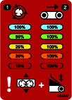
Standard Hydraulics (Model 44701): Set the hydraulic control to the dotted start line in the corresponding color area (Figure 38). You can vary the speeds if required within the corresponding color section.

g013707

Wireless Control (Model 44751): Set according to the percentage indicated in the colored section of the decal and on the chart on the back of the wireless controller (Figure 39).

decal119-6819

Adjusting the Slide

The slide adjustment positions the sand as it falls onto the discs. The decal not only indicates the color coded start position for each application, it illustrates the adjustment required to fine tune your spread; refer to Fine Tuning the Adjustments.

g013709
g013710

Note: The colors on the decal shown in Figure 41 correspond to the colors in the main operation decal (Figure 30).

Adjusting the Floor Speed

The floor speed for every setting is usually 100%; this was developed and tested in order to have 1 less factor to adjust in the Color-Coded Operating System. Typically, you should use the tailgate to reduce material volume, not the floor speed; however, if the minimum tailgate height is insufficient to reduce material flow, then decrease the floor speed.

g013711

Fine Tuning the Adjustments

The color-coded operation system was developed to take the guess work out of getting a perfect spread. However, with so many variables such as sand weight, granule size, moisture content, etc, your spread may still be uneven.

To correct this, the base setting adjustment has an illustration indicating the correct re-positioning of the base (Figure 43).

g013710

When the spread pattern is heavy on the inside of the spread simply slide the base in—toward the hopper. If your spread is heavy on the outside, slide the base out—away from the hopper.

Note: The colors on the decal shown in Figure 43 correspond to the colors in the main operation decal (Figure 30).

During Operation

During Operation Safety

  • The owner/operator can prevent and is responsible for accidents that may cause personal injury or property damage.

  • Wear appropriate clothing, including eye protection; long pants; substantial, slip-resistant footwear; and hearing protection. Tie back long hair, secure loose clothing, and do not wear loose jewelry.

  • Use your full attention while operating the machine. Do not engage in any activity that causes distractions; otherwise, injury or property damage may occur.

  • Do not operate the machine when tired, ill, or under the influence of alcohol or drugs.

  • Never carry passengers on the machine and keep bystanders and pets away from the machine during operation.

  • Keep your hands and feet out of the hopper.

  • Remain seated whenever the tow vehicle is in motion.

  • Using the machine demands attention. Failing to operate tow vehicle safely may result in an accident, tip-over of the tow vehicle, and serious injury or death. Drive carefully, and to prevent tipping or loss of control, do the following:

    • Use extreme caution, reduce the speed, and maintain distance from sand traps, ditches, water hazards, ramps, unfamiliar areas, or other hazards.

    • Reduce the speed of a loaded machine when negotiating terrain undulations to avoid causing the machine to become unstable.

    • Watch for holes or other hidden hazards.

    • Use caution when operating on a steep slope. Travel straight up and down slopes. Reduce speed when making sharp turns. Avoid turning on hillsides whenever possible.

    • Use extra caution when operating on wet surfaces, at higher speeds or with a full load. Stopping time increases with a full load. Shift into a lower gear before starting up or down a hill.

    • Avoid sudden stops and starts. Do not go from reverse to forward or forward to reverse without coming to a complete stop.

    • Do not attempt sharp turns or abrupt maneuvers or other unsafe driving actions that may cause a loss of control.

    • Be aware of your surroundings when turning or backing up the machine. Ensure that the area is clear and keep all bystanders away. Proceed slowly.

    • Always watch out for and avoid low overhangs such as tree limbs, door jambs, overhead walkways, etc. Ensure that there is enough room over head to easily clear the tow vehicle and your head.

    • Do not operate the machine when there is the risk of lightning.

    • If you are ever unsure about safe operation, stop working and ask your supervisor.

    • Do not leave the machine unattended while it is running.

  • Ensure that the machine is connected to the tow vehicle before loading or unloading.

  • Do not carry loads that exceed the load limits of the machine or the tow vehicle.

  • The stability of loads can vary—for example, high loads have a higher center of gravity. Reduce the maximum load limits to ensure better stability, if necessary.

  • To avoid causing the machine to tip over, do the following:

    • Carefully monitor the height and weight of the load. Higher and heavier loads can increase the risk of tipping.

    • Distribute the load evenly, from front to back and side to side.

    • Be careful when turning and avoid unsafe maneuvers.

    • Always ensure that the machine is connected to the tow vehicle before loading.

    • Do not put large or heavy objects into the hopper. This could damage the belt and rollers. Also ensure that the load has a uniform texture. The machine can unpredictably throw small rocks in the sand.

  • Do not stand behind the machine when unloading or spreading. The twin spinner, cross conveyor, and processor can eject particles and dust at a high speed.

  • Unload the machine or disconnect it from the tow vehicle while on a level surface.

  • Do not travel with the machine in the fully raised position. This increases the risk of tipping over the machine.

  • Do not travel with the machine in the caution range (yellow/black). When there are no attachments on the machine, travel with the machine in the lowered position.

  • Shut off the attachment when approaching people, vehicles, vehicle crossings, or pedestrian crossings.

  • Use extreme caution when traveling on hills, especially when turning.

    • Traveling across steep hills with the machine fully loaded could result in a tip-over, or a loss of traction for the machine or tow vehicle.

    • Reduce the weight of the load when traveling on steep hills and avoid piling the load high.

Slope Safety

  • Review the tow vehicle specifications to ensure that you do not exceed its slope capabilities.

  • Slopes are a major factor related to loss of control and rollover accidents, which can result in severe injury or death. The operator is responsible for safe slope operation. Operating the machine on any slope requires extra caution.

  • The operator must evaluate the site conditions to determine if the slope is safe for machine operation including surveying the site. Always use common sense and good judgment when performing this survey.

  • The operator must review the slope instructions listed below for operating the machine on slopes. Consider the operating conditions on that day to determine whether to use the machine at the site. Changes in the terrain can result in a change in slope operation for the machine.

  • Avoid starting, stopping, or turning the machine on slopes. Avoid making sudden changes in speed or direction. Make turns slowly and gradually.

  • Do not operate a machine under any conditions where traction, steering, or stability is in question.

  • Remove or mark obstructions such as ditches, holes, ruts, bumps, rocks, or other hidden hazards. Tall grass can hide obstructions. Uneven terrain could overturn the machine.

  • Be aware that operating the machine on wet grass, across slopes, or downhill may cause the machine to lose traction. Loss of traction to the drive wheels may result in sliding and a loss of braking and steering.

  • Use extreme caution when operating the machine near drop offs, ditches, embankments, water hazards, or other hazards. The machine could suddenly roll over if a wheel goes over the edge or the edge caves in. Establish a safety area between the machine and any hazard.

Operating Characteristics

The machine has balance, weight, and handling characteristics that may be different from other types of pulled equipment. Read this Operator’s Manual carefully.

With an option mounted, be aware of the ground clearance when traveling on hills. For a machine mounted on a tow-behind chassis, the ground clearance is 33 cm (13 inches) unloaded. For a machine mounted on a Truckster direct connect chassis, the ground clearance is 43 cm (17 inches) unloaded.

Controlling Machine Power

Turning the Machine Power Off or On

Model 44701

When finished working with the machine, use the pendant to stop the machine. When beginning work with the machine, start the vehicle or power pack to pressurize the hydraulic system and use the pendant to start the machine.

Turning the Machine Power Off or On

Model 44571

When finished working with the machine, always press the E-STOP button (Figure 44) to disable the electrical system. When beginning work with the machine, you must pull the E-STOP button back out before turning on the handheld remote.

g237530

Important: When done operating the machine, press the E-STOP button to prevent the tow vehicle battery from being discharged.

Operating the Machine

  1. Fill the machine hopper with the material to be spread.

  2. Ensure that the twin spinner option is installed.

  3. Adjust the gate height to the preferred setting.

  4. Adjust both flow control valves to the preferred setting. Set the belt and option speeds to the preferred setting (typically, the belt speed should be: Wireless—100%, Standard Hydraulics—#10).

  5. Park the tow vehicle 3 m (10 ft) in front of the area required for top dressing.

  6. Ensure that the on/off pendant switches are both off. On wireless models, ensure that the handheld remote functions are stopped.

  7. Ensure that the rear access door is completely closed and securely latched; refer to Raising and Lowering the Rear Access Door.

  8. Engage the hydraulics (either on the tow vehicle or on the auxiliary hydraulic power pack).

  9. Increase rpm of the tow vehicle. Turn the option on, using the on/off pendant or the handheld remote on wireless models.

  10. Drive forward to the area that requires top dressing, raising the rpm of the tow vehicle to the optimal operating range.

  11. When the machine option is directly over the beginning of the top-dressing area, use the on/off pendant or the control pendant on wireless models to turn on the conveyer belt.

    Note: For wireless models use the ALL START function instead of the OPTION START and FLOOR START functions as a single operation start feature. The option starts followed by the belt.

  12. Travel in a straight line and spread the material at a constant speed until the spread reaches the edge of the top-dressing area.

  13. Turn off the conveyor belt, turn the machine around, and position it for the next pass.

  14. Before making the next pass, check the spread pattern on the ground. Adjust the machine settings if necessary.

  15. Continue steps 11 to 14 until the entire area requiring top dressing has been completed, or the hopper is empty

  16. Turn off the conveyor belt and the option, lower the tow vehicle rpm, and disengage the hydraulics.

    Important: Always shut the conveyor off first.

Wireless Controller Safety

Model 44751

The wireless controller activates rapidly rotating parts and pinch hazards. Ensure that the ProPass is in your line of sight when operating, adjusting, or programming the wireless controller.

To ensure that the activation of the spinners and the floor is intentional, you must press the start buttons twice: once to select and once to engage. This helps prevent accidental start when making manual adjustments on the machine

If you press no buttons for 10 seconds when programing or preparing to operate the wireless controller, it enters the idle mode and returns to the last saved program or setting.

Caution

Hydraulic fluid escaping under pressure can penetrate skin and cause injury.

Power off your wireless controller and work vehicle (to ensure no hydraulic flow) before making any physical adjustments to the blades or floor.

Operating the Hydraulic Controls and Options

Model 44751

Remote-Control System

The remote-control system consists of a handheld remote, a +12 to +14.4 VDC Base Unit, and a wire harness.

Handheld Remote

g029772

Button Functions

ButtonNameFunction
GraphicON/OFFPowers the handheld remote on or off.
GraphicALL STARTProvides functional control on both the floor and option including on/off and displaying the speed.
GraphicFLOOR STARTProvides functional control of the hopper conveyor floor belt including on/off and displaying the floor speed.
GraphicFLOOR STOPStops the floor.
GraphicFLOOR DECDecreases the floor speed.
GraphicFLOOR INCIncreases the floor speed.
GraphicPRESET 1Preset values that you can store for both floor and option speeds.
GraphicPRESET 2
GraphicPRESET 3
GraphicSTOREUsed in conjunction with the PRESET button to store or establish a preset memory.
GraphicOPTION STARTProvides functional control of the rear option including on/off and displaying the option speed.
GraphicOPTION STOPStops the option.
GraphicOPTION DECDecreases the option speed.
GraphicOPTION INCIncreases the option speed.
GraphicALL STOPStops both floor and option.

Turning On the Handheld Remote

Press the ON/OFF button on the remote and wait for the it to find the base. Ensure that there are no buttons being pressed on the handheld remote while it is performing the startup routine.

Understanding the Remote Status LED

Model 44751

The remote status LED blinks slowly at 2 Hz (twice per second) when the handheld remote is transmitting but no buttons are being pressed, when the floor and option buttons active. When you press a button, the light blinks at 10 Hz.

Key Functionality Elements

  • When you turn the handheld remote on, the display should read FLR OFF and OPT OFF in approximately 5 seconds. If the words “waiting for base” are in the display, check to ensure that there is electrical power to the base unit and that the E-STOP button on the base unit is pulled out.

  • There is always a current working memory. Current working memory is not a preset. When you turn the handheld remote on, it uses the last saved work settings from current working memory.

  • Operational sequence of the handheld remote start buttons:

    1. Press the start button once (ALL START, FLOOR START, or OPTION START) calls up the current working memory setting stored in the handheld remote.

    2. Press the same start button a second time to turn on the component if the hydraulics are engaged (it shows numbers ramping up in the display).

    3. Press the same start button a third time to store the new setting established in the working memory of the remote.

  • After pressing a start button once to view the current working memory setting in a non-working mode, you have approximately 10 seconds to begin adjusting the setting or the element before the remote reverts to off. In a working mode, the 10-second rule does not apply.

  • To program a preset, you must have the elements activated or engaged first.

  • To operate from a preset, the you see the element speed percentages in the display to activate or engage them. If you see the word OFF in the display, you must recall the preset.

Manual Override

If the handheld remote is missing, damaged, or fails, you can still operate the machine to complete tasks or continue a spreading job.

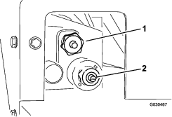
The override access is on the driver side of the hydraulic system (Figure 46).

g030467
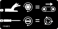
  • To adjust the floor speed (Figure 47), turn the knob clockwise. Use the maximum-floor speed of the color-coded operation system when you have no hydraulic flow. This setting is helpful when the hopper is full of sand.

    decal119-6815
  • To adjust the spinner speed (Figure 47), use a flat-head screwdriver to increase spinner speed by turning the screw clockwise or decrease spinner speed by turning the screw counterclockwise.

Note: If you are adjusting the machine with the hydraulic flow active and do not want sand being spread as you adjust, ensure that the floor is turned off.

Once your settings are acceptable, use the hydraulic flow control on your tow vehicle to turn the system on and off during operation.

Using the Handheld Remote

Model 44751

Liquid Crystal Display (LCD)

The 2-line, 8 character-per-line LCD (liquid crystal display) shows status and activity as you press the buttons of the handheld remote. It features user adjustable backlighting and contrast. The changes are saved in the current working memory of the remote. After the unit is powered down, the display uses the last settings for contrast and backlighting when you turn on the unit.

Adjusting the Backlighting

Hold the ALL STOP and the FLOOR DECREASE buttons simultaneously while observing the display until the backlighting is as desired.

Graphic + Graphic

Note: There are 3 settings: OFF, LOW, and HIGH. Backlighting consumes the most energy of all handheld remote functions. Increasing the backlighting increases power consumption and shortens the life span of the batteries; the lower the backlighting, the longer the battery life span.

Increasing the Contrast

Hold the ALL STOP and the OPTION INCREASE buttons simultaneously while observing the display until the contrast is as desired.

Graphic + Graphic

Note: There are 3 settings: OFF, LOW, and HIGH.

Decreasing the Contrast

Hold the ALL STOP and the OPTION DECREASE buttons simultaneously while observing the display until the contrast is as desired.

Graphic + Graphic

Note: There are 3 settings: OFF, LOW, and HIGH.

Checking the Battery Life, Operating Frequency, Base and Remote ID Display

Hold down the ALL STOP and OPTION STOP buttons simultaneously to display multiple points of information.

Graphic + Graphic

As you hold the buttons down, the display cycles approximately every 2 seconds displaying first the battery life expectancy in percent remaining or current battery voltage, the operating frequency (channel) on which the units communicate, then the handheld remote ID number, and finally the associated BASE Unit ID.

Caring for the Handheld Remote

Though the handheld remote is rugged, do not to drop it on hard surfaces. Wipe the handheld remote clean using a soft cloth moistened with water or a mild cleaning solution. Avoid scratching the LCD screen.

Replacing the Batteries in the Handheld Remote

The handheld remote is powered by 4 batteries (size AA alkaline, 1.5 V each) and operates between 2.4 to 3.2 V. Battery life is approximately 300 hours (continuous operation with the backlight off), but battery life longevity is affected by usage factors, particularly backlight intensity setting—the higher the backlight setting, the more power consumed resulting in shorter battery life.

Important: When using the handheld remote, always keep fresh spare batteries at hand.

  1. Loosen the bolt in the magnet on the magnetic remote bracket (Figure 48).

    g028874
  2. Slide the bracket sides apart and remove the remote (Figure 48).

  3. Remove the 6 screws from the back of the remote and remove the cover (Figure 49).

    Note: If possible, leave the rubber seal and steel gasket in the channel when removing the cover and batteries.

    g028875
  4. Remove the discharged batteries and properly dispose in accordance with local regulations.

  5. Install the batteries into the terminal cradle observing proper polarity. The cradle is embossed with polarity markings for each terminal (Figure 49).

    Note: If you install the batteries incorrectly, the handheld remote will not operate.

  6. If you accidentally removed the rubber seal and the steel gasket, replace them carefully into the channel in the handheld remote (Figure 49).

  7. Replace the cover and secure it with the 6 screws removed previously (Figure 49) and torque them to 1.5 to 1.7 N∙m (13 to 15 in-lb).

  8. Install the handheld remote into the magnetic remote bracket, slide the halves together to secure the handheld remote, and tighten the bolt in the magnet (Figure 48).

Associating the Handheld Remote with the Base

The factory initially associates the handheld remote to the base allowing them to communicate; however, there may be instances in the field when you must associate a remote and a base unit again.

  1. Press the E-Stop button to remove power from the base unit and ensure that the handheld is off.

  2. Stand near the base unit in clear line of sight.

  3. Simultaneously press and continue to hold the ON/OFF and the ALL STOP buttons.

    Graphic + Graphic

    The handheld remote goes through its initialization screens and settles on ASSOC PENDING.

  4. Continue to hold both buttons and then quickly release them when ASSOC ACTIVE is displayed (approximately 4 seconds).

    The display shows PRESS STORE.

  5. Press and hold the STORE button.

    Graphic

    The remote displays POW UP BASE.

  6. While continuing to hold the STORE button, pull out on the E-STOP button to power up the base unit.

    The handheld remote associates (links) with the base unit. Upon success, the display shows ASSOC PASS.

  7. Release the STORE button.

Important: If the display shows ASSOC EXIT, the association failed.

Note: View the handheld remote and base unit link by holding down the ALL STOP and OPTION STOP buttons at the same time. The display cycles and indicates the selected channel and the ID of the Base Unit.

Graphic + Graphic

Operating the Floor and Option Using the Handheld Remote

Model 44751

Use the following procedures to set and operate the machine floor and option (such as the twin spinner or other attachment) as follows:

  • Setting and operating the floor alone

  • Setting and operating the option alone

  • Setting and operating both floor and option together

Setting and Operating the Floor Alone

Upon initially pressing the FLOOR START button Graphic (when the floor is not running), the remote display shows the stored setting and an S is displayed after FLR (i.e. FLRS), indicating that the handheld remote is in a set-only mode. In this set-only mode, you can adjust the setting up or down, but the floor does not activate, remaining off. This allows you to set a desired floor speed or use the stored setting without causing unwanted movement. After setting the speed, press the FLOOR START button to activate the floor at the chosen setting (if you engage the hydraulics, the floor starts). Press FLOOR START a third time to store the current value in memory.

Note: Changes to the floor settings while the floor is running are immediately effective, but they are temporary unless you store the new setting by pressing FLOOR START again after changing the setting. For instance, you make an adjustment while the display shows FLRS, press Floor Start starting the floor at the adjusted setting, and then turn the handheld remote off without pressing FLOOR START again, storing the change. The next time you use the remote, the setting reverts to the previously stored value.

Note: A 10-second timer starts when you press FLOOR START and FLRS (set-only mode) displays. If you do not press a button during the 10-second interval, the display reverts to FLR and the previous state/value displays and is enforced. The timer resets to 10 seconds if you press any button while the handheld remote is in the set-only.

  1. Press the FLOOR START button.

    Graphic

    The preview value and FLRS displays.

  2. Adjust the speed setting using the INCREASE FLOOR SPEED button or the DECREASE FLOOR SPEED button.

    Graphic or Graphic
  3. Press the FLOOR START button to start the floor.

    Graphic
  4. Press the FLOOR START button to store the floor value.

    Graphic

    The display shows FLOOR STORE. The set value is used whenever the floor is started in the future until you change the setting again.

Setting and Operating the Option Alone

Upon initially pressing the OPTION START button Graphic (when the option is not running), the handheld remote display shows the stored setting and an S is displayed after OPT (i.e. OPTS), indicating that the remote is in a set-only mode. In this set-only mode, you can adjust the setting up or down, but the option does not activate, remaining off. This allows you to set a desired option speed or use the stored setting without causing unwanted movement. After setting the speed, press the OPTION START button to activate the option at the chosen setting (if you engage the hydraulics , the option starts). Press OPTION START a third time to store the current value in memory.

Note: Changes to the option settings while the option is running are immediately effective, but they are temporary unless you store the new setting by pressing OPTION START again after changing the setting. For instance, you make an adjustment while the display shows OPTS, press OPTION START starting the option at the adjusted setting, and then turn the handheld remote off without pressing OPTION START again, storing the change. The next time you use the remote, the setting reverts to the previously stored value.

Note: A 10-second timer starts when you press OPTION START and FLRS (set-only mode) displays. If you do not press a button during the 10-second interval, the display reverts to FLR and the previous state/value displays and is enforced. The timer resets to 10 seconds if you press any button while the handheld remote is in the set-only.

  1. Press the OPTION START button.

    Graphic

    The preview value and FLRS displays.

  2. Adjust the speed setting using the INCREASE OPTION SPEED button or the DECREASE OPTION SPEED button.

    Graphic or Graphic
  3. Press the OPTION START button to start the option.

    Graphic
  4. Press the OPTION START button to store the option value.

    Graphic

    The display shows OPTION STORE. The set value is used whenever the option is started in the future until you change the setting again.

Setting and Operating the Floor and Option Together

Upon initially pressing the ALL START button Graphic (when the option is not running), the remote display shows the floor and option stored settings and an S is displayed after FLR and OPT (in other words, FLRS and OPTS), indicating that the handheld remote is in a set-only mode. In this set-only mode, you can adjust either setting up or down, but the floor and option do not activate, remaining off. This allows you to set the desired speeds or use the stored settings without causing unwanted movement. After setting the speeds, press the ALL START button to activate the floor and option at the chosen setting (if the hydraulics are engaged, the floor and option start). Press ALL START a third time to store the current value in memory.

Note: Changes to the settings while the floor and option are running are immediately effective, but they are temporary unless you store the new setting by pressing ALL START again after changing the setting. For instance, you make an adjustment while the display shows FLRS and OPTS, press ALL START starting the floor and option at the adjusted setting, and then turn the handheld remote off without pressing ALL START again, storing the change. The next time you use the remote, the settings revert to the previously stored values.

Note: A 10-second timer starts when you press ALL START and set-only mode displays. If you do not press a button during the 10-second interval, the display reverts to FLR and OPT and the previous state/value displays and is used. The timer resets to 10 seconds if any button is pressed while the handheld remote is in the set-only.

  1. Press the ALL START button.

    Graphic

    The preview values and FLRS and OPTS display.

  2. Adjust the speed settings as follows:

    • Adjust the floor speed setting using the using the INCREASE FLOOR SPEED button or the DECREASE FLOOR SPEED button.

      Graphic or Graphic
    • Adjust the option speed setting using the using the INCREASE OPTION SPEED button or the DECREASE OPTION SPEED button.

      Graphic or Graphic
  3. Press the ALL START button to run the floor and option.

    Graphic
  4. Press the ALL START button to store the values.

    Graphic

    The display shows ALL STORE. The set value is used whenever the option is started in the future until you change the setting again.

    Note: You must run both the floor and option to store the settings using the ALL START button. If neither or only 1 is running, pressing the ALL START button either starts them both or starts the 1 that was not running. Nothing is stored, and the previously stored floor and the option settings display.It is important to realize that the stored command for the floor and option are used twice, once in the event of an individual command using the FLOOR START or OPTION START buttons, and once in the event of a combined action using ALL START; in either case, it is the same number.

Handheld Remote Preset Modes

Model 44751

Setting the Preset 1, 2, and 3 Buttons

The handheld remote has 3 PRESET buttons which you can program with floor and option speed settings. Each PRESET button acts like a preview mode for the ALL START button, except that they use different, user defined quick reference speed values.

If the floor and/or the option happen to be running at the time you press a PRESET button, a preview value of both floor and option settings is displayed; if you then press the ALL START button, the current operating values are replaced by the preset values. If you do not press the ALL-START button within 10 seconds, the system reverts to the previously stored values.

Use the following procedure to set the values of a PRESET button:

  1. Start both the floor and option either individually or by using the ALL START button.

    Graphic
  2. Set the desired speeds of both floor and option by using the appropriate INCREASE and DECREASE speed buttons for each output.

  3. Press and hold the STORE button and then press the desired PRESET button (1, 2, or 3).

    Graphic then Graphic, Graphic, or Graphic

    The screen displays PRESET SAVED.

Note: If you hold the STORE button and press a PRESET button while either the floor or option are off, no new value is stored for either floor or option; the preset holds the values previously stored.

Using a Preset Mode

  1. Press the desired PRESET button (1, 2 or 3) to display the floor and option settings.

  2. Press the ALL START button to start the floor and option (if the hydraulics are turned on).

  3. Use the START and STOP buttons to control the floor and option as desired.

Loading the Hopper

Warning

To avoid hazardous operation, the hopper must be used as intended:

  • Do not carry passengers in the hopper.

  • Do not carry loads that exceed the load limits of the machine, or the tow vehicle; refer to Specifications.

  • The stability of loads can vary—for example, high loads have a higher center of gravity. Reduce the maximum load limits to ensure better stability, if necessary.

  1. Connect the machine to the tow vehicle.

  2. Load the hopper with material.

    Important: Do not put large or heavy objects into the hopper. Material that is larger than the rear gate opening may damage the belt and rear gate assembly. Also ensure that the load has a uniform texture. The machine can unpredictably throw small rocks in the sand.

    To avoid causing the machine to tip over (see safety decals in this manual):

    • Carefully monitor the height and weight of the load. Higher and heavier loads can increase the risk of tipping.

    • Distribute the load evenly, front to back and side to side.

    • Be careful when turning and avoid an unsafe maneuver.

Unloading the Hopper

Warning

The machine is capable of amputating hands and feet.

Keep hands and feet away from the hopper guard on the spinner guard and the spinner assembly when the machine is operating or when the hydraulic power pack engine, on the tow vehicle, is running.

Do not stand behind the machine when unloading or spreading. The twin spinner ejects particles and dust at a high speed.

Do not unload the machine while it is on a slope.

Warning

Unloading the machine when it is not connected to the tow vehicle may cause the load to shift and the machine to tip over.

Ensure that the machine is connected to the tow vehicle before unloading.

Traveling

The machine is designed only for off-road use. The maximum recommended speed without a load is 24 km/h (15 mph).

Maintain safe control of the machine. Do not attempt sharp turns, abrupt maneuver, or other unsafe driving actions.

Slow down before turning, especially on wet, sandy, and slippery surfaces. Turning clearances are limited if you have an option mounted on the machine.

Caution

Using the machine in an unsafe manner could result in serious injury or death.

Be aware of your surroundings when turning or backing up. Ensure that the area is clear and keep all bystanders away. Proceed slowly.

Turn off the option when approaching people, vehicles, vehicle crossings, or pedestrian crossings.

Note: Heavy loads and wet or rough surfaces increase the time it takes to stop, and reduce the ability to turn quickly and safely.

After Operation

After Operation Safety

  • Park the machine on a firm, level surface. Avoid soft ground because the jack leg could sink and cause the machine to tip over.

  • Do not disconnect the machine from the tow vehicle on hills, or without engaging the front jack and rear jack leg.

  • Ensure that the rear jack leg and the hopper are in the down position. Put a spacer (such as a piece of wood) underneath the rear leg when the gap to the ground exceeds 2 inches (5 cm).

  • When disconnecting the machine, always chock the wheels to prevent movement.

  • Keep all parts of the machine in good working condition and all hardware tightened.

  • Replace all worn, damaged, or missing decals.

Disconnecting the Machine from a Tow Vehicle

  1. Park the tow vehicle and the machine on dry, level ground.

  2. Engage the parking brake on the tow vehicle, shut off the engine, and remove the key.

  3. Place blocks under 2 wheels of the machine (front and back).

  4. Relieve the pressure from the hydraulic system.

  5. Disconnect the hydraulic hoses, coil the hoses, and store them on the front of the machine.

  6. Disconnect the intermediate power cord from the tow vehicle.

  7. Lower the jack stand(s) as follows:

    • On tow-behind chassis, turn the jack stand 90 degrees (clockwise) to the down position to support the machine

    • On Truckster direct connect chassis, move the jack stands to the front of the machine and turn them 90 degrees until the bottom of both jack stands points to the ground.

  8. Lift the machine with the jack stand(s) until the weight is off the tow-vehicle draw bar.

  9. Pull out the hitch pin.

  10. Ensure that there is no further connection between the machine and the tow vehicle.

Parking the Machine

Always park the machine on a level surface. Place blocks under 2 wheels of the machine (front and back if it is in the vehicle-mounted configuration).

Warning

Disconnecting the machine from the tow vehicle on a slope could cause the machine to move unexpectedly.

Do not disconnect the machine from the tow vehicle on a slope. Ensure that the front jack is in the support position. 

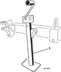
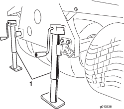
To rotate the jack stand from the vertical (support) position to a horizontal (traveling) position, pull out the jack stand support pin and swivel the jack. Ensure that the jack stand is attached to the machine and in the correct position during operation. On Toro tow-behind chassis the jack stand is located on the hitch tube (Figure 50). On Truckster direct connect chassis 2 jack stands are used (Figure 51). Use the jack storage mounts on the rear of the chassis during operation.

g013337
g013338

Using the Storage Stand

  1. Park the work vehicle in the storage spot for the machine.

    Note: The storage spot must be a hard and level surface.

  2. Disconnect the electrical connection from the work vehicle.

  3. Disconnect the machine hydraulic lines from the work vehicle.

  4. With the work vehicle in neutral gear, engage the parking brake and start the engine.

  5. Using the vehicle lift cylinder, raise the front of the machine high enough to install the front storage stand legs.

  6. Shut off the engine.

    Warning

    Working on the machine while it is on the storage stand could result in serious injury or death.

    Do not climb under or perform work on the machine while it is on the storage stand.

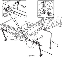
  7. Insert the front storage legs and the rear jack stands into the machine tubes and secure them with the locking pins (Figure 52).

    g013777
  8. Using the vehicle lift cylinder, lower the front of the machine until the front storage stand legs begin to touch the ground.

  9. Raise the 2 rear-storage jack stands until the pressure is off the mounting pins that secure the machine cross tube to the Workman frame.

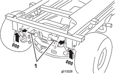
  10. Remove the rear lynch pins, hitch pins, and washers (Figure 53).

    g013228
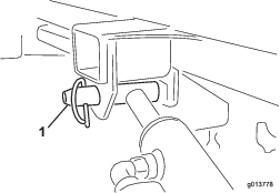
  11. With 1 hand, hold the lift cylinder. With the other hand, remove the lift cylinder’s locking pin (Figure 54).

    g013778
  12. Store the cylinders in the storage clips. Engage the hydraulic lift lock lever on the vehicle to prevent accidental extension of the lift cylinders.

  13. Raise the rear jack stands until enough clearance is attained to drive the vehicle away from the machine.

  14. Walk around the machine. Ensure that it clears the frame of the work vehicle and the machine is secure within each of the 4 storage-stand legs.

  15. Shift the transmission of the work vehicle to neutral, engage the parking brake and start the engine.

  16. Disengage the parking brake and slowly drive the work vehicle forward, away from the machine truck-mount on the storage stand.

Transporting the Machine

Important: Before loading the machine on to or off from the trailer, remove the twin spinner assembly to avoid damaging it.

  • Use care when loading or unloading the machine into a trailer or a truck.

  • Use full-width ramps for loading the machine into a trailer or a truck.

Refer to Operator’s Manual for your tow chassis and tow vehicle the tie-down locations of the machine.

Note: If that is not possible, secure the machine hood to the frame with a strap, or remove the hood and transport and secure it separately; otherwise, the hood may blow off during transport.

  1. If installed, remove the twin spinner assembly.

  2. Drive the tow vehicle up the ramp.

  3. Shut off the engine, remove the key, and engage the parking brake.

  4. Tie down the machine near the wheels with straps, chains, or cables.

    Note: Refer to local regulations for tie-down requirements.

  5. Secure blocks at the wheels of the machine to the bed of the trailer or truck.

Maintenance

Note: Download a free copy of the electrical or hydraulic schematic by visiting www.Toro.com and searching for your machine from the Manuals link on the home page.

Warning

Working on the machine before disconnecting all power sources could result in serious personal injury or death.

Disconnect all power sources to the machine before doing maintenance work.

Maintenance Safety

  • Before servicing or adjusting the machine, stop the machine, shut off the engine, engage the parking brake, remove the key, and wait for all moving parts to stop.

  • Perform only those maintenance instructions described in this manual. If major repairs are ever needed or assistance is desired, contact an authorized Toro distributor.

  • Ensure that the machine is in safe operating condition by keeping nuts, bolts, and screws tight.

  • If possible, do not perform maintenance while the engine is running. Keep away from moving parts.

  • Do not check or adjust the chain tension when the tow vehicle engine is running.

  • Carefully release pressure from components with stored energy.

  • Support the machine with blocks or storage stands when working beneath it. Never rely on the hydraulics on the tow vehicle to support the machine.

  • Check the tine mounting bolts daily to ensure that they are tightened to specification.

  • After maintaining or adjusting the machine, ensure that the hood is closed and latched and that all guards are installed.

Lubrication

Grease the Machine

Base Model
Maintenance Service IntervalMaintenance Procedure
After the first 25 hours
  • Grease the machine.
  • Every 40 hours
  • Grease the machine.Grease the machine daily when operating in extremely dusty and dirty conditions.
    • Use an all-purpose automotive grease.

    • Lubricate all bearings, bushings, and chains.

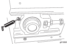
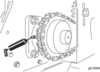
    Several grease fittings are located on the machine (Figure 55 and Figure 56).

    1. Clean the grease fittings.

    2. Pump the grease into the bearings and the bushings.

    3. Clean off the excess grease.

      g013352
      g013353

    Greasing the Tow-Behind Chassis

    Maintenance Service IntervalMaintenance Procedure
    After the first 25 hours
  • Yearly or before storage
  • Use an all-purpose automotive grease.

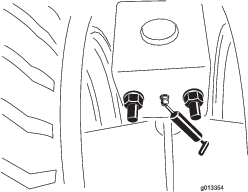
    1. Clean the grease fittings (Figure 57).

    2. Pump the grease into the bearings and the bushings.

    3. Clean off the excess grease.

    g013354

    Greasing the Wheel Bearings

    Optional Tow Chassis
    Maintenance Service IntervalMaintenance Procedure
    Every 300 hours
  • Grease the wheel bearings.
  • Clean and pack the wheel bearings.

    Checking the Tires and Wheels

    Optional Tow-Type Chassis
    Maintenance Service IntervalMaintenance Procedure
    Before each use or daily
  • Check the tires and wheels.
    • Check the tire-air pressure of the tow vehicle; refer to the Operator’s Manual for the tow vehicle.

    • Check that the tire-air pressure for the optional tow chassis is 69 kPa (10 psi), or as recommended by the tire manufacturer.

    • Check the tires for excessive damage or wear.

    • Check that the wheel bolts are tight and that none of the bolts are missing.

    Hydraulic System Safety

    • Ensure that all hydraulic-fluid hoses and lines are in good condition and all hydraulic connections and fittings are tight before applying pressure to the hydraulic system.

    • Seek immediate medical attention if fluid is injected into skin. Injected fluid must be surgically removed within a few hours by a doctor.

    • Keep your body and hands away from pinhole leaks or nozzles that eject high-pressure hydraulic fluid.

    • Use cardboard or paper to find hydraulic leaks.

    • Safely relieve all pressure in the hydraulic system before performing any work on the hydraulic system.

    Hydraulic Specification

    The machine is shipped from the factory filled with high-quality hydraulic fluid. Check the level of hydraulic fluid before the machine is first started and daily thereafter. The recommended replacement fluid is as follows:

     Toro Premium Transmission/Hydraulic Tractor Fluid (Available in 5 gallon pails or 55 gallon drums. See parts catalog or Toro distributor for part numbers.)

    Alternative fluids: If the specified fluid is not available, other universal tractor hydraulic fluids (UTHF) may be used, but they must be only conventional, petroleum-based products, not synthetics or biodegradable fluids. The specifications must fall within the listed range for all the following material properties and the fluid should meet listed industry standards. Check with your fluid supplier to see if the fluid meets these specifications.

    Note: Toro assumes no responsibility for damage caused by improper hydraulic fluid substitutions, so use only products from reputable manufacturers who stand behind their recommendation.

    Material Properties:
    Viscosity, ASTM D445cSt @ 40°C (104°F) 55 to 62
    Viscosity Index ASTM D2270140 to 152
    Pour Point, ASTM D97-37°C to -43°C (-35°F to -46°F)
    Industry Specifications: API GL-4, AGCO Powerfluid 821 XL, Ford New Holland FNHA-2-C-201.00, Kubota UDT, John Deere J20C, Vickers 35VQ25, and Volvo WB-101/BM
     

    Note: Many hydraulic fluids are almost colorless, making it difficult to spot leaks. A red dye additive for the hydraulic system oil is available in 20 ml (2/3 fl oz) bottles. 1 bottle is sufficient for 15 to 22 L (4 to 6 US gallons) of hydraulic fluid. Order Part No. 44-2500 from your authorized Toro distributor.

    Checking the Hydraulic System

    Maintenance Service IntervalMaintenance Procedure
    Before each use or daily
  • Check the hydraulic system.
    • Check the hydraulic system for fluid leaks. If you find a leak, tighten the fitting, or replace or repair the damaged part.

    • Check the hydraulic hoses for wear or visible damage.

    • For machines with the optional hydraulic power pack, check the hydraulic-fluid level of the reservoir. Fill the reservoir with fluid if necessary.

    • For machines using hydraulic power from the tow vehicle, check the hydraulic-fluid level of the tow vehicle; refer to the Operator’s Manual for the tow vehicle.

    Maintaining the Bed and Hopper

    Checking the Rear Gate

    Maintenance Service IntervalMaintenance Procedure
    Before each use or daily
  • Check the rear gate.
  • Check that the adjustable section of the rear gate opens and closes without sticking.

    Stowing and Checking the Jack Stands

    Maintenance Service IntervalMaintenance Procedure
    Before each use or daily
  • Stow and check the jack stands.
    • Stow the jack stand(s) in the up position before traveling. On the Truckster direct connect chassis, stow the jack stands at the rear of the machine.

    • Check that the hitch pin and jack stand are not damaged, and the safety pin is in place. (Replace safety pins if missing or damaged).

    • Check that the hitch connections are tight.

    Checking Other Components

    Maintenance Service IntervalMaintenance Procedure
    Before each use or daily
  • Check other components.
    • Check the blades on the twin spinner discs for wear. Replace when they wear thin.

    • Check the twin spinner housing for signs of cracking or corrosion. Replace wear plates as required.

    • Check that the safety decals are undamaged and legible; otherwise, replace them.

    Raising and Lowering the Rear Access Door

    Warning

    The machine is equipped with a safety shutoff switch at the top right corner of the rear access door; if the door is lowered the machine should not operate.

    • Do not attempt to operate the machine with the rear access door open.

    • Do not operate the machine if this switch is not functioning properly; contact your authorized Toro dealer.

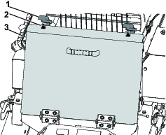
    1. Unhook the door latches from the hooks and lower the rear access door.
      g432241

      Important: Ensure that the rear access door is fully raised and securely latched before starting the machine.

    2. Raise the rear access door and hook the latch handles to the latch hooks on the top of the rear access door.

    Maintaining the Conveyor Belt System

    Checking the Belt seal and Rear Gate Seal

    Maintenance Service IntervalMaintenance Procedure
    Before each use or daily
  • Check the belt seal and rear gate seal.
    • Check all rubber seals for wear or damage. Replace or repair the seals if any leakage occurs.

    • Check and adjust the conveyor belt cleaning scraper. Ensure that the scraper is in full contact with the belt across its length.

    Checking the Conveyor Belt and Rollers

    • Check that the conveyor belt tracks straight on the rollers and does not slip—make adjustments if necessary; refer to Adjusting the Tracking of the Conveyor Belt.

    • Check the front and rear roller bearings every 2 months for wear or visible damage.

    • Check the condition and tension of the drive chain and the sprockets.

      Important: Check for trapped spreading material between conveyor bed, belt, and rollers. Refer to Washing the Machine.

    Adjusting the Conveyor Belt Tension

    Perform the tensioning procedure only if the belt is slipping, if it has been replaced, or if it has been loosened to replace other parts.

    1. Place the belt’s V-guide in the guides of the front and rear rollers.

    2. Tighten the 2 belt adjustment nuts evenly until the belt is snug.

      Note: If necessary, remove the front idler roller cover and lower the rear access door.

    3. Fully load the machine with the heaviest material you expect to use.

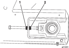
    4. With 2 wrenches, hold the end of the tensioner rod stationary and then loosen the locking nut, which is the nut closest to the end of the rod (Figure 59).
      g013351
    5. Turn the conveyor belt on and check if the belt is slipping.

    6. If so, stop the belt and tighten both adjuster nuts half a turn. Do not over-tension.

    7. Repeat steps 5 and 6 until the conveyor belt stops slipping.

    8. Tighten the locking nuts and install the yellow safety covers

    Adjusting the Tracking of the Conveyor Belt

    The conveyor belt system is self-tracking. Both the front and rear rollers have a groove in the middle for the belt’s V-guide to run in. Sometimes, the belt may track outside the grooves. To track the belt, do the following:

    1. Determine which side the belt is tracking towards.

    2. Remove the safety covers from both front corners.

    3. On the side the belt is tracking towards, hold the end of the tensioner rod stationary, then loosen the locking nut and tighten the adjuster nut by 2 flats of the nut (Figure 59).

    4. Tighten both locking nuts and turn on the conveyor belt.

    5. Check the tracking movement. Repeat the above steps until the belt tracks back to the correct position.

      Important: Be patient! Do not over-tension the belt.

    6. Install both safety covers.

    Unclogging the Conveyor Belt

    Important: Do not use your hands to remove an obstruction from the conveyor belt.

    1. Open the rear access door; refer to Raising and Lowering the Rear Access Door.

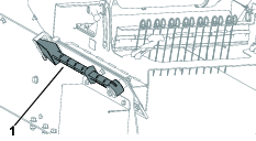
    2. Use the cleanout tool to break up and remove obstructions from the conveyor belt.
      g435545
    3. Close the rear access door; refer to Raising and Lowering the Rear Access Door.

    Washing the Machine

    Salts, road tar, tree sap, fertilizers, or chemicals may damage the painted finish of the machine. Wash off these deposits as soon as possible with detergent and water. Additional cleaners or solvents may be needed, but ensure that they are safe for painted surfaces.

    Warning

    Flammable fluids and cleaners with toxic vapors are hazardous to your health.

    Do not use flammable fluids or cleaners with toxic vapors. Follow the manufacturer’s recommendations.

    Important: Do not use a high-pressure washer. This can remove paint, safety decals, and grease, and can also damage components.

    1. Remove the option before cleaning and wash it separately.

    2. Remove the handheld remote.

    3. Wash the body of the machine with warm water and a mild detergent

    4. Completely rinse off the detergent residue with clean water before it dries.

    5. Lower the rear access door, refer to Raising and Lowering the Rear Access Door.

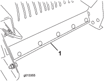
    6. Remove the belt cleaning scraper assembly from the rear of the machine (Figure 61).
      g013355
    7. Raise the front of the machine as high as necessary.

    8. If you have a truck-mounted machine, use the lift cylinder on the tow vehicle; refer to the tow vehicle’s owner’s manual.

    9. If you have a tow-behind or Truckster direct connect chassis, use the jack stand on the chassis.

    10. Fully open the rear gate and spray water inside the hopper assembly and the rear gate area. Inspect the side seals and replace if necessary.

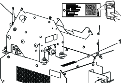
    11. Locate the clean-out decal on the front of the machine (Figure 62), using a garden hose, spray through the front guard mesh until the belly pan is completely clear of material (Figure 63).

      Note: When the covers are removed for greasing, take the opportunity to wash out any trapped spreading material.

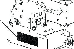
      g013714
      g237531
    12. Inspect the hopper, bottom guard, conveyor belt, bed, and rollers to ensure that all trapped material is gone.

    13. Lower the machine back into the normal operating position

    14. Install the belt cleaning scraper assembly. Push the scraper mount bar onto the belt. Ensure that the scraper is as vertical as possible, but still in contact with the belt.

    15. Raise and securely latch the rear access door, refer to Raising and Lowering the Rear Access Door.
    Storage

    Before storing the machine for the season, do the following:

    1. Park the machine on a level surface; engage the parking brake; shut off the engine; remove the key; and wait for all movement to stop before leaving the machine.
    2. Thoroughly clean the machine. Remove parts if necessary.

    3. Remove the handheld remote.

    4. Ensure that the emergency stop button is pushed.

    5. Check all fasteners and tighten, if necessary.

    6. Grease all fittings and pivot points. Wipe off any excess lubricant.

    7. Lightly sand any painted areas that are scratched, chipped, or rusted, and apply touch-up paint.

    8. Store the machine indoors, if possible.

    Troubleshooting

    Checking Fault Codes

    Model 44751

    If the Diagnostic LED indicates that there is a system fault, check the fault codes to determine what is wrong with the machine; refer to Diagnostic LED Function.

    Fault Code Table

    CodeLED Flash PatternBehaviorDetails
    Machine Specific Faults
    11Blink once, pause, blink once, long pause, then repeatLost communication with BASE.The connector is not plugged in; locate and plug in the loose or disconnected harness connector.
    Something is wrong with the wire harness; contact your Toro Distributor.
    The BASE is bad; contact your authorized Toro distributor.
    12Blink once, pause, blink twice, long pause, then repeatVersion incompatibility of the BASE and/or HHThe wrong software is installed (install the correct software from Toro DIAG); contact your authorized Toro distributor.
    13Blink once, pause, blink 3 times, long pause, then repeatWrong HH—not implemented on RevAThe wrong product associated with the handheld remote control (i.e. trying to operate ProPass unit with a MH-400 handheld)

    Entering Diagnostic Mode and Checking the Codes

    1. Push the E-STOP button down to turn off the power.

    2. Pull the tethered cap off the 2 diagnostic shunt connectors (Figure 64, A).

    3. Connect the diagnostic shunt connectors together (Figure 64, B).

      g238424
    4. Pull the E-STOP up to turn on the power.

    5. Count the number of flashes to determine the fault code, then use the fault code table to determine the source of the fault.

      Note: If there are multiple faults, both faults flash, then a long pause, then the flash sequences repeats.

    Resetting the Fault Code

    After solving the problem, reset the fault codes by disconnecting and reconnecting diagnostic connectors. The diagnostic light flashes continuously at 1 Hz (1 flash per second).

    Exiting Diagnostic Mode

    1. Push the E-STOP button down to turn off the power; refer to E-Stop Button.

    2. Disconnect the diagnostic shunt connectors (Figure 64, B).

    3. Push the tethered cap onto the 2 diagnostic shunt connectors (Figure 64, A).

    4. Pull the E-STOP up to turn on the power.

    Handheld Remote Messages

    Model 44751

    Message Table

    Displayed MessageDescription
    ASSOC PENDINGAn association yet to be made.
    ASSOC ACTIVEAn association attempt is in progress.
    POWER UP BASEPower up the Base Unit.
    ASSOC PASSThe association attempt was successful.
    ASSOC EXITExiting the association mode.
    ASSOC FAILAn association attempt failed.
    PRESS STOREPress the STORE button.
    ALL STOREAll current set values are stored in current working memory.
    OPTION STOREThe current option settings are stored in current working memory.
    BELT STOREThe current floor settings are stored in current working memory.
    PRESET 1 STOREThe current Preset 1 setting is stored in current working memory.
    PRESET 2 STOREThe current Preset 2 setting is stored in current working memory.
    PRESET 3 STOREThe current Preset 3 setting is stored in current working memory.
    WAITING FOR BASEThe handheld remote is waiting for a base unit response.
    HOPPER UPThe handheld remote is sending the hopper raise command.
    HOPPER DOWNThe handheld remote is sending hopper lower command.
    PROPASS REV XXThe product to which the system is set to control.
    MH400 REV XXThe product to which the system is set to control.
    BAT XX%Battery X.X VThe remaining battery life in percentage.The remaining battery life in voltage.
    CHANNEL XThe current channel used by the system.
    HH ID XXXXXXThe identity of the handheld remote.
    BASE ID XXXXXXIdentity of the base unit
    FLR XX% OPT XX%The current floor speed in percent.The current option speed in percent.
    FLRS XX% OPTS XX%Display of the stored regular floor speed and option speed with 0% command to the output; allows the operator to decide to use the current setting or change it.
    FLR OFFOPT OFFDisplays the status of the floor and option when they are shut off.
    SERVICE ACTIVEThe service tool is active.
    SERVICE NO APPService has no valid application to run.