Safety
Safety and Instructional Decals
 |
Safety decals and instructions are easily visible to the operator and are located near any area of potential danger. Replace any decal that is damaged or missing. |


Installation
Preparing the Machine
-
Park the machine on a level surface.
-
Engage the parking brake.
-
Shut off the engine and remove the key.
-
Disconnect the negative battery cable from the battery post.
-
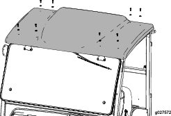
Remove the bolts securing the top of the cab (Figure 1) and carefully lift off the top of the cab.
Note: Your cab may not look exactly like the figure. You may need to remove more bolts than shown in Figure 1.
Installing the Mounts
Parts needed for this procedure:
| Left mount | 1 |
| Right mount | 1 |
| Bolt (M6) | 8 |
| Nut | 8 |
| Extension plate (GTX machines only) | 2 |
| Rear mount | 1 |
| Hex-head bolt (1/4 x 7/8 inch) | 1 |
| Speed nut | 1 |
| Tie clip | 3 |
Installing the Front Mounts
-
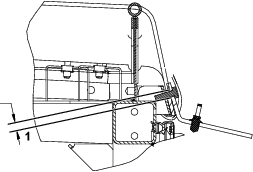
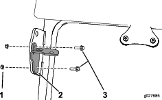
Secure the right mount to the front, right lifting point of the cab using 2 bolts (M6) and 2 nuts (Figure 2).
Note: If your cab is equipped with the Side Mirror Kit, remove the hardware that is securing the mirror brackets onto the lifting points and use the hardware included in this kit.
-
Secure the left mount to the front, left lifting point of the cab using 2 bolts (M6) and 2 nuts (Figure 2).
Installing the Front Mounts
-
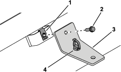
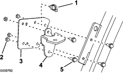
Install a tie clip to the right mount (Figure 3).
-
Install the right mount to 1 extension plate using 2 bolts and 2 nuts (Figure 3).
-
Secure the extension plate to the front, right lifting point of the cab using the 2 bolts and 2 nuts (Figure 3).
Note: If your cab is equipped with the Side Mirror Kit, remove the hardware that is securing the mirror brackets onto the lifting points and use the hardware included in this kit.
-
Repeat steps 1 through 3 to install the left mount onto the front, left lifting point.
Installing the Fuse, Switch, and Wire Harness
Parts needed for this procedure:
| Fuse (5 A) | 1 |
| Switch | 1 |
| Decal 130-5989 | 1 |
| Decal 145-7727 | 1 |
| Wire harness | 1 |
| Magnet tie wrap (GTX machines only) | 7 |
Installing the Fuse
Install the fuse into the opening in the fuse block as shown in Figure 6.

Installing the Switch
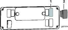
From the underside of the cab control panel, push the plug out of the hole shown in Figure 7 and install the work-light switch into this hole.
Applying the Decals
Apply decals 130-5989 and 145-7727 to the console panel assembly as shown in Figure 8.

Routing the Wire Harness
Routing the Wire Harness
-
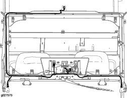
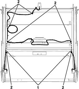
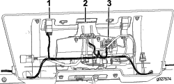
Install the wire harness as shown in Figure 11.
Note: Slit the foam at the locations shown in Figure 11 to route the harness.
-
Secure the wire harness to the machine using the tie clips in the extension plates and using 7 magnet tie wraps in the locations shown in Figure 11.
-
Connect the wire harness to the switch, fuse block, and ground terminal (Figure 12).
Installing the Work Lights
Parts needed for this procedure:
| Work-light assembly | 3 |
-
Install the top of the cab that was removed in Preparing the Machine onto the machine.
-
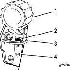
Remove the nut and bolt from each work-light assembly and secure them to the brackets as shown in Figure 13.
-
Plug the wire harness into the work-light assemblies.
Connecting the Battery
Connect the negative battery cable to the battery post.
Operation
Controls
Work-Light Switch
Press the work-light switch to the ON position to activate the work lights.
