Installation
Preparing the Machine
-
Park the machine on a level surface.
-
Ensure that the parking brake is engaged; refer to your Operator's Manual.
-
Lower the cutting unit (if equipped).
-
Shut off the machine and remove the key.
-
Turn the battery-disconnect switch to the OFF position.
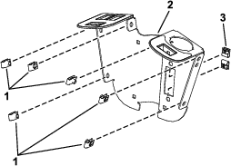
Installing the Clips and Speed Nuts
Installing the Switch Mount
Parts needed for this procedure:
| Mount bracket | 2 |
| Carriage bolt (1/4 x 2 inches) | 4 |
| Locknut (1/4 inch) | 2 |
| Hex-head screw (1/4 x 3/4 inch) | 2 |
| Flange nut (1/4 inch) | 2 |
| Flasher | 1 |
| Wire harness | 1 |
| Cable tie | 2 |
| Fuse cover | 1 |
| Thumb screw | 2 |
| Push nut | 2 |
| Screw (#10 x 3/8 inch) | 2 |
| Multi-function switch | 1 |
| Hole plug | 3 |
| Rocker switch | 1 |
| Control cover | 1 |
| Hex-head screw (1/4 x 3/4 inch) | 6 |
| Switch clip | 2 |
| Push rivet | 2 |
-
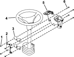
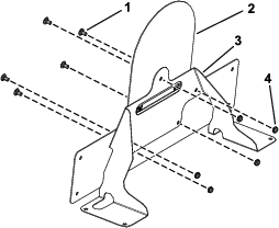
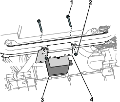
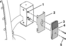
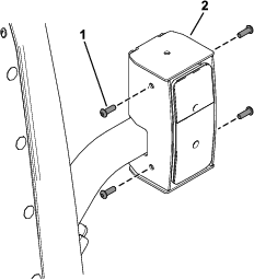
Loosely install the switch mount around the steering column using 4 carriage bolts (1/4 x 2 inches), 2 mounting brackets, fuse-mount plate, and 4 locknuts (1/4 inch) as shown in Figure 3.
-
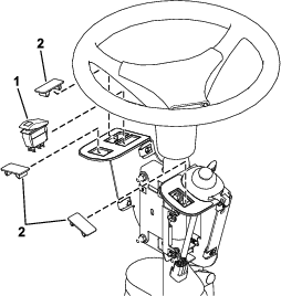
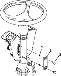
Install the multi-function switch to the switch mount and secure it using the switch clips under the hole for the switch (Figure 4).
-
Install the rocker switch and hole plugs into the switch mount (Figure 5).
-
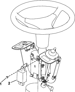
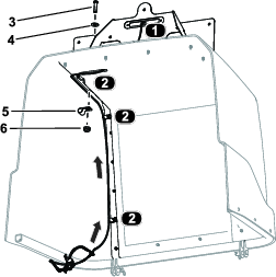
Install the flasher to the fuse-mount plate using a screw (#10 x 3/8 inch) as shown in Figure 6.
-
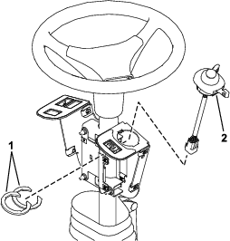
Secure the flasher using a cable tie (Figure 7).
-
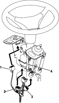
Plug the harness into the rocker switch and multi-function switch (Figure 7).
-
Plug the wire harness into the flasher (Figure 7).
-
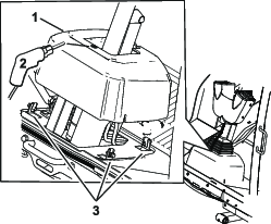
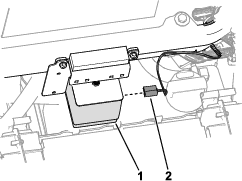
Loosen the bolts around the steering-column base (Figure 8).
-
Raise the base up and drill a 22 mm (7/8 inch) hole as shown in Figure 8.
Warning
Using a drill without proper eye protection may allow debris to enter the eye, causing injury.
When drilling, always wear eye protection.
-
Route the harness through the hole you drilled in the base.
-
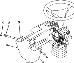
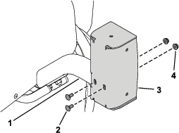
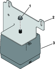
Install the fuse cover to the switch mount using 2 thumb screws and 2 push nuts (Figure 9).
Note: Ensure that the push nuts are installed on the inside of the fuse cover (Figure 9).
-
Adjust the control assembly so that the switches are accessible.
-
Tighten all the fasteners.
-
Install the control cover to the switch mount using 2 push rivets and 6 hex-head screws (1/4 x 3/4 inch) as shown in Figure 10.
Installing the Front Components
Parts needed for this procedure:
| Left light mount | 1 |
| Right light mount | 1 |
| Left light assembly | 1 |
| Right light assembly | 1 |
| Button-head bolt (1/4 x 5/8 inch) | 6 |
| Locknut (3/8 inch) | 4 |
| Light cross mount | 1 |
-
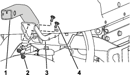
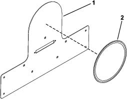
Remove the tie-down bracket from the platform (Figure 11).
Retain the parts.
-
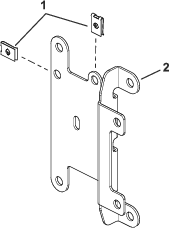
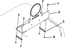
Secure the light cross mount to the platform using the previously removed bolts, nuts, and tie-down bracket (Figure 12).
-
Secure the left light mount and right light mount to the light cross mount using 3 button-head bolts (1/4 x 5/8 inch) through the speed nuts on each side (Figure 13).
-
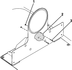
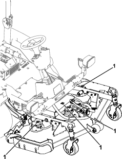
Secure the left light assembly and right light assembly to the left light mount and right light mount using the lock washer and hex nut on the light assemblies (Figure 14).
Note: Install the lights with the low beam toward the outer edge of the machine.Look at the bottom of the lights for high beam and low beam orientation.
Installing the Rear Components
Parts needed for this procedure:
| Left mount | 1 |
| Right mount | 1 |
| Left short mount | 1 |
| Right short mount | 1 |
| Right long mount | 1 |
| Carriage bolt (5/16 x 3/4 inch) | 4 |
| Flange nut (5/16 inch) | 4 |
| Carriage bolt (1/4 x 5/8 inch) | 4 |
| Locknut (1/4 inch) | 9 |
| Inner mount assembly | 2 |
| Taillight | 2 |
| Pan-head screw (#10 x 1-1/4 inches) | 4 |
| Flange nut (#10) | 4 |
| Hex-head bolt (3/8 x 3-1/4 inches) | 4 |
| Locknut (3/8 inch) | 4 |
| Marker mount | 1 |
| Speed-plate mount | 1 |
| Carriage bolt (1/4 x 1/2 inch) | 5 |
| Horn mount bracket | 1 |
| Horn | 1 |
| Speed decal | 3 |
| Left light housing | 1 |
| Right light housing | 1 |
-
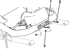
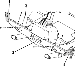
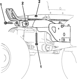
Remove the flange-head bolt (3/8 x 3 inches) and flange nut (3/8 inch) securing the bumper to the rear tube frame on each side of the bumper (Figure 15).
-
Slightly raise the battery tray and insert the left mount and right mount between the battery tray and the tube frame (Figure 16).
-
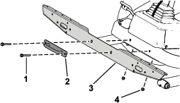
Secure the left mount and right mount to rear frame tubes using 4 hex-head bolts (3/8 x 3-1/4 inches) and 4 locknuts (3/8 inch) on each side (Figure 17).
-
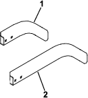
Secure the left short mount the left mount using 2 carriage bolts (5/16 x 3/4 inch) and 2 flange nuts (5/16 inch) as shown in Figure 18.
-
Perform the following step for the cutting unit that is equipped on your machine:
-
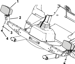
Model 31980 equipped: Secure the right long mount (Figure 19) to the right mount using 2 carriage bolts (5/16 x 3/4 inch) and 2 flange nuts (5/16 inch).
-
Model 31981 equipped: Secure the right short mount (Figure 19) to the right mount using 2 carriage bolts (5/16 x 3/4 inch) and 2 flange nuts (5/16 inch).
-
-
Secure the left light housing and right light housing to the left short mount and right short mount using 4 carriage bolts (1/4 x 5/8 inch) and 4 locknuts (1/4 inch) as shown in Figure 20.
-
Apply a speed decal to the speed-plate mount (Figure 21).
-
Secure the speed-plate mount to the marker mount using 5 carriage bolts (1/4 x 1/2 inch) and 5 locknuts (1/4 inch) as shown in Figure 22.
-
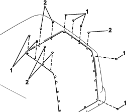
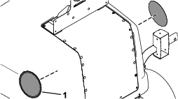
Remove the 12 plastic plugs shown in Figure 23 from the hood.
-
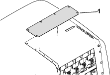
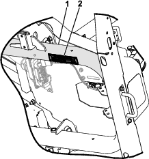
Remove the plate under the hood cover (Figure 24).
-
Install the 5 plugs to the hood cover that you retained in step 10.
-
Raise the hood; refer to the traction unit Operator’s Manual.
-
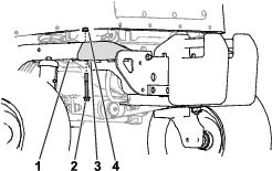
Use the existing nut on the horn to secure the horn to the horn mount bracket (Figure 25).
-
Use the existing bolts and nuts from the hood support bracket to secure the horn mount bracket to the traction-unit frame.
-
Apply the speed decals to each side of the hood (Figure 27).
Routing the Light Wire Harness
Parts needed for this procedure:
| Light wire harness | 1 |
| Flat washer | 3 |
| Hex-socket screw (1/4 x 1 inch) | 3 |
| Clamp | 3 |
| Flange nut (1/4 inch) | 3 |
| Inner mount assembly | 2 |
| Taillight | 2 |
| Pan-head screw (#10 x 1-1/4 inches) | 4 |
| Flange nut (#10) | 4 |
| Button-head bolt (1/4 x 3/4 inch) | 8 |
| Plate light | 1 |
| Screw (#6 x 1 inch) | 2 |
| Locknut (#6) | 2 |
| Back mount | 2 |
| Flange-head bolt (1/4 x 3/4 inch) | 4 |
| Locknut (1/4 inch) | 4 |
| Cable tie | 9 |
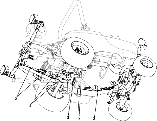
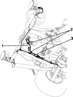
Refer to the following figures and instructions for routing the light wire harness.
-
Route the wire-harness connector labeled to the left side of the unit (Figure 28). Connect the harness to the light.
-
Route the wire-harness connector labeled to the right side of the unit (Figure 28). Connect the harness to the light.
-
Route the wire-harness connector labeled to the rear left side of the unit (Figure 28).
-
Route the wire-harness connector labeled to the rear right side of the unit (Figure 28).
-
Route the wire-harness connector labeled to the horn. Connect the harness to the horn (Figure 29).
-
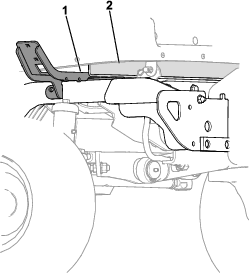
Secure the taillights to the inner mount assemblies using 4 pan-head screws (#10 x 1-1/4 inches) and 4 flange nuts (#10) as shown in Figure 30.
-
Connect the wire-harness connector labeled to the rear light (Figure 28).
-
Connect the wire-harness connector labeled to the rear light (Figure 28).
-
Secure the assembled taillights to the taillight housings using 8 button-head bolts (1/4 x 3/4 inch) as shown in Figure 31.
Ensure that you install the taillights with the yellow lens on top (Figure 30 and Figure 31).
-
Route the wire-harness connector labeled through the hood and connect it to the license light (Figure 32).
-
Secure the wire harness to the hood using 3 hex-socket screws (1/4 x 1 inch), 3 flat washers, 3 clamps, and 3 flange nuts (1/4 inch) as shown in Figure 32.
-
Secure the assembled speed-plate mount to the hood using 4 flange-head bolts (1/4 x 3/4 inch), 2 back mounts, and 4 locknuts (1/4 inch) as shown in Figure 33.
-
Secure the plate light to the assembled speed-plate mount using 2 locknuts (#6) and 2 screws (#6 x 1 inch) as shown in Figure 34.
-
Connect the wire harness to the plate light (Figure 34).
-
Install cable ties to the wire harness as shown in Figure 28.
Routing the Control Wire Harness
Parts needed for this procedure:
| Control wire harness | 1 |
| Cable tie | 2 |
Installing the Serial Plate
Parts needed for this procedure:
| Serial plate | 1 |
| Serial plate tape | 1 |
-
Stamp the serial number into the frame.
The text size must be 7 mm (1/4 inch) or larger.
-
Stamp the appropriate information into the serial plate.
-
Wipe down the bottom of the frame and serial plate with an alcohol-based wipe (Figure 36).
-
Apply the tape to the serial plate.
-
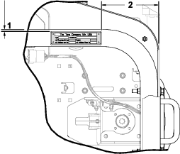
Install the plate to the frame (Figure 37).
Use the dimensions shown in Figure 38.
Installing the High-Voltage Decals
Parts needed for this procedure:
| High-voltage decal | 10 |
Apply the high-voltage decals to the following areas on traction unit and cutting unit:
-
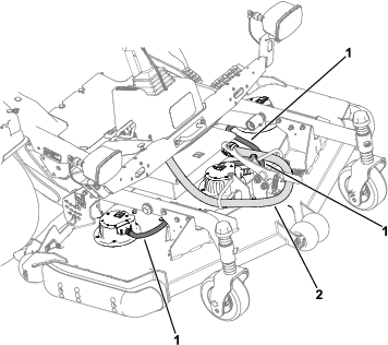
Cutting-unit motors (Figure 40)
-
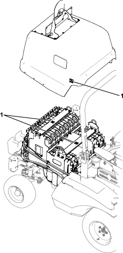
Cutting-unit controller cover (Figure 40)
-
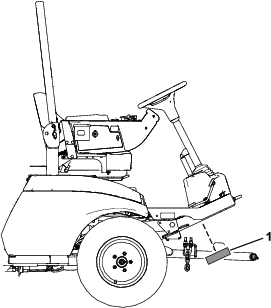
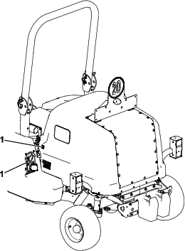
Charger port/power-disconnect switch (Figure 41)
-
Channel supports in the battery compartment (Figure 39)
Installing the Tube Wraps
Parts needed for this procedure:
| Tube wrap (147 cm or 58 inches) | 1 |
| Tube wrap (51 cm or 20 inches) | 3 |
-
Install a tube wrap (147 cm or 58 inches) to the cutting-unit connector cable.
-
Install tube wraps (51 cm or 20 inches) to the 3 cutting-unit motor cables.
Completing the Installation
Turn the battery-disconnect switch to the ON position.