Installation
Preparing the Machine
-
Park the machine on a level surface.
-
Ensure that the parking brake is engaged; refer to your Operator's Manual.
-
Lower the cutting unit (if equipped).
-
Shut off the machine and remove the key.
-
Turn the battery-disconnect switch to the OFF position.
Installing the Clips and Speed Nuts
Installing the Switch Mount
Parts needed for this procedure:
| Mount bracket | 2 |
| Carriage bolt (1/4 x 2 inches) | 4 |
| Locknut (1/4 inch) | 2 |
| Hex-head screw (1/4 x 3/4 inch) | 2 |
| Flange nut (1/4 inch) | 2 |
| Flasher | 1 |
| Wire harness | 1 |
| Cable tie | 2 |
| Fuse cover | 1 |
| Thumb screw | 2 |
| Push nut | 2 |
| Screw (#10 x 3/8 inch) | 2 |
| Multi-function switch | 1 |
| Hole plug | 3 |
| Rocker switch | 1 |
| Control cover | 1 |
| Hex-head screw (1/4 x 3/4 inch) | 6 |
| Switch clip | 2 |
| Push rivet | 2 |
-
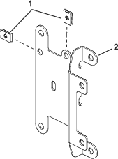
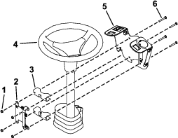
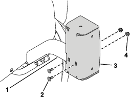
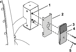
Loosely install the switch mount around the steering column using 4 carriage bolts (1/4 x 2 inches), 2 mounting brackets, fuse-mount plate, and 4 locknuts (1/4 inch) as shown in Figure 3.
-
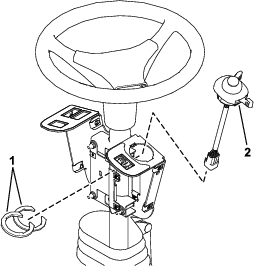
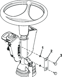
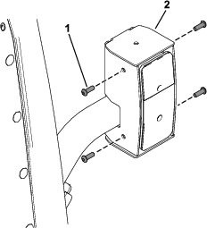
Install the multi-function switch to the switch mount and secure it using the switch clips under the hole for the switch (Figure 4).
-
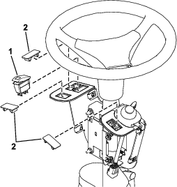
Install the rocker switch and hole plugs into the switch mount (Figure 5).
-
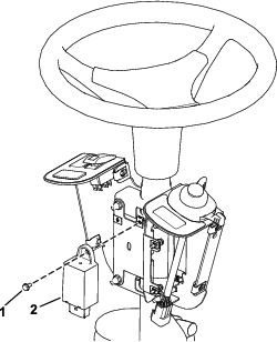
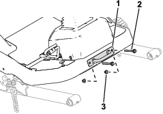
Install the flasher to the fuse-mount plate using a screw (#10 x 3/8 inch) as shown in Figure 6.
-
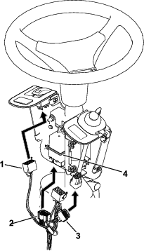
Secure the flasher using a cable tie (Figure 7).
-
Plug the harness into the rocker switch and multi-function switch (Figure 7).
-
Plug the wire harness into the flasher (Figure 7).
-
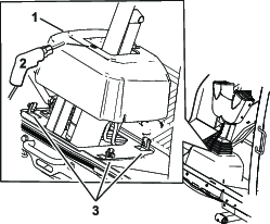
Loosen the bolts around the steering-column base (Figure 8).
-
Raise the base up and drill a 22 mm (7/8 inch) hole as shown in Figure 8.
Warning
Using a drill without proper eye protection may allow debris to enter the eye, causing injury.
When drilling, always wear eye protection.
-
Route the harness through the hole you drilled in the base.
-
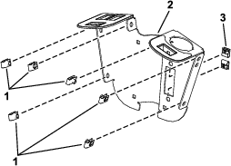
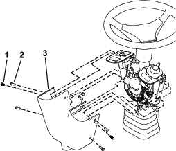
Install the fuse cover to the switch mount using 2 thumb screws and 2 push nuts (Figure 9).
Note: Ensure that the push nuts are installed on the inside of the fuse cover (Figure 9).
-
Adjust the control assembly so that the switches are accessible.
-
Tighten all the fasteners.
-
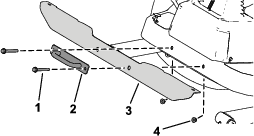
Install the control cover to the switch mount using 2 push rivets and 6 hex-head screws (1/4 x 3/4 inch) as shown in Figure 10.
Installing the Front Components
Parts needed for this procedure:
| Left light assembly | 1 |
| Right light assembly | 1 |
| Light cross mount | 1 |
| Yellow reflective tape | 2 |
-
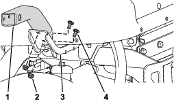
Remove the tie-down bracket from the platform (Figure 11).
Retain the parts.
-
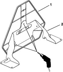
Secure the light cross mount to the platform using the previously removed bolts, nuts, and tie-down bracket (Figure 12).
-
Secure the left light assembly and right light assembly to the light cross mount using the lock washer and hex nut on the light assemblies (Figure 13).
Note: Install the lights with the low beam toward the outer edge of the machine.Look at the bottom of the lights for high beam and low beam orientation.
-
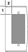
Apply the yellow reflective tape to the light cross mount using the dimensions shown in Figure 14.

Installing the Rear Components
Parts needed for this procedure:
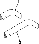
| Left mount | 1 |
| Right mount | 1 |
| Left short mount | 1 |
| Right short mount | 1 |
| Right long mount | 1 |
| Carriage bolt (5/16 x 3/4 inch) | 4 |
| Flange nut (5/16 inch) | 4 |
| Carriage bolt (1/4 x 5/8 inch) | 4 |
| Locknut (1/4 inch) | 11 |
| Hex-head bolt (3/8 x 3-1/4 inches) | 4 |
| Locknut (3/8 inch) | 4 |
| Red reflective tape | 4 |
| Marker mount | 1 |
| Back mount | 2 |
| Slow-moving vehicle sign | 1 |
| Flat washer | 3 |
| Flange-head bolt (1/4 x 3/4 inch) | 7 |
| Left light housing | 1 |
| Right light housing | 1 |
-
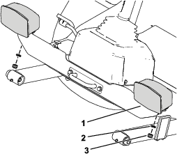
Remove the flange-head bolt (3/8 x 3 inches) and flange nut (3/8 inch) securing the bumper to the rear tube frame on each side of the bumper (Figure 15).
-
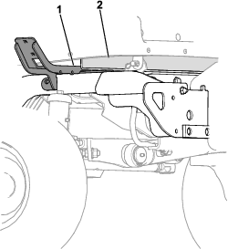
Slightly raise the battery tray and insert the left mount and right mount between the battery tray and the tube frame (Figure 16).
-
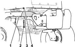
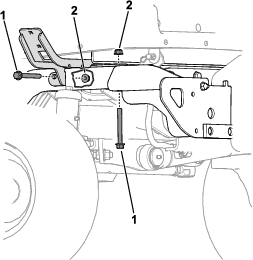
Secure the left mount and right mount to the rear frame tubes using 2 hex-head bolts (3/8 x 3-1/4 inches) and 2 locknuts (3/8 inch) on each side (Figure 17).
-
Secure the left short mount the left mount using 2 carriage bolts (5/16 x 3/4 inch) and 2 flange nuts (5/16 inch) as shown in Figure 18.
-
Perform the following step for the cutting unit that is equipped on your machine:
-
Model 31980 equipped: Secure the right long mount (Figure 19) to the right mount using 2 carriage bolts (5/16 x 3/4 inch) and 2 flange nuts (5/16 inch).
-
Model 31981 equipped: Secure the right short mount (Figure 19) to the right mount using 2 carriage bolts (5/16 x 3/4 inch) and 2 flange nuts (5/16 inch).
-
-
Secure the left light housing and right light housing to the left short mount and right short mount using 4 carriage bolts (1/4 x 5/8 inch) and 4 locknuts (1/4 inch) as shown in Figure 20.
-
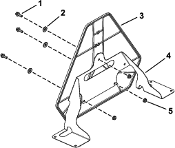
Using the marker mount as the template, drill 3 holes (5/16 inch) into the slow-moving vehicle sign (Figure 21).
-
Secure the slow-moving vehicle sign to the marker mount using 3 flange-head bolts (1/4 x 3/4 inch), 3 flat washers, and 3 locknuts (1/4 inch) as shown in Figure 22.
-
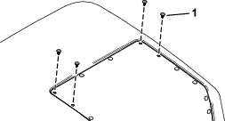
Remove the 4 plastic plugs shown in Figure 23 from the hood.
-
Raise the hood; refer to the traction unit Operator’s Manual.
-
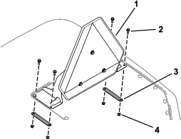
Secure the assembled slow-moving vehicle sign to the hood using 4 flange-head bolts (1/4 x 3/4 inch), 2 back mounts, and 4 locknuts (1/4 inch) as shown in Figure 24.
-
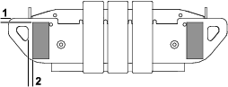
Apply 2 red reflective tape to the rear bumper and 1 reflective tape to each light housing using the dimensions shown in Figure 25 and Figure 26.
Routing the Light Wire Harness
Parts needed for this procedure:
| Light wire harness | 1 |
| Inner mount assembly | 2 |
| Taillight | 2 |
| Pan-head screw (#10 x 1-1/4 inches) | 4 |
| Flange nut (#10) | 4 |
| Button-head bolt (1/4 x 3/4 inch) | 8 |
| Cable tie | 12 |
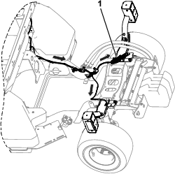
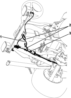
Refer to the following figures and instructions for routing the light wire harness.
-
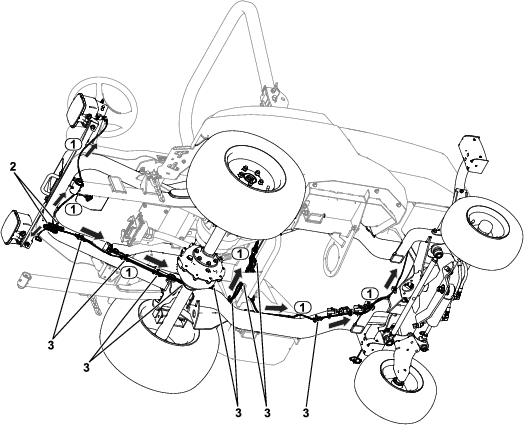
Route the wire-harness connector labeled to the left side of the unit (Figure 27). Connect the harness to the light.
-
Route the wire-harness connector labeled to the right side of the unit (Figure 27). Connect the harness to the light.
-
Route the wire-harness connector labeled to the rear left side of the unit (Figure 27).
-
Route the wire-harness connector labeled to the rear right side of the unit (Figure 27).
-
Use 2 cable ties to coil the remaining amount of wire harness under the front of the operator platform (Figure 27).
-
Secure the taillights to the inner mount assemblies using 4 pan-head screws (#10 x 1-1/4 inches) and 4 flange nuts (#10) as shown in Figure 28.
-
Connect the wire-harness connector labeled to rear light (Figure 27).
-
Connect the wire-harness connector labeled to rear light (Figure 27).
-
Secure the assembled taillights to the taillight housings using 8 button-head bolts (1/4 x 3/4 inch) as shown in Figure 29.
Ensure that you install the taillights with the yellow lens on top (Figure 28 and Figure 29).
-
Use a cable tie to coil the remaining connector together (Figure 30).
-
Install cable ties to the wire harness as shown in Figure 27.
Routing the Control Wire Harness
Parts needed for this procedure:
| Control wire harness | 1 |
| Cable tie | 2 |
Completing the Installation
Turn the battery-disconnect switch to the ON position.