Introduction

Read this information carefully to learn how to operate and maintain your product properly and to avoid injury and product damage. You are responsible for operating the product properly and safely.

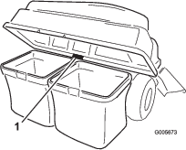
Whenever you need service, genuine parts, or additional information, contact an Authorized Service Dealer or Customer Service and have the model and serial numbers of your product ready. Figure 1 identifies the location of the model and serial numbers on the product. Write the numbers in the space provided.

g005673

This manual uses 2 words to highlight information. Important calls attention to special mechanical information and Note emphasizes general information worthy of special attention.

The safety-alert symbol (Figure 2) appears both in this manual and on the machine to identify important safety messages that you must follow to avoid accidents. This symbol will appear with the word Danger, Warning, or Caution.

  • Danger indicates an imminently hazardous situation which, if not avoided, will result in death or serious injury.

  • Warning indicates a potentially hazardous situation which, if not avoided, could result in death or serious injury.

  • Caution indicates a potentially hazardous situation which, if not avoided, may result in minor or moderate injury.

sa-black

Warning

CALIFORNIA

Proposition 65 Warning

Use of this product may cause exposure to chemicals known to the State of California to cause cancer, birth defects, or other reproductive harm.

Safety

Danger

Engines can become hot when they are operating. Severe burns can occur from contacting hot surfaces.

Allow engines, especially the muffler, to cool before touching.

Danger

Debris, such as leaves, grass, or brush can catch fire. A fire in the engine area can cause personal injury and property damage.

  • Keep the engine and muffler area free of debris accumulation.

  • Take care when opening the bagger cover to keep debris from falling onto the engine and muffler area.

  • Allow the machine to cool before storing it.

The following list contains safety information you must know.

  • Become familiar with the safe operation of the equipment, with the operator controls, and safety signs.

  • Use extra care with grass catchers or other attachments. These can change the operating characteristics and the stability of the machine.

  • Follow the manufacturer's recommendations for adding or removing wheel weights or counterweights to improve stability.

  • Do not use a grass catcher on steep slopes. A heavy grass catcher could cause loss of control or overturn the machine.

  • Slow down and use extra care on hillsides. Be sure to travel in the recommended direction on hillsides. Turf conditions can affect the stability of the machine. Use extreme caution while operating near drop-offs.

  • Keep all movement on slopes slow and gradual. Do not make sudden changes in speed, directions or turning.

  • The grass catcher can obstruct the view to the rear. Use extra care when operating in reverse.

  • Use care when loading or unloading the machine into a trailer or truck.

  • Never operate with the discharge deflector raised, removed or altered, unless using a grass catcher.

  • Keep hands and feet away from moving parts. Do not make adjustments with the engine running.

  • Stop on level ground, disengage drives, chock or block wheels, shut off engine before leaving the operator's position for any reason including emptying the grass catcher or unclogging the chute.

  • If you remove the grass catcher, be sure to install any discharge deflector or guard that might have been removed to install the grass catcher. Do not operate the mower without either the entire grass catcher or the grass deflector in place.

  • Shut off the engine before removing the grass catcher or unclogging the chute.

  • Do not leave grass in grass catcher for extended periods of time.

  • Grass catcher components are subject to wear, damage and deterioration, which could expose moving parts or allow objects to be thrown. Frequently check components and replace with manufacturer's recommended parts, when necessary.

Towing Safety

  • Do not attach towed equipment except at the hitch point.

  • Follow the attachment manufacturer's recommendation for weight limits for towed equipment and towing on slopes.

  • Never allow children or others in or on towed equipment.

  • On slopes, the weight of the towed equipment may cause loss of traction and loss of control. Reduce towed weight and slow down.

  • Stopping distance increases with the weight of the towed load. Travel slowly and allow extra distance to stop.

  • Make wide turns to keep the attachment clear of the machine.

  • Do not tow a load that weighs more than the towing machine.

Safety and Instructional Decals

Graphic

Safety decals and instructions are easily visible to the operator and are located near any area of potential danger. Replace any decal that is damaged or missing.

decal109-6809
decal131-4036
decal133-8061
decal110-6691

Setup

Preparing the Machine

  1. Park the machine on a level surface.

  2. Engage the parking brake.

  3. Shut off the engine and remove the key.

Installing the Weight

Parts needed for this procedure:

Bolt (3/8 x 1-1/4 inches)4
Locknut (3/8 inch)4
Weight mounting bracket, left1
Weight mounting bracket, right1
Washers4
Weight bracket1
Bolt (3/8 x 1 inch)2
Flat weight1
Suitcase weight1
Keyed cross bar1

Note: This procedure is only for models with control levers. Steering wheel models do not need weights installed.

Caution

The bagger changes the weight distribution of the machine. Operating the machine without the front weights may cause an unstable condition which could result in a loss of control.

Ensure the front weights are properly installed before operating the machine with the bagger attachment.

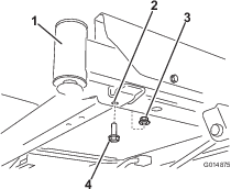
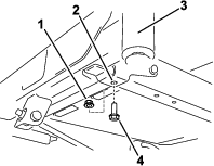
  1. Locate the front bolts on the underside of the frame (Figure 3 and Figure 4).

  2. Remove the 2 bolts (3/8 x 1 inch) and 2 locknuts (3/8 inch). Retain the locknuts.

    g014875
    g354525
  3. Locate the left and right weight-mounting brackets in loose parts.

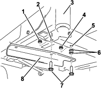
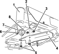
  4. Install the left bracket to the under side of the frame using 2 bolts (3/8 x 1-1/4 inches), 2 washers and 2 locknuts (3/8 inch) (Figure 5).

    Note: Use 1 locknut from the loose parts and the other from 1 of the locknuts that you previously removed.

    g354523
  5. On the right side of the machine, install the right weight-mounting bracket as follows:

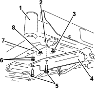
    • For machines without a foot assist lift pedal, secure the bracket using 2 bolts (3/8 x 1-1/4 inches), 2 washers and 2 locknuts (3/8 inch) (Figure 6).

      Note: Use 1 locknut from the loose parts and the other from 1 of the locknuts that you previously removed.

      g354522

      Note: For machines with a foot assist lift pedal, the washers are not used.

    • For machines with a foot assist lift pedal, Remove the forward fasteners in the foot assist lift pedal bracket and secure the bracket using 2 bolts and 2 locknuts (Figure 7).

      Note: Use 1 locknut from the loose parts and the other from 1 of the locknuts that you previously removed.

      g354524
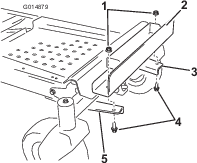
  6. Install the weight bracket to the mounting brackets by aligning the outboard holes in the bracket with the mounting brackets installed previously (Figure 8).

    Note: Make sure the bracket is centered on the frame.

  7. Secure the weight bracket with 2 bolts (3/8 x 1 inch) and 2 locknuts (3/8 inch) (Figure 8).

    g014879
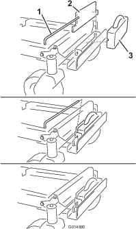
  8. Install a flat weight to the weight bracket and move it rearward, flush with the bracket (Figure 9).

    g014880
  9. Install a suitcase weight in front of the flat weight (Figure 9).

  10. Secure the weights to the weight bracket with a keyed-cross bar (Figure 9). Install the bar and rotate it 90 degrees downward to lock it in place.

  11. After you install all the weights and brackets, check that all the fasteners are tight. Tighten them as necessary.

Important: Whenever you remove the bagger attachment, remember to remove the front weights to return the proper stability to the machine.

Installing the Attachment Mount

Parts needed for this procedure:

Stabilizer bracket (For 2015 and newer Models)1
Carriage bolt (5/16 x 3/4 inch)2
Locknut (5/16 inch)4
Self-tapping screw (5/16 x 3/4 inch)2
Bolt (5/16 x 1 inch)2
Pivot frame 1
Hairpin cotter 2
Rod 2
Washer 2
Draw-bar decal1

For 2015 through 2019 Models Only

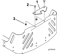
Note: The stabilizer bracket is used only on 2015 and newer models (Figure 10).

  1. Install the stabilizer bracket to the engine guard using 2 carriage bolts (5/16 x 3/4 inch) and 2 locknuts (5/16 inch) (Figure 10).

    g030494
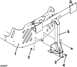
  2. Install the pivot frame to the machine frame as shown in Figure 11. Secure the pivot frame to the machine frame using 2 bolts (5/16 x 1 inch) and 2 locknuts (5/16 inch).

    g028227
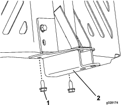
  3. Secure the pivot frame to the bottom of the machine frame using 2 self-tapping screws (5/16 x 3/4 inch) as shown in Figure 12.

    g028174
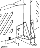
  4. Attach the draw bar decal 1.3 cm (1/2 inch) to the left of the attachment mount (Figure 13).

    g028305
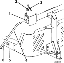
  5. Install the bent, flared end of a rod into the keyed slot in the left side of the machine frame, and move the rod rearward to seat it in the frame (Figure 14).

    Note: Repeat this step for the right side of the machine.

    g028306
  6. Insert the bent ends of the rods into the attachment mount as shown in Figure 14 and secure the end of each rod with a washer and hairpin cotter.

For 2011 through 2014 Models Only

Note: The stabilizer bracket is not used on 2011 through 2014 models.

Note: For 2011 through 2014 models, the rear-engine guard is optional for this bagger.

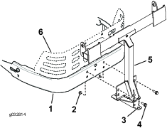
  1. Install the pivot frame to the machine frame as shown in Figure 15. Secure the pivot frame to the machine frame using 2 bolts (5/16 x 1 inch) and 2 locknuts (5/16 inch).

    g032814
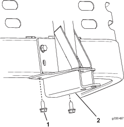
  2. Secure the pivot frame to the bottom of the machine frame using 2 self-tapping screws (5/16 x 3/4 inch) as shown in Figure 16.

    g030497
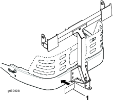
  3. Attach the draw-bar decal 1.3 cm (1/2 inch) to the left of the attachment mount (Figure 17).

    g030498
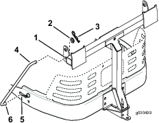
  4. Install a bent, flared end of a rod into the keyed slot in the left side of the machine frame, and move the rod rearward to seat it in the frame (Figure 18).

    Note: Repeat this step for the right side of the machine.

    g030499
  5. Insert the bent ends of the rod into the attachment mount as shown in Figure 18 and secure the end of each rod with a washer and hairpin cotter.

Installing the Latch Rod

Parts needed for this procedure:

Latch rod1
Hairpin cotter1

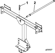
Install the latch rod with a hairpin cotter (Figure 19).

g033027

Assembling the Bagger Top

Parts needed for this procedure:

Bagger top1
Bagger screen1
  1. Turn the bagger top over.

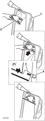
  2. Install the screen as shown in Figure 20 and that it slopes down toward the collection bags.

    Note: Make sure that the screens snap into place and the tabs engage the bagger top.

    g005666

Installing the Bagger Top

Parts needed for this procedure:

Bag frame2
Bag assembly2
Upper bagger tube1
Pivot bracket (Model 79392 only)2
Bolt (5/16 x 1 inch) (Model 79392 only)4
Nut (5/16 inch) (Model 79392 only)4
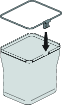
  1. Install the 2 bag frames to the 2 bag assemblies.

    g453040
  2. Install the bagger top to the bagger frame.

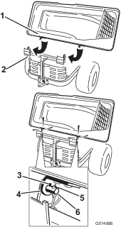
  3. For models 79390, 79391, and 79393 only: rotate the bagger top to align the key holes in the bagger top brackets with the keys in the posts on the bagger frame (Figure 22).

  4. For models 79390, 79391, and 79393 only: slide the brackets over the posts and rotate the bagger top down to the operating position.

    Note: The bagger top is easier to install if 2 people work together.

    g014888
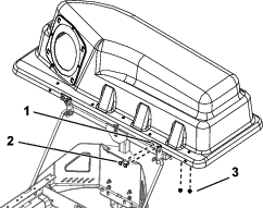
  5. For model 79392 only: install the pivot brackets onto the pivot frame (Figure 23).

  6. For model 79392 only: secure the bagger top to the pivot brackets with 4 bolts (5/16 x 1 inch) and 4 nuts (5/16 inch).

    Note: The bagger top is easier to install if 2 people work together.

    g300208
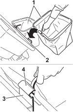
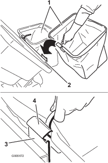
  7. Lift the bagger top and install the bags by sliding the bag frame hooks onto the retaining brackets (Figure 24).

    g033032
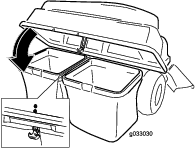
  8. Lower the bagger top onto the bags (Figure 25).

    g033030
  9. Secure the hood with the latch (Figure 25).

  10. Install the upper bagger tube by inserting the curved end into the opening in the bagger top.

    Note: Make sure that the flared end with the retention post is pointing down and forward in preparation to be mated with the Finishing Kit.

Installing the Blowout Baffle (54in Mower Deck Only)

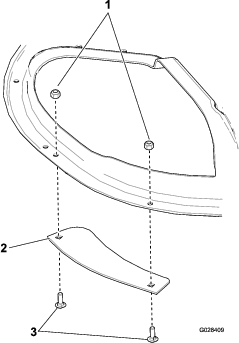
Secure the blowout baffle to the mower deck using 2 carriage bolts and 2 locknuts.

g028409

Installing the Cutoff Baffle (Models 79390, 79392, and 79393 Only)

Parts needed for this procedure:

Cutoff baffle (Model 79390 only)1
Carriage bolt (5/16 x 1-3/8 inches) (Model 79393 only)2
Flange nut (5/16 inch) (Model 79393 only)2

For Model 79390 Only

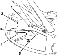
  1. Lift up the grass deflector and locate the existing cutoff baffle.

  2. Remove the locknuts and bolt securing the cutoff baffle to the underside of the mower deck. Retain all of the fasteners.

    g015220
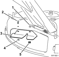
  3. Install the bagger-cutoff baffle to the underside of the deck. Secure it with the fasteners that were removed previously.

    g015221

For Model 79392 Only

Note: Certain models have the cutoff baffle installed. Proceed to the next procedure if a cutoff baffle is installed.

Important: The cutoff baffle was shipped with the machine as a loose part.

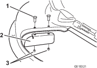
Install the cutoff baffle to the mower deck with 2 bolts (5/16 x 3/4 inch) and 2 locknuts (5/16 inch). Torque the fasteners to 7-9 N∙m (14-18 ft-lb).

g015321

For Model 79393 Only

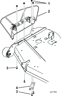
  1. Remove the plate assembly that includes the side discharge chute. Save this hardware and assembly.

  2. Remove the existing baffle under the right side of the mower deck. Save the baffle and hardware.

    g017826

    Note: When installing the existing baffle, ensure the correct holes are used for each bolt.

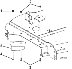
  3. Install the existing baffle with a carriage bolt (5/16 x 1 inch) and nut (5/16 inch) from the previously removed baffle.

  4. Use a new bolt (5/16 x 1-3/8 inches) and flange nut (5/16 inch) to secure the inside of the baffle.

    g017823
  5. Install a carriage bolt and flange nut into the front hole shown in Figure 31.

Installing the Chute

Parts needed for this procedure:

Chute1
Knobs (Model 79393 only)2
Flat washers (5/16 inch) (Model 79393 only)2

For Model 79390 Only

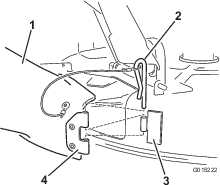
  1. Locate the chute in the loose parts. Align the holes in the hinge on the chute with the hinge on the deck.

  2. Secure the chute to the deck using the hairpin on the lanyard connected to the chute.

    g015222
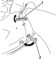
  3. Pivot the chute back and toward the deck so chute is flush with the mower deck.

    Note: As the chute mates with the deck, make sure the upper latch is out of the way of the pivot rod.

  4. On the top of the chute, engage the upper latch around the pivot rod of the deflector assembly.

    g015223
  5. Secure the chute to the mower deck by hooking the flexible latch on the chute to the retaining clasp welded on the mower deck.

For Model 79391 Only

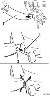
  1. Angle the metal tab at the front of the chute into the slot in the bracket welded to the mower deck.

    g015203
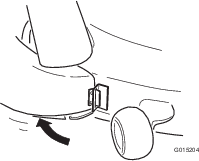
  2. Pivot the chute back and toward the deck so chute is flush with the mower deck.

    g015204

    Note: Ensure that the retaining hook on the chute is out of the way so the chute opening mounts flush to the deck.

  3. Secure the chute to the deck by hooking the flexible latch on the chute to the retaining clasp welded on the mower deck to the rear of the opening.

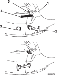
  4. Fasten the retaining hook around the pivot rod to secure the chute into position.

    g005670

For Model 79392 Only

  1. Angle the metal tab at the front of the chute into the slot in the bracket welded to the mower deck.

    g015203
  2. Pivot the chute back and toward the deck so that the chute is flush with the mower deck.

    g015204

    Note: As the chute mates with the deck, ensure that the edge of the chute is under the lip of the clip assembly installed previously.

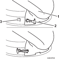
  3. On the top of the chute, engage the hook shaped latch around pivot rod of the deflector assembly.

    g005670
  4. Secure the chute to the 50 inch deck by hooking the flexible latch on the chute to the retaining clasp welded on the mower deck.

    g005756

For Model 79393 Only

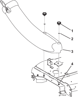
  1. Align the holes in the chute and install it onto the bolts. Secure the chute to the mower deck with the two knobs and flat washers (5/16 inch).

    g017824
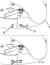
  2. Hook the flexible latch on the chute to the retaining clasp welded on the mower deck to the rear of the opening.

    g017825

Connecting with the Discharge Tube

Parts needed for this procedure:

Discharge tube1
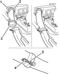
  1. Slide the curved end of the discharge tube into the opening in the bagger top.

    g010641
  2. Slide the flared end of the discharge tube over the end of the chute. Move the rubber retaining strap on the chute over the peg on the discharge tube to secure it.

  3. After the bagger installation, install the wire onto the spark plug(s).

Installing the Deck Ring (Model 79390 Only)

Parts needed for this procedure:

Deck ring4
Bolt (5/16 x 3/4 inch)8
Locknut (5/16 inch)8
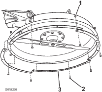
  1. Install the interlocking deck rings to the bottom of the mower deck.

    g015226
  2. Secure the rings to the deck using 8 bolts (5/16 x 3/4 inch) and 8 locknuts (5/16 inch).

Installing the Blade (Model 79390 Only)

Parts needed for this procedure:

Hi-Lift blade1
  1. Remove the existing mower blade installed on your mower deck. Refer to the Removing the Blades section in the Operator's Manual for more information.

  2. Install the Hi-Lift mower blade. Refer to the Installing the Blades section in the Operator's Manual for more information.

Operation

Note: Determine the left and right sides of the machine from the normal operating position.

Warning

To avoid personal injury, follow these procedures:

  • Become familiar with all operating and safety instructions in the Operator's Manual for the mower before using this attachment.

  • Never remove the discharge tube, bags, bagger top, or the chute while the engine is running.

  • Always shut the engine off and wait for all moving parts to stop before clearing an obstruction from the bagging system.

  • Never do maintenance or repairs while the engine is running.

Emptying the Grass Bags

Be careful when lifting or handling a grass bag that is full. To empty the grass bags:

  1. Park the machine on a level surface and disengage the blade control switch.

  2. Move the motion control levers outward to the neutral lock position, stop the engine, remove the key, set the parking brake and wait for all moving parts to stop before leaving the operating position.

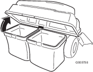
  3. Open (raise) the bagger top (Figure 45).

    g005758
  4. Compress debris into the bags. With both hands, lift up on the bag and unhook it from the retaining bracket. Empty the bag. Repeat the procedure for the other bag.

  5. Install the bags by sliding the bag frame hooks onto the retaining brackets (Figure 46).

    g005672
  6. Lower the bagger top onto the bags.

Clearing Obstructions from the Bagger

  1. Park the machine on a level surface and disengage the blade control switch.

  2. Move the motion control levers outward to the neutral lock position, stop the engine, remove the key, set the parking brake and wait for all moving parts to stop before leaving the operating position.

  3. Check the grass bags and empty them if they are full.

  4. Separate the discharge tube and chute.

  5. Remove the discharge tube and chute from the bagger top and mower deck. Using a stick or similar object, carefully remove and clear the obstruction from the mower, discharge tube, chute, and the bagger top.

  6. After you remove the obstruction, install the complete bagger system and resume operation.

Removing the Bagger

Caution

Failing to remove the front bagger weights and operating the machine without the bagger attachment may cause an unstable condition which could result in a loss of control.

  • Always remove the front weights when removing the bagger attachment.

  • If you remove the bagger attachment, remove the front weights.

The bagger can be removed by repeating the Setup sections from all installed bagger related kits in reverse order. If weights are installed, always remove the front bagger weights when removing the bagger attachments.

Note: It is only necessary to remove the cutoff baffle when installing a mulching kit.

Using the Draw Bar

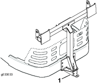
The bagger support bracket has a draw bar feature that can be used for towing.

  • Read and understand all the operating instructions of the machine.

  • When turning, slow down and observe the clearance.

  • Make wide turns and keep towed equipment clear of the towing vehicle.

  • The maximum draw bar pull is 36 kg (80 lb).

  • Excessive draw bar pull may cause hydrostatic transmission failure.

    g033033

Operating Tips

Tips for Bagging

Remembering the Size

Remember that the machine is longer and wider with this attachment installed. By turning too sharply in confined places you may damage the attachment.

Trimming

Always trim with the left side of the mower. Do not trim with the right side of the mower because you could damage the bagger chute and discharge tube.

Cutting Height

Do not set the mower cutting height too low because long grass surrounding the mower can prevent air from getting under the mower and entering the bagging system. If enough air does not get under the mower, the bagging system will plug.

Cutting Frequency

Cut the grass often, especially when it grows rapidly. You will have to cut your grass twice if it gets excessively long.

Cutting Technique

For best lawn appearance, be sure to slightly overlap the mower into the previously cut area. This helps reduce the load on the engine and reduces the chance of plugging the chute and discharge tube.

Bagging Speed

Most often you will bag with the mower throttle in the Fast position and drive at a normal ground speed. However, in extremely dry and dusty grass, you may want to slightly reduce the throttle speed and increase the ground speed of the mower. The bagging system may plug if you drive too fast and the engine speed gets too slow. On hills, it may be necessary to slow the mower ground speed. This helps maintain the engine speed and bagging efficiency. Mow downhill whenever possible.

Caution

As the bagger fills, extra weight is added to the back of the machine. If you stop and start suddenly on hills, you may lose steering control or the machine may tip.

  • Do not start or stop suddenly when going uphill or downhill. Avoid uphill starts.

  • If you do stop the machine when going uphill, disengage the blade control. Then back down the hill using a slow speed.

  • Avoid sudden turns or rapid speed changes on slopes.

  • If you remove the bagger attachment, remove the front weights.

Bagging Long Grass

Excessively long grass is heavy and may not be propelled completely into the grass bags. If this happens, the discharge tube and chute may plug. To avoid plugging the bagging system, mow the grass at a high height of cut, then lower the mower to your normal cutting height and repeat the bagging process.

Bagging Wet Grass

Always try to cut grass when it is dry because your lawn will have a neat appearance. If you must cut wet grass, use the conventional side discharge feature of the mower. Several hours later, when the clippings are dry, install the complete bagger attachment and vacuum up the grass clippings.

Signs of Plugging

As you are bagging, a small amount of grass clippings normally blow out the front of the mower. An excessive amount of clippings blowing out indicates that the bags are full or the system is plugged.

Maintenance

Note: Determine the left and right sides of the machine from the normal operating position.

Recommended Maintenance Schedule(s)

Maintenance Service IntervalMaintenance Procedure
After the first 10 hours
  • Inspect the bagger.
  • Before each use or daily
  • Clean the bagger.
  • Before storage
  • Inspect the bagger.
  • Clean the bagger.
  • Caution

    If you leave the key in the ignition switch, someone could accidently start the engine and seriously injure you or other bystanders.

    Remove the key from the ignition and disconnect the wire from the spark plug before you do any maintenance. Set the wire aside so that it does not accidentally contact the spark plug.

    Danger

    An engine can become hot while it operates. Severe burns can occur from contacting hot surfaces.

    Allow the engine, especially the muffler, to cool before touching it.

    Danger

    Debris, such as leaves, grass, or brush can catch fire. A fire in the engine area can cause personal injury and property damage.

    • Keep the engine and muffler area free of debris accumulation.

    • Take care when opening the bagger cover to keep debris from falling onto the engine and muffler area.

    • Allow the machine to cool before storing it.

    Inspecting the Bagger Attachment

    Maintenance Service IntervalMaintenance Procedure
    After the first 10 hours
  • Inspect the bagger.
  • Before storage
  • Inspect the bagger.
  • Inspect the bagger attachment after the first 10 hours of operation, and monthly thereafter.

    1. Check the chute, discharge tube, and the bagger top. Replace these parts if they are cracked or broken.

    2. Tighten all nuts, bolts, and screws.

    3. Inspect all fasteners and latches; replace any missing or damaged.

    4. Inspect the grass bags for deterioration.

      Warning

      You or bystanders could be severely injured by flying debris or thrown objects that may pass through torn, worn, or deteriorated grass bags.

      • Check the grass bags for holes, rips, wear, and other deterioration.

      • Do not wash the grass bags.

      • If the bag has deteriorated, install new grass bags supplied by the manufacturer of this bagger attachment.

    Inspecting the Mower Blades

    Inspect the mower blades regularly and whenever a blade strikes a foreign object.

    If the blades are badly worn or damaged, install new blades. Refer to your mower or mower Operator's Manual for complete blade maintenance.

    Cleaning the Bagger Attachment

    Maintenance Service IntervalMaintenance Procedure
    Before each use or daily
  • Clean the bagger.
  • Before storage
  • Clean the bagger.
  • Note: To prevent rapid deterioration of the bag material, store the bags where they will dry completely after each use.

    1. After each use, remove and wash the inside and outside of the bagger top, discharge tube, chute, and the underside of the mower, using water sprayed from a garden hose. Use a mild detergent to remove stubborn dirt.

    2. Make sure you remove matted grass from all parts.

    3. Flush the grass bags with water using garden hose to remove any debris.

    4. After washing, let all of the parts dry thoroughly.
    Storage

    Storing the Bagger Attachment

    1. Clean the bagger attachment; refer to Cleaning the Bagger Attachment.

    2. Inspect the bagger attachment for damage; refer to Inspecting the Bagger Attachment.

    3. Make sure the grass bags are empty and thoroughly dry.
    4. Store the bagger in a clean, dry place, out of direct sunlight. This protects the plastic parts and extends the life of the bagger. If you must store the bagger outside, cover it with a weatherproof cover.