


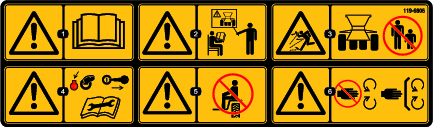
 , which means Caution, Warning,
or Danger—personal safety instruction. Failure to comply with
these instructions may result in personal injury or death.
, which means Caution, Warning,
or Danger—personal safety instruction. Failure to comply with
these instructions may result in personal injury or death.


Maintenance
Maintenance Safety
-
Before servicing or adjusting the machine, stop the machine, shut off the engine, engage the parking brake, remove the key, and wait for all moving parts to stop.
-
Perform only those maintenance instructions described in this manual. If major repairs are ever needed or assistance is desired, contact an authorized Toro distributor.
-
Before doing any maintenance work under the hopper, install the hydraulic cylinder supports.
-
Ensure that the machine is in safe operating condition by keeping nuts, bolts, and screws tight.
-
If possible, do not perform maintenance while the engine is running. Keep away from moving parts.
-
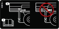
Do not check or adjust the chain tension when the tow vehicle engine is running.
-
Carefully release pressure from components with stored energy.
-
Support the machine with blocks or jack stands when working beneath it.
-
After maintaining or adjusting the machine, ensure that all guards are installed.
Recommended Maintenance Schedule(s)
| Maintenance Service Interval | Maintenance Procedure |
|---|---|
| After the first 100 hours |
|
| Before each use or daily |
|
| Every 40 hours |
|
| Every 50 hours |
|
| Monthly |
|
| Yearly |
|
Pre-Maintenance Procedures
Warning
Disconnect all power sources to the machine before doing maintenance work.
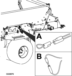
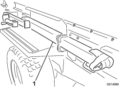
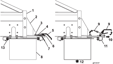
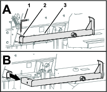
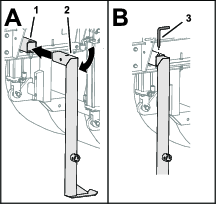
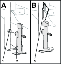
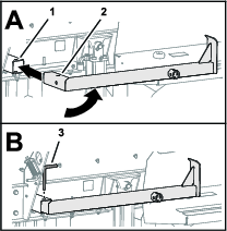
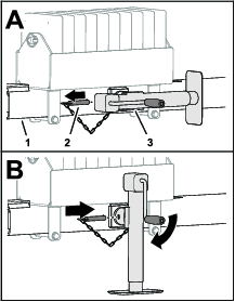
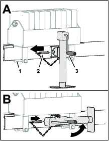
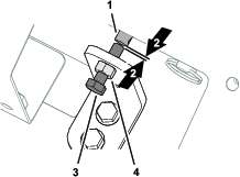
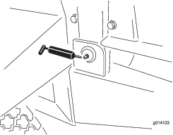
Installing the Hydraulic-Cylinder Support
Warning
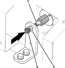
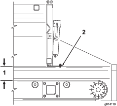
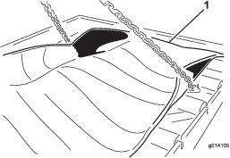
Before preforming maintenance under the hopper when it is raised, install the 2 hydraulic-cylinder supports (Figure 46).
-
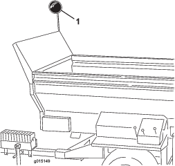
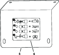
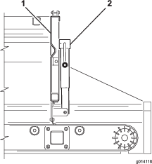
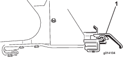
Remove the hydraulic-cylinder support located at each side of the hopper (Figure 45).
-
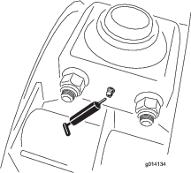
Fully tilt the hopper.
-
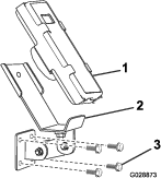
Assemble the hydraulic-cylinder supports onto the rods of the hydraulic cylinders (Figure 46).
Lubrication
Grease Specification
No. 2 lithium grease
Lubricating the Bearings and Bushings
| Maintenance Service Interval | Maintenance Procedure |
|---|---|
| Every 50 hours |
|
-
Wipe the grease fitting clean so foreign matter cannot be forced into the bearing or bushing.
-
Pump grease into the bearing or bushing.
-
Wipe up any excess grease.
The bearing and bushing lubrication points are as follows:
Drive System Maintenance
Checking the Tire and Wheels
| Maintenance Service Interval | Maintenance Procedure |
|---|---|
| Before each use or daily |
|
-
Check the tire air pressure is 172 kPa (25 psi) for 84 cm (33 inch) tires and 207 kPa (30 psi) for 81 cm (32 inch) tires, or as recommended by the tire manufacturer.
-
Check the tires for excessive wear or visible damage.
-
Check that the wheel bolts are tight, and none are missing.
Changing Tires
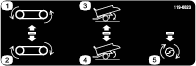
Changing an Outside Tire
-
Engage the parking brake of the traction unit.
-
Remove any optional attachments from the machine.
-
Remove all material from the hopper.
-
Chock the tires at the opposite side of the damaged tire.
-
Loosen the 6 lug nuts on the flat tire, but do not remove them.
-
Hoist or jack the machine until the tire is off the floor or ground, and support the machine with jack stands.
Ensure that the machine is stable.
-
Remove the loose lug nuts and remove the tire.
-
Repair or replace the damaged tire.
-
Install the wheel onto the machine by reversing the above steps.
Note: Ensure that the wheel is centered on the hub and all six wheel bolts are tight. Torque in a crossover pattern to 135 N∙m (100 ft-lb).
Changing an Inside Tire
Important: Keep the machine attached to the traction unit.
-
Engage the parking brake of the traction unit.
-
Remove any optional attachments from the machine.
-
Remove all material from the hopper.
-
Chock the tires at the opposite side of the damaged tire.
-
On the side with the damaged tire, remove the 4 bolts and 4 locknuts securing the walking beam suspension bearings to the chassis.
Loosen but do not remove the outside wheel nuts to provide clearance for bearing bolts.
-
Hoist or jack the machine until you can roll the inside tire and walking beam axle assembly away from the machine and support the machine with jack stands.
Ensure that the machine is stable.
-
Remove the damaged tire.
-
Repair or replace the damaged tire.
-
Install the tire onto the machine by reversing the above steps.
Note: Ensure that the wheel is centered on the hub and all six wheel bolts and the bearing bolts are tight to 135 N∙m (100 ft-lb).
Brake Maintenance
Inspecting the Electric Brakes
| Maintenance Service Interval | Maintenance Procedure |
|---|---|
| Monthly |
|
| Yearly |
|
-
Visual inspection of your brake shoes and linings.
-
Inspect and service your electric brakes.
Adjusting the Electric Brakes
| Maintenance Service Interval | Maintenance Procedure |
|---|---|
| After the first 100 hours |
|
-
Raise the machine and secure it with jack stands.
-
Ensure that the wheel and drum rotate freely.
-
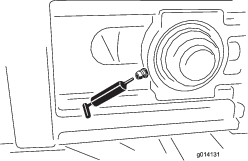
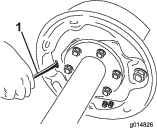
Remove the adjusting hole cover from the slot at the back side of the brake-backing plate.
-
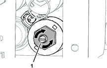
With a screwdriver, rotate the star wheel of the adjuster assembly to expand the brake shoes (Figure 51).
Adjust the brake shoes out until the pressure of the linings against the drum makes the wheel difficult to turn.
-
Rotate the star wheel in the opposite direction until the wheel turns freely with a slight drag on the lining.
-
Install the adjusting hole cover.
-
Repeat steps 2 through each brake.
Inspecting the Brake Shoes and Linings
| Maintenance Service Interval | Maintenance Procedure |
|---|---|
| Monthly |
|
When a brake shoe becomes worn, replace both shoes on each brake, and both brakes on the same axle. This ensures that the brakes remain balanced.
Replace the brake linings under the following conditions:
-
They are worn to 1/16 inch (1.6 mm) or less remaining thickness.
-
They are contaminated with grease or oil.
-
They are abnormally scored or gouged.
Note: Hairline heat cracks are normal in the brake linings.
Brake Cleaning and Inspection
| Maintenance Service Interval | Maintenance Procedure |
|---|---|
| Yearly |
|
-
Change magnets and shoes when they become worn or scored.
-
Clean the backing plate, magnet arm, magnet, and brake shoes with an automotive brake cleaner.
-
Ensure that all parts removed are replaced in the same brake and drum assembly that they were removed from.
-
Inspect the magnet arm for any loose or worn parts.
-
Check the shoe return springs, the hold down springs, and the adjuster springs for stretch or deformation and replace them if required.
Caution
Brake dust can be hazardous to your health if inhaled; take the following precautions when servicing brakes:
-
Do not create or breathe dust.
-
Do not machine, file, or grind the brake linings.
-
Do not use compressed air or dry brushing for cleaning.
-
Brake Lubrication
Before reassembling the electric brakes, apply a light film of anti-seize compound, or grease such as Lubriplate™ on the following:
-
Brake anchor pin
-
Actuating arm bushing and pin
-
Areas on the backing plate that are in contact with the brake shoes and magnet lever arm
-
Actuating block on the actuating arm
Important: Do not allow grease to contact the brake linings, drums, or magnets.
Inspecting the Magnets
The electromagnets of the brakes are designed to provide the proper input force and friction.
Inspect the magnets regularly, and replace if they become unevenly worn. Use a tool with a straight edge to check wear.
Even if the wear is normal, replace the magnets if any part of the magnet coil is visible through the friction material on the magnet face. Replace the magnets in pairs (both sides of an axle).
When replacing the magnets, also resurface the drum armature surface.
Hydraulic System Maintenance
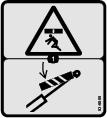
Hydraulic System Safety
-
Seek immediate medical attention if fluid is injected into skin. Injected fluid must be surgically removed within a few hours by a doctor.
-
Ensure that all hydraulic-fluid hoses and lines are in good condition and all hydraulic connections and fittings are tight before applying pressure to the hydraulic system.
-
Keep your body and hands away from pinhole leaks or nozzles that eject high-pressure hydraulic fluid.
-
Use cardboard or paper to find hydraulic leaks.
-
Safely relieve all pressure in the hydraulic system before performing any work on the hydraulic system.
Hydraulic Fluid Specification
| Toro Premium Transmission/Hydraulic Tractor Fluid (Available in 5 gallon pails or 55 gallon drums. See parts catalog or Toro distributor for part numbers.) |
Alternate fluids: If the Toro fluid is not available, other petroleum-based Universal Tractor Hydraulic Fluids (UTHF) may be used provided its specifications fall within the listed range for all the following material properties and it meets industry standards. We do not recommend the use of synthetic fluid. Consult with your lubricant distributor to identify a satisfactory product.
Note: Toro will not assume responsibility for damage caused by improper substitutions, so use only products from reputable manufacturers who will stand behind their recommendation.
| Material Properties: | |||
| Viscosity, ASTM D445 | cSt @ 40°C 55 to 62 | ||
| Viscosity Index ASTM D2270 | 140 to 152 | ||
| cSt @ 100°C 9.1 to 9.8 | |||
| Pour Point, ASTM D97 | -35°F to -46°F | ||
| Industry Specifications: | |||
| API GL-4, AGCO Powerfluid 821 XL, Ford New Holland FNHA-2-C-201.00, Kubota UDT, John Deere J20C, Vickers 35VQ25, and Volvo WB-101/BM | |||
Checking the Hydraulic System
| Maintenance Service Interval | Maintenance Procedure |
|---|---|
| Before each use or daily |
|
-
Check the hydraulic system for oil leaks.
If you find a leak, tighten the fitting, or replace or repair the damaged part.
-
Check the hydraulic hoses for wear or damage.
Replace worn or damaged hoses
-
Check the hydraulic-fluid level of the traction unit.
Add hydraulic-fluid level to the reservoir if needed; refer to the Operator’s Manual for your traction unit.
Optional Attachments
Checking the Optional Attachments
| Maintenance Service Interval | Maintenance Procedure |
|---|---|
| Before each use or daily |
|
-
Check that the quick attach brackets are secure and that the safety clips are installed.
Replace any missing safety clips.
-
Check that the optional attachment is securely clamped and does not move or slide out.
Adjust clamps if required.
-
Check the paddles on the Twin Spinner disks for wear.
Replace the paddles when they wear thin.
-
Check the Twin Spinner housing for signs of cracking or corrosion.
Maintaining the Conveyor Belt
Checking the Conveyor Belt and Rollers
| Maintenance Service Interval | Maintenance Procedure |
|---|---|
| Every 40 hours |
|
| Monthly |
|
-
Check that the conveyor belt tracks straight on the rollers and it does not slip.
Adjust the conveyor belt tracking if required; refer to Adjusting the Conveyor Belt Tracking.
-
Check that the idler rollers between the front and rear rollers are not bent or seized.
Replace or repair worn or damaged idler rollers if required.
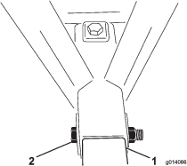
Adjusting the Conveyor Belt Tracking
If the conveyor belt is not centered and tracks to one side, it needs to be adjusted (Figure 52). The best time to do this is between loads during operation.
-
Go to the rear of the machine and determine which side of the belt is touching.
-
Go to the front on the same side, loosen the locking nut, and tighten the adjuster nut by one quarter turn.
-
Tighten both locking nuts before running the machine.
-
Load the machine with material and run the load through until empty. Repeat multiple times.
-
Stop the belt and go to the rear of the machine to observe the results.
You may need to repeat the above steps several times until the belt begins to move and track properly.
Note: The belt may move slightly depending on the type of load and its position. If the belt is not touching the side rails, you do not need to track the belt.
Important: Do not adjust the rear drive roller of the conveyor belt. It is set to factory specifications. Contact your authorized Toro distributor it needs an adjustment.
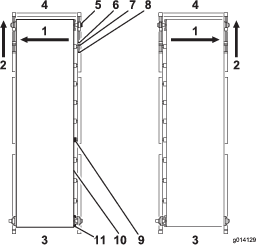
Adjusting the Conveyor Belt Tension
Check and adjust the belt tension frequently (Figure 52). All rubber conveyor belts stretch, especially when they are new or have not been used for a while.
-
Park the machine on level ground with the rear gate and feed gate at least 6.25 mm (1/4 inch) off the floor (depending on the material).
-
Fully load the machine with sand that you expect the machine to use.
-
Remove the black front covers on either side of the machine.
-
Using two wrenches, hold the end of the tensioner rod stationary, while loosening the locking nut closest to the end of the rod.
-
Move the locking nut back 2 to 5 cm (1 to 2 inches).
Warning
Operating the conveyor belt with the guards and covers removed can cause serious injury.
Use extreme caution around moving parts with safety guards removed.
-
Turn on the conveyor belt.
-
If belt slips, tighten the tension bolts evenly (with machine off) half a turn and check if the belt slips again. Continue until the belt moves without any slippage.
-
Give both tensioning bolts another half turn. At this point you should have proper tension.
-
To verify belt tension, look underneath the machine at the chassis cross member. The middle of the belt should just clear the chassis cross member when the machine is in the down position. If the middle of the belt is touching the cross member, tighten both tensioning bolts another quarter of a turn.
Important: Be patient. Do not over-tension the belt.
Important: Do not use air tools on the belt tensioning bolts.
Changing the Conveyor Belt
Read these instructions before removing the belt. If the belt is destroyed, use a knife to cut the belt in an undamaged area. If you intend to make a warranty claim, the belt supplier must inspect the belt to evaluate the damage and make recommendations for a replacement.
Removing the Belt
-
Remove the black safety covers located on the four outer corners of the machine.
-
Remove the guides for the inner rubber liner from the front and both sides of the hopper, with the metal rails attached.
-
Remove the silicone sealer on the rear of the metal rails (but remember to apply the silicone sealer when re installing them).
-
At both front corners, use two wrenches to hold the end of the tensioner rod stationary.
-
Loosen the nut closest to the end of the tensioning rod.
-
Move the inside adjusting nut back until the tensioning rod clears the pillow block bearing.
Note: The front idler roller is supported by two pillow block bearings sitting in an upper and lower guide (one set on each side of the machine).
-
Support the front idler roller.
-
Go to the right front corner and remove the locking collar that holds the pillow block bearing on the shaft. Do this by backing off the set screws and turning the locking collar counterclockwise. Using a hammer and punch, tap the locking collar counterclockwise until it releases from the shaft.
-
Repeat this step for the left front corner.
-
Remove the pillow block bearings by sliding the idler roller back so the pillow block bearings slide out of their guides.
-
Remove the two safety brackets and slide the roller down through the open hole.
-
Go to the rear of the machine and loosen the tensioning sprocket.
-
Remove the chain from the drive sprocket.
-
Loosen the set screws on the drive sprocket and remove the drive sprocket and key from the drive roller shaft.
-
Support the rear drive roller.
Important: Do not disturb the rear roller adjustment bracket assembly. It is designed to adjust the rear roller automatically if the belt is not tracking accurately.
-
Remove the four bolts in the flange bearings on both sides.
-
Remove the locking collars next to the flange bearings on the shaft, and slide both bearings off the shaft.
-
Remove the two option attachment brackets (Figure 53).
-
Lower the drive roller down through the slots.
-
Remove the rear gate for a better view.
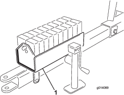
-
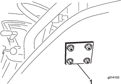
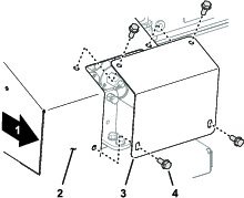
Note the position of the cartridge inside the hopper, so that you can re install it in the same position and direction. It is bolted in six places along the side of the machine (three 4 bolt plates on each side).
-
Secure the cartridge by using straps from a lifting device on each of the four corners.
-
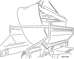
Remove the 24 bolts to release the cartridge (Figure 54).
-
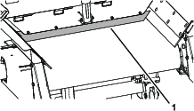
Remove the cartridge by lifting it out from the top of the machine. Place it on the ground (Figure 55).
Installing the Belt
To install a new belt, reverse the above instructions, but keep in mind the following important notes and instructions.
Important: The conveyor belt is designed to work primarily in one direction. Ensure that the painted arrow in the middle of the belt is pointing toward the rear of the machine (looking down from above).
Note: Before sliding the rear drive roller back up through the slot and into place, ensure that you have already installed the four bolts (from the inside facing out) for connecting the pillow block bearings. Otherwise, you must remove the drive roller to gain enough clearance to install these bolts.
-
When installing the rear drive roller, ensure that the shaft connecting to the motor is on the left side. It has a keyhole cut into it for securing the drive sprocket.
-
Before applying tension with the tensioner rods at the front of the machine, use your hands to manually center the belt at the front and rear.
-
Track and tension the belt by following the instructions in Adjusting the Conveyor Belt Tracking and Adjusting the Conveyor Belt Tension.
-
The front idler and rear drive rollers provide excellent traction for pulling the belt under load.
Important: Do not overtighten or stretch the belt.
-
Apply silicone sealer to the rear side of the metal rails and at the two front corners of the floor where the rails meet. The sealer deflects any material from getting past the rails.
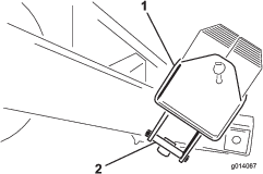
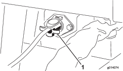
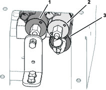
Adjusting the Conveyor Drive Chain Tension
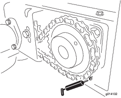
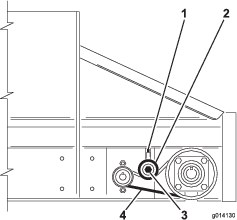
If the conveyor drive chain is loose, it needs to be tightened (Figure 56).
-
Shut off the engine of the traction unit and engage the parking brake.
-
Remove the rear conveyor drive guard.
-
Loosen the bolt that goes through the tensioner sprocket.
-
Tighten the positive locking screw using moderate force.
-
Tighten the tensioner sprocket bolt.
Important: Do not over tension the chain. Leave just enough tension to take up the extra slack.
-
Check that the chain is sufficiently lubricated, and the sprockets are secure to the shafts.
-
Replace the rear conveyor drive guard.
Maintaining the Hopper and Rear Gate
Checking the Conveyor Seals and Rear Gate Seal
| Maintenance Service Interval | Maintenance Procedure |
|---|---|
| Before each use or daily |
|
Check all rubber seals for damage or wear.
Replace or repair the seals if they are damaged or excessively worn.
Checking the Rear Gate
| Maintenance Service Interval | Maintenance Procedure |
|---|---|
| Before each use or daily |
|
-
Check that the rear gate closes and latches securely.
-
Check that the adjustable section of the rear gate opens and closes without sticking.
Cleaning
Washing the Machine
Salts, road tar, tree sap, fertilizers, or chemicals may damage the painted finish of the machine. Wash off these deposits as soon as possible with detergent and water. Additional cleaners or solvents may be needed, but ensure that they are safe for painted surfaces.
Warning
Flammable fluids and cleaners with toxic vapors are hazardous to your health.
Do not use flammable fluids or cleaners with toxic vapors. Follow the manufacturer’s recommendations.
Important: Do not use a high-pressure washer. This can remove paint, safety decals, and grease, and can also damage components.
-
Remove the option before cleaning and wash it separately.
-
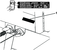
Remove the handheld remote.
-
Wash the body of the machine with warm water and a mild detergent
-
Completely rinse off the detergent residue with clean water before it dries.
-
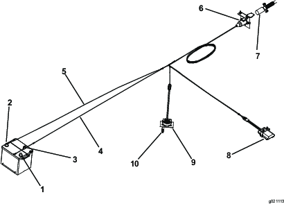
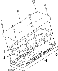
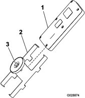
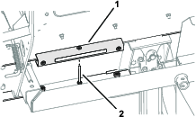
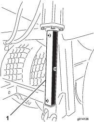
Remove the belt cleaning scraper assembly from the rear of the machine (Figure 57).
-
Raise the back of the machine if needed.
-
Fully open the rear gate and spray water inside the hopper assembly and the rear gate area. Inspect the side seals and replace if necessary.
-
Inspect the hopper, bottom guard, conveyor belt, bed, and rollers to ensure that all trapped material is gone.
-
Lower the machine to the normal operating position.
-
If removed, install the belt cleaning scraper assembly.
Ensure that the scraper is as vertical as possible but contacts the belt.