| Maintenance Service Interval | Maintenance Procedure |
|---|---|
| Before each use or daily |
|
Introduction
This machine is a ride-on, rotary-blade lawn mower intended for used by professional operators in commercial applications. It is designed primarily for mowing grass on well-maintained lawns in parks, golf courses, sports fields, along roadways, and on commercial grounds. The machine is not designed for mowing brush or for agricultural uses.
Read this information carefully to learn how to operate and maintain your product properly and to avoid injury and product damage. You are responsible for operating the product properly and safely.
Visit www.Toro.com for product safety and operation training materials, accessory information, help finding a dealer, or to register your product.
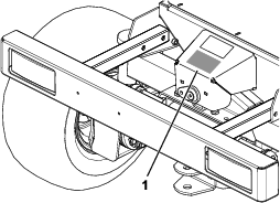
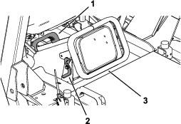
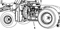
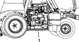
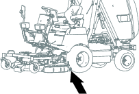
Whenever you need service, genuine Toro parts, or more information, contact an Authorized Service Dealer or Toro Customer Service and have the model and serial numbers of your product ready. Figure 1 identifies the location of the model and serial numbers on the product. Write the numbers in the space provided.
This manual identifies potential hazards and has safety messages identified by the safety-alert symbol (Figure 2), which signals a hazard that may cause serious injury or death if you do not follow the recommended precautions.

This manual uses 2 words to highlight information. Important calls attention to special mechanical information and Note emphasizes general information worthy of special attention.
This product complies with all relevant European directives; for details, please see the separate product specific Declaration of Conformity (DOC) sheet.
It is a violation of California Public Resource Code Section 4442 or 4443 to use or operate the engine on any forest-covered, brush-covered, or grass-covered land unless the engine is equipped with a spark arrester, as defined in Section 4442, maintained in effective working order or the engine is constructed, equipped, and maintained for the prevention of fire.
The enclosed engine owner's manual is supplied for information regarding the US Environmental Protection Agency (EPA) and the California Emission Control Regulation of emission systems, maintenance, and warranty. Replacements may be ordered through the engine manufacturer.
Warning
CALIFORNIA
Proposition 65 Warning
Diesel engine exhaust and some of its constituents are known to the State of California to cause cancer, birth defects, and other reproductive harm.
Battery posts, terminals, and related accessories contain lead and lead compounds, chemicals known to the State of California to cause cancer and reproductive harm. Wash hands after handling.
Use of this product may cause exposure to chemicals known to the State of California to cause cancer, birth defects, or other reproductive harm.
Safety
General Safety
This product is capable of amputating hands and feet and of throwing objects. Always follow all safety instructions to avoid serious personal injury.
-
Read and understand the contents of this Operator’s Manual before starting the engine.
-
Use your full attention while operating the machine. Do not engage in any activity that causes distractions; otherwise, injury or property damage may occur.
-
Do not operate the machine without all guards and other safety protective devices in place and functioning properly on the machine.
-
Keep your hands and feet away from rotating parts. Keep clear of the discharge opening.
-
Keep bystanders and children out of the operating area. Never allow children to operate the machine.
-
Shut off the engine, remove the key, and wait for all movement to stop before you leave the operator’s position, Allow the machine to cool before adjusting, servicing, cleaning, or storing it.
Improperly using or maintaining this machine can result in injury.
To reduce the potential for injury, comply with these safety instructions
and always pay attention to the safety-alert symbol  , which means Caution, Warning,
or Danger—personal safety instruction. Failure to comply with
these instructions may result in personal injury or death.
, which means Caution, Warning,
or Danger—personal safety instruction. Failure to comply with
these instructions may result in personal injury or death.
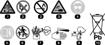
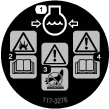
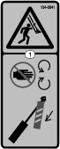
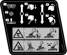
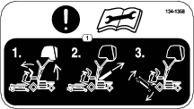
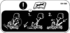
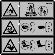
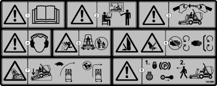
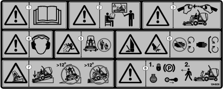
Safety and Instructional Decals
 |
Safety decals and instructions are easily visible to the operator and are located near any area of potential danger. Replace any decal that is damaged or missing. |


Affix for non-CE machines

Affix for non-CE machines

Affix over Part No. 134-0539 for non-CE machines
Setup
Note: Determine the left and right sides of the machine from the normal operating position.
Charging the Battery
-
Connect a 3 to 4 A battery charger to the battery posts. Charge the battery at a rate of 3 to 4 A until the specific gravity of the electrolyte is 1.250 or higher and the temperature of the battery is at least 16°C (60°F), with all cells freely discharging gas.
-
When the battery is charged, disconnect the charger from the electrical outlet and then disconnect the charger from the battery posts.
Note: Incomplete charging may result in gassing of the battery and the overflow of battery acid, causing corrosive damage to the machine.
Checking the Fluid Levels
-
Check the engine-oil level before you start the engine; refer to Checking the Engine-Oil Level.
-
Check the coolant level before you start the engine; refer toChecking the Cooling System and Coolant Level.
-
Check the level of the hydraulic-fluid level before you start the engine; refer to Checking the Hydraulic-Fluid Level.
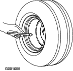
Checking the Air Pressure in the Tires
Front and rear tires air pressure specification: 140 kPa (20 psi).
Caster tires air pressure specification: 150 kPa (21 psi).
Check the air pressure in the front and rear tires before the engine is first started.
Note: The tires may be over-inflated or under-inflated for shipping; therefore, you may have to adjust the air pressure in the tires.
Mounting the Mower Deck
-
Remove the traction unit and mower deck from the shipping pallet.
-
Install the mower deck to the traction unit; refer to Installing the Mower Deck.
Product Overview
Note: Determine the left and right sides of the machine from the normal operating position.
Dash Panel
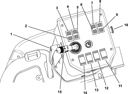
Steering-Column Tilt Lever
Rotate the steering-column tilt lever (Figure 6) counterclockwise to release the steering column, and move it to your desired position.
Rotate the lever clockwise to secure your desired position.
Charge Indicator
The charge indicator (Figure 6) illuminates if electrical charging system is operating below the normal operating range. Check and/or repair the electrical charging system.
Glow-Plug Indicator
The glow-plug indicator (Figure 6) glows red when the glow plugs are activated.
Oil-Pressure Warning Indicator
The oil-pressure warning indicator (Figure 6) illuminates if the engine-oil pressure drops below a safe level while the engine is running. If the light flickers or remains on, stop the machine, shut off the engine, and check the oil level. If the oil level is within the acceptable range, but the light does not go out as the engine runs, shut off the engine immediately and contact your authorized Toro distributor for assistance.
Check the operation of warning light as follows:
-
Engage the parking brake.
-
Turn the key switch to the ON/PREHEAT position, but do not start the engine.
Note: The oil-pressure light should glow red. If the light does not function, either a bulb is burned out or there is a malfunction in the system which must be repaired.
Air-Filter Restriction Indicator
The air-filter restriction indicator (Figure 6) illuminates if the air filter needs to be cleaned or replaced; refer to Servicing the Air-Cleaner Filters.
Road-Lights Indicator
The road-light indicator (Figure 6) illuminates green on low beam and blue on high beam.
Raised-Hopper Indicator
The raised-hopper indicator (Figure 6) illuminates if the hopper raises from the grass-collecting position.
Lower the hopper to turn the indicator off.
Parking-Brake Indicator
The parking-brake indicator (Figure 6) illuminates if the parking brake is engaged.
PTO Switch
The PTO switch (Figure 6) has 2 positions: OUT (engaged) and IN (disengaged). Pull out the PTO switch to engage the implement or mower-deck blades. Push in the button to disengage the implement operation.
Note: If you leave the operator’s seat while the PTO switch is in the ON position, the machine automatically shuts off the engine after a 1-second delay; refer to Resetting the PTO Function.
Hazard-Lights Switch
Push the hazard-lights switch (Figure 6) forward to turn the hazard lights on.
Push the switch rearward to turn the hazard lights off.
Differential-Lock Switch
Push the differential-lock switch (Figure 6) forward to engage the differential lock.
Push the switch rearward to disengage the differential lock.
Radiator Fan-Reversal Switch
Push the fan-reversal switch (Figure 6) forward to engage the fan-reversal cycle for the radiator.
Beacon-Light Switch
Push the beacon-light switch (Figure 6) forward to turn the beacon light on.
Push the switch rearward to turn the beacon light off.
Turn Signal and Road Lights
Rotate the lever (Figure 6) forward to the first-slot position to turn the side lights on.
Rotate the lever forward to the second-slot position to turn the low beam lights on. The green road-light indicator will illuminate.
Push down on the lever to switch the high beam lights on. The blue road-light indicator will illuminate.
From the low beam position, pull the lever up to flash the high beam lights.
Rotate the lever rearward to turn the lights off.
Push the lever forward to turn on the right-turn signal. Pull the lever back to turn on the left-turn signal.
Horn Button
Push the horn button inward to activate the horn (Figure 6).
Brake Pedal
Use the brake pedal (Figure 7) to stop or slow the machine.
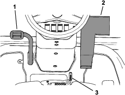
Traction Pedal
Use the traction pedal (Figure 7) to move the machine forward or rearward. Press the top of the pedal to move the machine forward and the bottom to move it rearward. Ground speed depends on how far you press the pedal. For maximum ground speed, move the throttle lever to the FAST position, and fully press traction pedal. The maximum forward speed is approximately 14 km/h (9 mph). To get maximum power under a heavy load or when ascending a hill, move the throttle lever to the FAST position and keep the engine speed (rpm) high, while pressing traction pedal gradually. When the engine speed begins to decrease, release the traction pedal slightly to allow the engine speed to increase.
Parking-Brake Lock
While pressing the brake pedal, push the parking-brake lock (Figure 7) forward to lock the parking brake in the engaged position. To disengage the parking brake, push the brake pedal forward. The parking-brake lock automatically disengages.
Fuel Gauge
The fuel gauge (Figure 8) indicates the level of fuel remaining in the fuel tank.
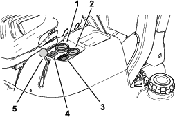
Engine-Temperature Gauge
The engine-temperature gauge (Figure 8) indicates the current temperature of the engine.
Height-of-Cut Switch
Use the height-of-cut switch (Figure 8) to raise or lower your desired height of cut.
Height-of-Cut Gauge
The height-of-cut gauge (Figure 9) indicates the nominal mower deck cutting height.
Throttle Lever
Use the throttle lever (Figure 8) to control the engine speed. Moving the throttle lever forward toward the FAST position increases the engine speed. Moving the throttle lever rearward toward the SLOW position decreases the engine speed. The throttle lever controls the speed of the blades and, with the traction pedal, controls the ground speed of the machine.
Hour Meter/Service Due Indicator
The hour meter (Figure 8) records and displays accumulated hours of engine operation.
The service due indicator displays the number of hours until the next engine oil and filter change.
Note: The indicator flashes automatically with “OIL CHANGE” when you need to change the engine oil and filter.
The service due indicator also displays the number of hours until you need to grease the machine.
Note: The indicator flashes automatically with “LUBE” when you need to lubricate the machine.
Push the button ON the hour meter/service due indicator to select the function on the screen.
Important: During the first 50 hours while in the oil change mode, take care to not inadvertently hold the button of the hour meter longer than 6-seconds. Holding the button longer than 6-seconds will set the oil service interval from 50 hours to 250 hours.
After changing the engine oil and filter or lubricating the machine and mower deck, perform the following:
-
Push the button until you reach the desired screen.
-
Push and hold the button for 6 seconds until the indicator stops flashing.
Note: You cannot reset the total working hours of the machine.
Deck Lift Lever
Pull the lock collar on the deck lift lever (Figure 10) up and move the lever rearward to raise the mower deck.
Pull the lock collar on the deck lift lever (Figure 10) up and move the lever forward to lower the deck and allow it to float.
Important: To avoid damaging the deck-lift system, set the deck lift lever to the forward (FLOAT) position whenever you drive the machine with the deck on the ground.
Note: Lower the deck and hopper whenever you are not using the machine.
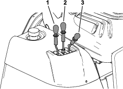
Hopper Lift Lever
Pull the lock collar on the hopper lift lever (Figure 10) up and move the lever rearward to raise the hopper.
Pull the lock collar on the hopper lift lever up and move the lever forward to lower the hopper.
Hopper Dump Lever
Pull the lock collar on the hopper dump lever (Figure 10) up and move the lever rearward to dump the clippings from the hopper.
Pull the lock collar on the hopper dump lever up and move the lever forward to close the hopper after dumping.
Key Switch
The key switch has 4 positions: OFF, LIGHTS ON, ON/PREHEAT, and START.
Note: The LIGHTS ON position controls the work light.When you turn the key switch from the OFF position to the LIGHTS ON position, the work light illuminates.When you turn key switch from the ON/PREHEAT position to the LIGHTS ON position, the engine continues to run and light illuminates.
Note: If the engine stops running and the key switch is in the LIGHTS ON or the ON/PREHEAT position, and you leave the operator's seat, after a short delay a buzzer will sound to alert you to turn the key to the OFF position.
Note: Specifications and design are subject to change without notice.
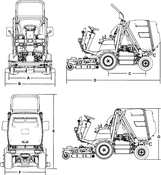
| Description | Figure 12 Reference | Dimension or Weight |
| Height with roll bar raised | E | 207 cm (81-1/2 inches) |
| Height with roll bar lowered | G | 166 cm (65-1/2 inches) |
| Overall length | D | 291 cm (114-1/2 inches) |
| Overall width | B | 143 cm (56-1/2 inches) |
| Wheel-base length | C | 119 cm (47 inches) |
| Front-wheel tread width | A | 95 cm (37 inches) |
| Rear-wheel tread width | F | 96 cm (38 inches) |
| Ground clearance | 15 cm (6 inches) | |
| Net weight (with mower deck) | 1005 kg (2,216 lb) | |
| Net weight (without mower deck) | 835 kg (1,841 lb) | |
| Maximum gross weight | 1190 kg (2,624 lb) | |
| Front axle weight limit | 1000 kg (2,205 lb) | |
| Rear axle weight limit | 500 kg (1,102 lb) |
Attachments/Accessories
A selection of Toro approved attachments and accessories is available for use with the machine to enhance and expand its capabilities. Contact your Authorized Service Dealer or authorized Toro distributor or go to www.Toro.com for a list of all approved attachments and accessories.
Use only genuine Toro replacement parts and accessories. Replacement parts and accessories made by other manufacturers could be dangerous, and such use could void the product warranty.
Operation
Before Operation
Before Operation Safety
General Safety
-
Never allow children or untrained people to operate or service the machine. Local regulations may restrict the age of the operator. The owner is responsible for training all operators and mechanics.
-
Become familiar with the safe operation of the equipment, operator controls, and safety signs.
-
Shut off the engine, remove the key, and wait for all movement to stop before you leave the operator’s position, Allow the machine to cool before adjusting, servicing, cleaning, or storing it.
-
Know how to stop the machine and shut off the engine quickly.
-
Check that operator-presence controls, safety switches, and guards are attached and functioning properly. Do not operate the machine unless they are functioning properly.
-
Before mowing, always inspect the machine to ensure that the blades, blade bolts, and cutting assemblies are in good working condition. Replace worn or damaged blades and bolts in sets to preserve balance.
-
Inspect the area where you will use the machine and remove all objects that the machine could throw.
Fuel Safety
-
Use extreme care in handling fuel. It is flammable and its vapors are explosive.
-
Extinguish all cigarettes, cigars, pipes, and other sources of ignition.
-
Use only an approved fuel container.
-
Do not remove the fuel cap or fill the fuel tank while the engine is running or hot.
-
Do not add or drain fuel in an enclosed space.
-
Do not store the machine or fuel container where there is an open flame, spark, or pilot light, such as on a water heater or other appliance.
-
If you spill fuel, do not attempt to start the engine; avoid creating any source of ignition until the fuel vapors have dissipated.
Performing Daily Maintenance
Before starting the machine each day, perform the Each Use/Daily procedures listed in Daily Maintenance Checklist.
Checking the Air Pressure in the Tires
Front and rear tires air pressure specification: 140 kPa (20 psi).
Caster tires air pressure specification: 150 kPa (21 psi).
Danger
Low tire pressure decreases machine side-hill stability. This could cause a rollover, which may result in personal injury or death.
Do not under-inflate the tires.
Check the air pressure in the front and rear tires. Add or remove air as needed to set the air pressure in the tires to the tire air pressure specification.
Important: Maintain pressure in all tires to ensure a good quality of cut and proper machine performance.Check the air pressure in all the tires before operating the machine.
Checking the Safety-Interlock System
The purpose of the safety-interlock system is to prevent the engine from cranking or starting unless the traction pedal is in neutral, the PTO switch is in the OFF position, the parking brake is engaged, or the operator is in the seat.
In addition, the engine should shut off when:
-
The operator leaves the seat with the PTO switch in the ON position;
-
The operator leaves the seat with the traction pedal out of neutral;
-
The traction pedal is pressed with the parking brake engaged.
Caution
If the safety-interlock switches are disconnected or damaged, the machine could operate unexpectedly, causing personal injury.
-
Do not tamper with the interlock switches.
-
Check the operation of the interlock switches daily and replace any damaged switches before operating the machine.
Checking the Engine Cranking Safety-Interlock System
| Maintenance Service Interval | Maintenance Procedure |
|---|---|
| Before each use or daily |
|
Check the operation of the safety-interlock switches by ensuring the following:
| Conditions | Result |
|---|---|
| Parking brake disengaged | The engine should not crank. |
| Traction pedal in neutral | |
| PTO switch in the OFF position | |
| No operator in the seat | |
| Parking brake disengaged | The engine should crank. |
| Traction pedal in neutral | |
| PTO switch in the OFF position | |
| Operator in the seat | |
| Parking brake disengaged | The engine should not crank. |
| Traction pedal pushed down | |
| PTO switch in the OFF position | |
| Operator in the seat | |
| Parking brake engaged | The engine should not crank. |
| Traction pedal pushed down | |
| PTO switch in the OFF position | |
| Operator in the seat | |
| Parking brake engaged | The engine should crank. |
| Traction pedal in neutral | |
| PTO switch in the OFF position | |
| No operator in the seat |
Checking the Engine Shut-Off Safety-Interlock System
| Maintenance Service Interval | Maintenance Procedure |
|---|---|
| Before each use or daily |
|
Before doing the following checks, perform the following:
-
Sit in the operator’s seat.
-
Engage the parking brake.
-
Move the traction pedal to neutral.
-
Disengage the PTO.
-
Start the engine.
-
Disengage the parking brake.
Check the operation of the safety-interlock switches by ensuring the following:
| Conditions | Result |
|---|---|
| Parking brake disengaged | The engine should shut off. |
| Operator rises slightly from the seat | |
| Parking brake engaged | The engine should continue to run. |
| Operator rises slightly from the seat | |
| Parking brake engaged | The engine should shut off. |
| Operator in the seat | |
| Traction pedal pushed down | |
| Parking brake disengaged | The engine should continue to run. |
| Operator in the seat | |
| Traction pedal pushed down |
Checking the PTO Safety-Interlock System
| Maintenance Service Interval | Maintenance Procedure |
|---|---|
| Before each use or daily |
|
Before doing the following checks, perform the following:
-
Sit in the operator’s seat.
-
Engage the parking brake.
-
Move the traction pedal to neutral.
-
Disengage the PTO.
-
Start the engine.
-
Disengage the parking brake.
Check the operation of the safety-interlock switches by ensuring the following:
| Conditions | Result |
|---|---|
| PTO switch in the ON position and the mower deck running | The engine and the mower deck should shut off. |
| Operator rises slightly from the seat | |
| PTO switch in the ON position and the mower deck running | The mower deck should shut off. |
| Raise the hopper |
Checking the Back-Up Alarm Safety-Interlock System
| Maintenance Service Interval | Maintenance Procedure |
|---|---|
| Before each use or daily |
|
Check the operation of the safety-interlock switches by ensuring the following:
| Conditions | Result |
|---|---|
| Key in the RUN position | The back-up alarm should sound. |
| Traction pedal in reverse |
Adding Fuel
Use only clean, fresh diesel fuel or biodiesel fuels with low (<500 ppm) or ultra low (<15 ppm) sulfur content. The minimum cetane rating should be 40. Purchase fuel in quantities that can be used within 180 days to ensure fuel freshness.
Fuel tank capacity: 41 L (10.8 US gallons)
Use summer-grade diesel fuel (No. 2-D) at temperatures above -7°C (20°F) and winter-grade (No. 1-D or No. 1-D/2-D blend) below that temperature. Using winter-grade fuel at lower temperatures provides lower flash point and cold flow characteristics which will ease starting and reduce fuel filter plugging.
Using summer-grade fuel above -7°C (20°F) will contribute toward longer fuel pump life and increased power compared to winter-grade fuel.
Important: Do not use kerosene or gasoline instead of diesel fuel. Failure to observe this caution will damage the engine.
Biodiesel Ready
This machine can also use a biodiesel blended fuel of up to B20 (20% biodiesel, 80% petrodiesel). The petrodiesel portion should be low or ultra low sulfur. Observe the following precautions:
-
The biodiesel portion of the fuel must meet specification ASTM D6751 or EN14214.
-
The blended fuel composition should meet ASTM D975 or EN590.
-
If you spill biodiesel fuel blends, the fuel may damage painted surfaces.
-
Use B5 (biodiesel content of 5%) or lesser blends in cold weather.
-
Monitor the seals, hoses, and gaskets in contact with fuel as they may degrade over time.
-
Expect fuel filter plugging for a time after converting to biodiesel blends.
-
Contact your authorized Toro distributor if you want more information on biodiesel.
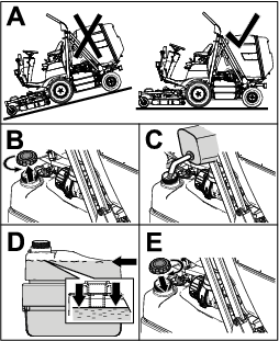
Filling the Fuel Tank
Note: If possible, fill the fuel tank after each use; this minimizes possible buildup of condensation inside the fuel tank.
Adjusting the Rollover Protection System (ROPS)
Warning
To avoid injury or death from rollover, keep the roll bar in the raised locked position and use the seat belt.
Ensure that the seat is secured with the seat latch.
Warning
There is no rollover protection when the roll bar is in the down position.
-
Do not operate the machine on uneven ground or on a hill side with the roll bar in the down position.
-
Lower the roll bar only when absolutely necessary.
-
Do not wear the seat belt when the roll bar is in the down position.
-
Drive slowly and carefully.
-
Raise the roll bar as soon as clearance permits.
-
Check carefully for overhead clearances (i.e., branches, doorways, electrical wires) before driving under any objects and do not contact them.
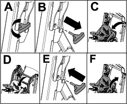
Lowering the Roll Bar
Important: Lower the roll bar only when absolutely necessary.
-
Park the machine on a level surface.
-
Disengage the PTO, lower the mower deck, and engage the parking brake.
-
Shut off the engine and remove the key.
-
Tilt the seat forward (Figure 15).
-
Remove the knob pins from the roll bar (Figure 15).
-
Lower the roll bar and secure it in place with the knob pins (Figure 15).
-
Tilt the seat rear to the locked position (Figure 15).
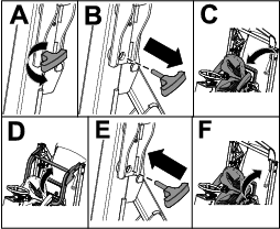
Raising the Roll Bar
-
Park the machine on a level surface.
-
Disengage the PTO, lower the mower deck, and engage the parking brake.
-
Shut off the engine and remove the key.
-
Tilt the seat forward (Figure 16).
-
Remove the knob pins from the roll bar (Figure 16).
-
Raise the roll bar and secure it in place with the knob pins (Figure 16).
-
Tilt the seat rear to the locked position (Figure 16).
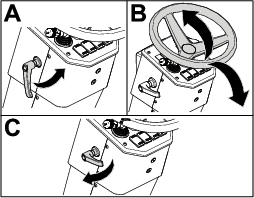
Adjusting the Tilt-Steering Column
Adjust the tilt-steering column to your desired position as shown in Figure 17.
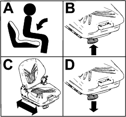
Positioning the Seat
The seat moves forward and backward. Position the seat where you have the best control of the machine and are most comfortable.
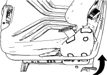
To adjust, pull the lever upward and move the seat forward or rearward (Figure 18).
Adjusting the Seat Suspension
-
Pull the seat-suspension lever out (Figure 19).
-
While sitting in the seat, adjust the seat suspension as follows:
-
For firmer suspension, pull the seat-suspension lever up as many times as necessary.
-
For softer suspension, push the seat-suspension lever down as many times as necessary.
-
-
When the arrow is in the middle, push the lever back in.
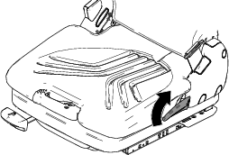
Tilting the Back of the Seat
Pull the lever (Figure 20) upward to tilt the back of the seat.
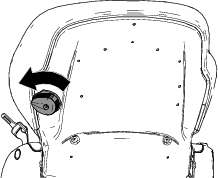
Adjusting the Seat Lumbar Support
Rotate the seat lumbar support (Figure 21) counterclockwise to increase the lumbar support.
Rotate the seat lumbar support clockwise to decrease the lumbar support.
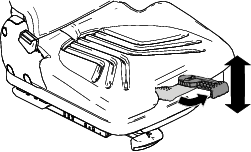
Tilting the Seat Forward
Lift the seat-tilt lever (Figure 22) upward and tilt the seat forward.
During Operation
During Operation Safety
General Safety
-
The owner/operator can prevent and is responsible for accidents that may cause personal injury or property damage.
-
Wear appropriate clothing, including eye protection; long pants; substantial, slip-resistant footwear; and hearing protection. Tie back long hair and do not wear loose clothing or loose jewelry.
-
Do not operate the machine while ill, tired, or under the influence of alcohol or drugs.
-
Use your full attention while operating the machine. Do not engage in any activity that causes distractions; otherwise, injury or property damage may occur.
-
Before you start the engine, ensure that all drives are in neutral, the parking brake is engaged, and you are in the operating position.
-
Do not carry passengers on the machine and keep bystanders and children out of the operating area.
-
Operate the machine only in good visibility to avoid holes or hidden hazards.
-
Avoid mowing on wet grass. Reduced traction could cause the machine to slide.
-
Keep your hands and feet away from rotating parts. Keep clear of the discharge opening.
-
Look behind and down before backing up to be sure of a clear path.
-
Use care when approaching blind corners, shrubs, trees, or other objects that may obscure your vision.
-
Stop the blades whenever you are not mowing.
-
Stop the machine, remove the key, and wait for all moving parts to stop before inspecting the attachment after striking an object or if there is an abnormal vibration in the machine. Make all necessary repairs before resuming operation.
-
Slow down and use caution when making turns and crossing roads and sidewalks with the machine. Always yield the right-of-way.
-
Disengage the drive to the cutting unit, shut off the engine, remove the key, and wait for all moving parts to stop before adjusting the height of cut (unless you can adjust it from the operating position).
-
Operate the engine only in well-ventilated areas. Exhaust gases contain carbon monoxide, which is lethal if inhaled.
-
Never leave a running machine unattended.
-
Before you leave the operator’s position, do the following:
-
Park the machine on a level surface.
-
Disengage the power takeoff and lower the attachments.
-
Engage the parking brake.
-
Shut off the engine and remove the key.
-
Wait for all movement to stop.
-
-
Operate the machine only in good visibility and appropriate weather conditions. Do not operate the machine when there is the risk of lightning.
-
Do not use the machine as a towing vehicle.
-
Use accessories, attachments, and replacement parts approved by Toro only.
Rollover Protection System (ROPS) Safety
-
The ROPS is an integral and effective safety device.
-
Do not remove any of the ROPS components from the machine.
-
Ensure that the seat belt is attached to the machine.
-
Pull the belt strap over your lap and connect the belt to the buckle on the other side of the seat.
-
To disconnect the seat belt, hold the belt, press the buckle button to release the belt, and guide the belt into the auto-retract opening. Ensure that you can release the belt quickly in an emergency.
-
Check carefully for overhead obstructions and do not contact them.
-
Keep the ROPS in safe operating condition by thoroughly inspecting it periodically for damage and keeping all the mounting fasteners tight.
-
Replace damaged ROPS components. Do not repair or alter them.
Additional ROPS Safety for Machines with a Foldable Roll Bar
-
Keep a folding roll bar in the raised and locked position, and wear your seat belt when operating the machine with the roll bar in the raised position.
-
Lower a folding roll bar temporarily only when necessary. Do not wear the seat belt when the roll bar is folded down.
-
Be aware that there is no rollover protection when a folded roll bar is in the down position.
-
Check the area that you will be mowing and never fold down a folding roll bar in areas where there are slopes, drop-offs, or water.
Slope Safety
-
Slopes are a major factor related to loss of control and rollover accidents, which can result in severe injury or death. You are responsible for safe slope operation. Operating the machine on any slope requires extra caution.
-
Evaluate the site conditions to determine if the slope is safe for machine operation, including surveying the site. Always use common sense and good judgment when performing this survey.
-
Review the slope instructions listed below for operating the machine on slopes and to determine whether you can operate the machine in the conditions on that day and at that site. Changes in the terrain can result in a change in slope operation for the machine.
-
Avoid starting, stopping, or turning the machine on slopes. Avoid making sudden changes in speed or direction. Make turns slowly and gradually.
-
Do not operate a machine under any conditions where traction, steering, or stability is in question.
-
Remove or mark obstructions such as ditches, holes, ruts, bumps, rocks, or other hidden hazards. Tall grass can hide obstructions. Uneven terrain could overturn the machine.
-
Be aware that operating the machine on wet grass, across slopes, or downhill may cause the machine to lose traction. Loss of traction to the drive wheels may result in sliding and a loss of braking and steering.
-
Use extreme caution when operating the machine near drop-offs, ditches, embankments, water hazards, or other hazards. The machine could suddenly roll over if a wheel goes over the edge or the edge caves in. Establish a safety area between the machine and any hazard.
-
Identify hazards at the base of the slope. If there are hazards, mow the slope with a pedestrian-controlled machine.
-
If possible, keep the cutting unit(s) lowered to the ground while operating on slopes. Raising the cutting unit(s) while operating on slopes can cause the machine to become unstable.
-
Use extreme caution with grass-collection systems or other attachments. These can change the stability of the machine and cause a loss of control.
Starting the Engine
Important: You may need to bleed the fuel system when starting a new machine, the engine no longer runs due to lack of fuel, or you have replaced or serviced the fuel system components.
-
Raise the roll bar and lock it into place.
-
Sit on the seat and fasten the seat belt.
-
Ensure that the parking brake is set and the PTO switch is in the OFF position.
-
Remove your foot from traction pedal and ensure that it is in neutral.
-
Rotate the key switch to the ON/PREHEAT position.
Note: An automatic timer then controls the preheat for a few seconds.
-
After preheating, rotate the key switch to the Start position, crank the engine for no longer than 15 seconds, and release the key when the engine starts.
Note: If additional preheating is required, turn the key to the OFF position, then to the ON/PREHEAT position. Repeat this process as required.
-
Move the throttle to idle speed or partial throttle and run the engine until it warms up.
Important: When you start the engine for the first time; or after you change the engine oil, hydraulic fluid, overhaul the engine, or replace traction components; operate the machine in forward and reverse for 1 to 2 minutes. Also, operate the lift lever and PTO lever to ensure that all parts are properly operating. Turn the power-steering wheel to the left and right to check the steering response. Then shut the engine off, check the fluid levels, and check for oil leaks, loose parts, and any other malfunctions.
Shutting Off the Engine
Caution
To prevent personal injury, shut the engine off and wait for all moving parts to stop before checking for oil leaks, loose parts, or other malfunctions.
-
Move the throttle control rearward to the SLOW position.
-
Move the PTO switch to the OFF position.
-
Rotate key switch to the OFF position. Remove key from the switch to prevent accidental starting.
Note: If the engine stops running and the key switch is in the LIGHTS ON or the ON/PREHEAT position, and you leave the operator's seat, after a short delay a buzzer will sound to alert you to turn the key to the OFF position.
Engaging the Parking Brake
-
Push the brake pedal down.
-
Push the parking-brake lock down and remove your foot from the brake pedal to engage the parking brake.
Disengaging the Parking Brake
Push the brake pedal down to disengage the parking brake.
Operating the Hopper
Operating the Hopper Safety
-
When dumping, do not let anyone stand behind the machine.
-
Ensure that there is enough clearance above when raising the hopper; otherwise, you could damage the machine.
-
Use extra caution when operating the machine on wet surfaces, on slopes, at higher speeds, or with a full load. Stopping time increases with a full load.
-
Keep all bystanders away. Before backing up, look to the rear and ensure that no one is behind the machine. Back up slowly.
-
Use extra caution and avoid moving the machine with the hopper in the raised position.
-
Keep bystanders away from the machine when lowering the hopper.
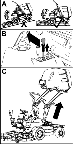
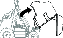
Raising the Hopper
-
Park the machine on a level surface.
-
Pull the lock collar on the hopper lift lever up and move the lever rearward to raise the hopper (Figure 23).
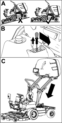
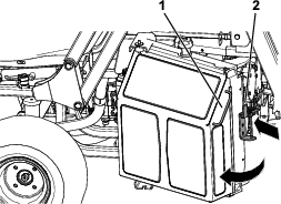
Lowering the Hopper
-
Park the machine on a level surface.
-
Pull the lock collar on the hopper lift lever up and move the lever fully forward to lower the hopper (Figure 24).
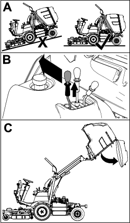
Dumping the Hopper
-
Park the machine on a level surface.
-
Pull the lock collar on the hopper dump lever up and move the lever rearward to dump the clippings from the hopper (Figure 25).
Note: The hopper door automatically unlatches when dumping the hopper.
Note: You can dump the hopper at any height.
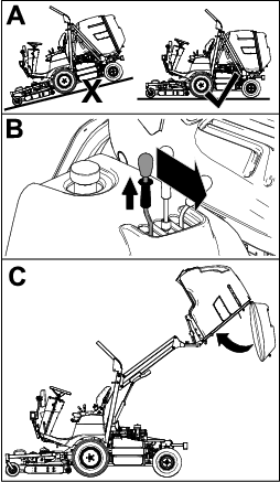
Closing the Hopper
-
Park the machine on a level surface.
-
After dumping, pull the lock collar on the hopper dump lever up and move the lever forward to close the hopper (Figure 26).
Note: The hopper door automatically latches when closing the hopper.
Clearing the Grass Chute
-
Park the machine on a level surface.
-
Disengage the PTO, lower the mower deck, and engage the parking brake.
-
Raise the hopper and secure it; refer to Raising the Hopper and Securing the Hopper in the Raised Position.
-
Shut off the engine and remove the key.
-
Tilt the seat forward.
-
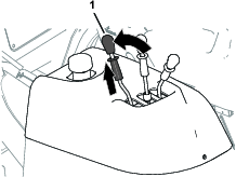
Unlatch the grass chute (Figure 27).
-
Using the handle on the chute, remove the chute and clear it and the mower deck opening (Figure 27).
-
Install the chute and secure it with the latches (Figure 27).
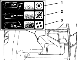
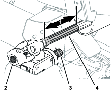
Adjusting the Hopper Sensor
If the hopper sensor activates and the PTO automatically disengages when the hopper is not full or if the chute clogs before the sensor activates, you need to adjust the sensor position.
Adjust the sensor as follows:
-
Open the hopper door.
-
Adjust the hopper sensor based on the following:
-
For normal grass and weather conditions, rotate the sensor to the mid-point position (Figure 28).
-
For wet, dense grass conditions, when picking up leaves, or if the hopper fills before the sensor activates, rotate the sensor downward (Figure 28).
-
For dry, sparse grass conditions, or if the mower deck disengages before the hopper fills, rotate the sensor upward (Figure 28).
-
Adjusting the Height of Cut
You can adjust the height of cut continually from 20 to 110 mm (3/4 to 4-1/4 inches) by using the height-of-cut switch.
Push the height-of-cut switch (Figure 8) forward to lower the height of cut. Push the height-of-cut switch rearward to increase the height of cut.
Read the height of cut indicator on the height-of-cut gauge to ensure that it is set at the desired height.
Monitor the height-of-cut gauge as you mow and adjust the height of cut if needed.
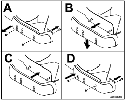
Adjusting the Skids
Mount the skids in the lower position when operating at heights of cut greater than 51 mm (2 inches) and in a higher position when operating at heights of cut lower than 51 mm (2 inches).
Adjust the skids as shown in Figure 29.
Adjusting the Front Anti-Scalp Roller
Mount the roller in the lower position when operating at heights of cut greater than 51 mm (2 inches) and in a higher position when operating at heights of cut lower than 51 mm (2 inches).
-
Park the machine on a level surface.
-
Disengage the PTO, lower the mower deck, and engage the parking brake.
-
Shut off the engine and remove the key.
-
Remove the roller shaft, bolt, and nut securing the roller to the deck bracket (Figure 30).
-
Align the roller with the appropriate holes and install the shaft with the bolt and nut (Figure 31).
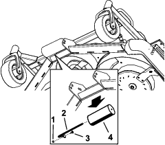
Adjusting the Rear Anti-Scalp Rollers
Mount the rollers so that there is a 19 mm (3/4 inch) clearance from the ground.
-
Park the machine on a level surface.
-
Disengage the PTO, lower the mower deck, and engage the parking brake.
-
Shut off the engine and remove the key.
-
Remove the lock pin from the roller pin (Figure 32).
-
Move the roller pin up or down to the desired position and secure it with the lock pin (Figure 32).
-
Repeat steps 4 and 5 on the other side and ensure that it matches the other setting.
Resetting the PTO Function
Note: If you leave the operator’s seat while the PTO switch is in the ON position, the machine will automatically shut off the engine.
Perform the following to reset the PTO function:
-
Push in the PTO switch knob.
-
Rotate the key to the OFF position.
-
Rotate the key to the ON/PREHEAT position, then start the engine.
-
Pull out the PTO switch knob.
Operating Tips
-
Practice driving before operating the machine, because it has a hydrostatic transmission and its characteristics are different than some turf-maintenance machines.
-
To maintain enough power for the machine and deck while mowing, regulate the traction pedal to keep the engine speed (rpm) high and constant. Decrease the ground speed as the load on the cutting blades increases; increase the ground speed as the load on the blades decreases. This allows the engine, working with the transmission, to sense the proper ground speed while maintaining a high blade-tip speed necessary for good quality of cut. Therefore, allow the traction pedal to move upward as the engine speed decreases, and press pedal slowly as the speed increases. When driving from 1 work area to another (with no load and the deck raised), have throttle in the FAST position and press the traction pedal slowly but fully to attain the maximum ground speed.
-
Before shutting off the engine, move all controls to the NEUTRAL position and move the throttle to the SLOW position. Rotate the key switch to the OFF position to shut off the engine.
-
The engine does not run when the engine coolant is in over-temperature condition. Let the engine and cooling system cool, and check the cooling system; refer to Checking the Cooling System and Coolant Level.
-
It is important to carry socket wrench with a 100 mm extension and 17 mm socket while operating the machine. Use the socket wrench to open the bypass valve if you need to push or tow the machine.
After Operation
General Safety
-
Shut off the engine, remove the key, and wait for all movement to stop before you leave the operator’s position, Allow the machine to cool before adjusting, servicing, cleaning, or storing it.
-
Clean grass and debris from the cutting units, mufflers, and engine compartment to help prevent fires. Clean up oil or fuel spills.
-
If the cutting units are in the transport position, use the positive mechanical lock (if available) before you leave the machine unattended.
-
Allow the engine to cool before storing the machine in any enclosure.
-
Remove the key and shut off the fuel (if equipped) before storing or hauling the machine.
-
Never store the machine or fuel container where there is an open flame, spark, or pilot light, such as on a water heater or on other appliances.
-
Maintain and clean the seat belt(s) as necessary
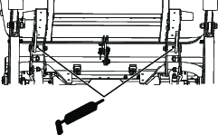
Pushing or Towing the Machine
Operator provided tool: a socket wrench with a 17 mm socket and 100 mm extension.
In case of an emergency, you can tow the machine a very short distance. However, Toro does not recommend this as standard procedure.
Important: Pushing or towing the machine faster than 3 to 5 km/h (2 to 3 mph) may damage the transmission. If you must move the machine a long distance, transport it on a truck or trailer. Whenever you push or tow the machine, open the bypass valve.
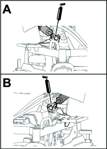
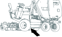
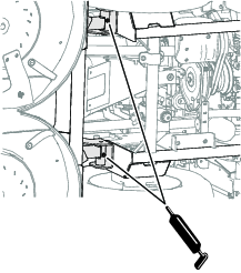
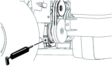
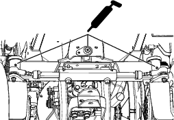
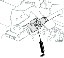
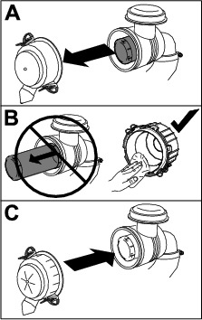
Opening the Bypass Valve on the Hydraulic Pump to Push or Tow the Machine
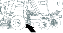
Closing the Bypass Valve on the Hydraulic Pump to Operate the Machine
Hauling the Machine
-
Use care when loading or unloading the machine into a trailer or a truck.
-
Use full-width ramps for loading the machine into a trailer or a truck.
-
Before tying down machine, lower the deck completely.
-
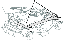
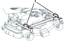
Bind the machine securely to the transport vehicle using straps, chains, cable, or ropes. Align both front and rear straps down and outward from the machine.
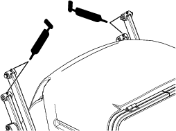
Binding the Front of the Machine
Binding the Back of the Machine
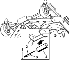
Machines without Rear Anchor Hoops
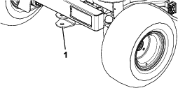
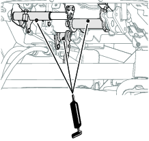
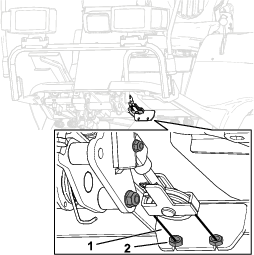
Insert a bolt or drawbar pin into the hitch and use it as the rear tie-down point (Figure 36).
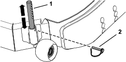
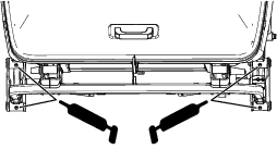
Binding the Back of the Machine
Machines with Rear Anchor Hoops
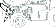
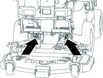
Secure the back of the machine at the 2 anchor hoops at the rear bumper (Figure 37).
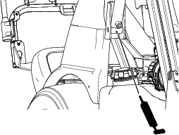
Jacking Up the Front, Right and Front, Left Sides of the Machine
-
Rotate the radiator or fuel tank out; refer to Accessing the Engine from the Right side or Accessing the Engine from the Left Side.
-
Place a jack under the frame tube (Figure 38 and Figure 39), directly under the ROPS tube, or as close as possible.
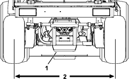
Jacking Up the Rear of the Machine
Jack up the rear, left or rear, right side of the machine using the jacking points shown in Figure 40.
Maintenance
Note: Download a free copy of the electrical or hydraulic schematic by visiting www.Toro.com and searching for your machine from the MANUALS link on the home page.
Important: Refer to your engine owner's manual for additional maintenance procedures.
Caution
If you leave the key in the switch, someone could accidently start the engine and seriously injure you or other bystanders.
Remove the key from the switch before you perform any maintenance.
Recommended Maintenance Schedule(s)
| Maintenance Service Interval | Maintenance Procedure |
|---|---|
| After the first hour |
|
| After the first 10 hours |
|
| After the first 50 hours |
|
| After the first 500 hours |
|
| Before each use or daily |
|
| Every 25 hours |
|
| Every 50 hours |
|
| Every 100 hours |
|
| Every 200 hours |
|
| Every 250 hours |
|
| Every 300 hours |
|
| Every 400 hours |
|
| Every 500 hours |
|
| Every 1,000 hours |
|
| Every 1,500 hours |
|
Pre-Maintenance Procedures
Maintenance Safety
-
Before you leave the operator’s position, do the following:
-
Park the machine on a level surface.
-
Disengage the power takeoff and lower the attachments.
-
Engage the parking brake.
-
Shut off the engine and remove the key.
-
Wait for all movement to stop.
-
-
Allow machine components to cool before performing maintenance.
-
If the cutting units are in the transport position, use the positive mechanical lock (if equipped) before you leave the machine unattended.
-
If possible, do not perform maintenance while the engine is running. Keep away from moving parts.
-
Support the machine with jack stands whenever you work under the machine.
-
Carefully release pressure from components with stored energy.
-
Keep all parts of the machine in good working condition and all hardware tightened, especially blade-attachment hardware.
-
Replace all worn or damaged decals.
-
To ensure safe, optimal performance of the machine, use only genuine Toro replacement parts. Replacement parts made by other manufacturers could be dangerous, and such use could void the product warranty.
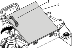
Securing the Hopper in the Raised Position
-
Park the machine on a level surface.
-
Raise the hopper to the fully raised position; refer to Raising the Hopper.
-
Secure the hopper by performing the following:
-
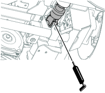
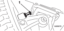
Push the pin on magnetic safety lock inward (Figure 41).
-
While still holding the pin in, lower magnetic safety lock onto the hydraulic cylinder (Figure 41).
-
Repeat steps 1 and 2 on the other side.
-
Lubrication
Greasing the Mower Deck
| Maintenance Service Interval | Maintenance Procedure |
|---|---|
| Every 50 hours |
|
Grease specification: No. 2 lithium grease
Important: Dusty and dirty operating conditions could cause dirt to get into the bearings and bushings, resulting in accelerated wear.
Note: Lubricate the grease fittings immediately after every washing, regardless of interval specified.
-
Remove the belt cover; refer to Removing the Belt Cover.
-
Wipe grease fitting clean so debris is not forced into the bearing or bushing.
-
Pump grease into the bearing or bushing.
-
Wipe off excess grease.
-
Install the belt cover; refer to Installing the Belt Cover.
Greasing the Bearings and Bushings
| Maintenance Service Interval | Maintenance Procedure |
|---|---|
| Every 50 hours |
|
Grease specification: No. 2 lithium grease
Important: Dusty and dirty operating conditions could cause dirt to get into the bearings and bushings, resulting in accelerated wear.
Note: Lubricate the grease fittings immediately after every washing, regardless of interval specified.
-
Wipe grease fitting clean so debris is not forced into the bearing or bushing.
-
Pump grease into the bearing or bushing.
-
Wipe off excess grease.
The bearing and bushing lubrication points are as follows:
-
Brake and traction pedal pivot bushings (Figure 43)
-
Rod fittings for the deck-lift cylinders (Figure 44).
-
Deck lift arm pivot points (Figure 45)
-
PTO idler-pulley bracket (Figure 46)
-
Hopper arms—upper (Figure 47)
-
Hopper arms—lower, front (Figure 48)
-
Hopper arms—lower, rear (Figure 49)
-
Hopper pivots under the hopper (Figure 50)
-
Steering pivot points (Figure 51)
Lubricating the Driveshaft U-Joints
| Maintenance Service Interval | Maintenance Procedure |
|---|---|
| Every 200 hours |
|
Grease specification: No. 2 lithium grease
Important: Dusty and dirty operating conditions could cause dirt to get into the bearings and bushings, resulting in accelerated wear.
Note: Lubricate the grease fittings immediately after every washing, regardless of interval specified.
-
Wipe grease fitting clean so debris is not forced into the bearing or bushing.
-
Pump grease into the bearing or bushing.
-
Wipe off excess grease.
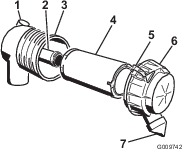
Lubricating the Driveshaft Sliding Joints
| Maintenance Service Interval | Maintenance Procedure |
|---|---|
| Every 100 hours |
|
Lubrication specification: anti-sieze compound
-
Disconnect the driveshaft from the mower-deck gearbox; refer to Disconnecting the Driveshaft from the Mower-Deck Gearbox.
-
Pull the front half of the driveshaft (Figure 54) forward about 25 cm (10 inches).
-
Wipe clean the splines of the gearbox shaft and the splines of the driveshaft (Figure 54).
-
Wipe clean the sliding surface of the forward driveshaft (Figure 54).
-
Apply anti-sieze compound to the splines of the gearbox shaft and U-joint coupling (Figure 54).
-
Apply anti-sieze to the sliding surface of the forward driveshaft (Figure 54).
-
Move the front half of the driveshaft rearward to align the U-joint coupling with the gearbox shaft.
-
Wipe off excess anti-sieze compound from the driveshaft.
-
Connecting the driveshaft to the mower-deck gearbox; refer to Connecting the Driveshaft to the Mower-Deck Gearbox.
Engine Maintenance
Engine Safety
-
Shut off the engine and remove the key before checking the oil or adding oil to the crankcase.
-
Do not change the governor speed or overspeed the engine.
Accessing the Engine
Manually Rotating the Hopper
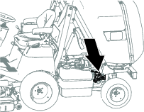
Accessing the Engine from the Engine-Access Cover
-
Raise the hopper to the fully raised position and secure it with the magnetic safety locks; refer to Raising the Hopper and Securing the Hopper in the Raised Position.
-
Using the handle on the engine-access cover, raise the cover to access the engine (Figure 57).
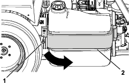
Accessing the Engine from the Right side
Accessing the Engine from the Left Side
Remove bolt from the left side of the fuel-tank bracket and rotate the fuel tank to the right to access the engine (Figure 59).
Note: To rotate the fuel tank out fully, rotate the steering wheel to the right to the fully locked position.
Servicing the Air Cleaner
| Maintenance Service Interval | Maintenance Procedure |
|---|---|
| Every 100 hours |
|
Note: Replace the air cleaner more frequently (every few hours) if operating conditions are extremely dusty or sandy.
Cleaning the Air-Cleaner Cover
| Maintenance Service Interval | Maintenance Procedure |
|---|---|
| Every 50 hours |
|
Note: Do not use compressed air to clean the cover or air filter(s).
Check the air-cleaner body for damage which could cause an air leak. Replace a damaged air-cleaner body.
Clean the air-cleaner cover as shown in Figure 60.
Servicing the Air-Cleaner Filters
| Maintenance Service Interval | Maintenance Procedure |
|---|---|
| Every 100 hours |
|
-
Gently slide the primary filter out of the air-cleaner body (Figure 61).
Note: Avoid knocking the filter into the side of the body.
Important: Do not attempt to clean the primary filter.
-
Remove the safety filter (if equipped).
Note: Remove the safety filter only if you intend to replace it.
Important: Never attempt to clean the safety filter. If the safety filter is dirty, then the primary filter is damaged, and you should replace both filters.
-
Inspect the new filter(s) for damage by looking into the filter while shining a bright light on the outside of the filter.
Note: Holes in the filter appear as bright spots. Inspect the element for tears, an oily film, or damage to the rubber seal. If the filter is damaged, do not use it.
-
If you are replacing the safety filter, carefully slide the new filter into the filter body (Figure 61).
Important: To prevent engine damage, always operate the engine with both air filters and cover installed.
-
Carefully slide the new primary filter over the safety filter and ensure that it is fully seated by pushing on the outer rim of the filter while installing it.
Important: Do not press on the soft inside area of the filter.
-
Install the air-cleaner cover with the side indicated as “UP” facing upward and secure the latches (Figure 61).
Servicing the Engine Oil
The engine ships with oil in the crankcase.
Crankcase capacity: approximately 3.4 L (3.6 US qt) with the filter.
Engine oil specification:
-
Engine oil-type—API Classification Level Required: CH-4, CI-4 or higher.
-
Engine oil viscosity
-
Preferred oil: SAE 15W-40 (above 0°F)
-
Alternate oil: SAE 10W-30 or 5W-30 (all temperatures)
-
Note: Toro Premium Engine Oil is available from your authorized Toro distributor in either 15W-40 or 10W-30 viscosity. See the parts catalog for part numbers.
Checking the Engine-Oil Level
| Maintenance Service Interval | Maintenance Procedure |
|---|---|
| Before each use or daily |
|
Note: The best time to check the engine oil is when the engine is cool before it has been started for the day. If you have already run the engine, allow the oil to drain back down to the sump for at least 10 minutes before checking. If the oil level is at or below the low mark on the dipstick, add oil to bring the oil level to the high mark. Do not overfill. If the oil level is between the high and low marks, you do not need to add oil.
Check the engine-oil level as shown in Figure 62.
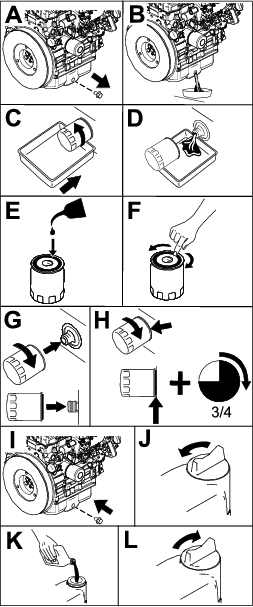
Changing the Engine Oil and Filter
| Maintenance Service Interval | Maintenance Procedure |
|---|---|
| After the first 50 hours |
|
| Every 250 hours |
|
Note: Change the engine oil and filter more frequently when the operating conditions are extremely dusty or sandy.
-
Start the engine and let it run 5 minutes to allow the oil to warm up.
-
Park the machine on a level surface.
-
Disengage the PTO, lower the mower deck, and engage the parking brake.
-
Raise and secure the hopper, and open the engine-access cover; refer to Accessing the Engine from the Engine-Access Cover.
-
Shut off the engine and remove the key.
-
Change the engine oil and engine-oil filter as shown in Figure 63.
Note: Tighten the filter until the oil-filter gasket touches the engine, and then turn it an extra 3/4 turn.
Fuel System Maintenance
Note: Refer to Adding Fuel for proper the fuel recommendations.
Danger
Under certain conditions, diesel fuel and fuel vapors are highly flammable and explosive. A fire or explosion from fuel can burn you and others and can cause property damage.
Never smoke when handling fuel, and stay away from an open flame or where a spark may ignite fuel fumes.
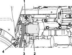
Priming the Fuel System
At the left side of the engine, operate the lever of the fuel pump until you fill the fuel-filter bowl (Figure 64).
Bleeding the Fuel-Injection Pump
-
Park the machine on a level surface.
-
Engage the parking brake.
-
Ensure that the fuel tank is at least half full.
-
Unlatch the radiator; refer to Accessing the Engine from the Right side.
-
Place a drain pan under the air-bleed screw.
-
Open the air-bleed screw on the fuel-injection pump (Figure 65).
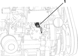
-
Operate the lever of the fuel pump until you see solid stream of fuel flows out around the screw; refer to Figure 64 in Priming the Fuel System.
-
Tighten the air-bleed screw (Figure 65).
Note: The engine should start after you perform this procedure. However, if the engine does not start, air may be trapped between the injection pump and the injectors. Contact your authorized Toro distributor.
-
Wipe clean any fuel that has accumulated around the injection pump.
Draining Water from the Fuel/Water Separator
| Maintenance Service Interval | Maintenance Procedure |
|---|---|
| Every 50 hours |
|
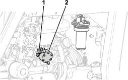
Checking for Water in the Fuel Bowl
-
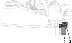
Look at the water indicator in the fuel-filter bowl to determine if the float is elevated by water in the fuel-filter bowl (Figure 66).
-
If there is water in the fuel-filter bowl, rotate the fuel shutoff valve for the fuel/water separator to the CLOSED position (Figure 67) and perform the steps in Draining Water from the Fuel Bowl.
Draining Water from the Fuel Bowl
-
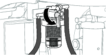
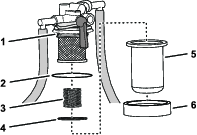
Place a drain pan under the fuel-filter bowl, remove the bowl nut, and remove the filter bowl from the filter head (Figure 68).
Note: You will remove the spring and the float when you remove the filter bowl.
-
Empty the filter bowl of fuel and water.
-
At the filter head, check the condition of the O-ring (Figure 68).
Note: Replace the O-ring if it is worn or damaged.
-
Lubricate the O-ring with clean fuel.
-
Assemble the spring and float into the fuel-filter bowl (Figure 68).
-
Assemble the filter bowl and bowl nut onto the filter head and tighten the nut by hand (Figure 68).
-
Open the fuel shutoff valve and if needed prime the fuel system; refer to Priming the Fuel System.
-
Check the fuel/water separator for leaks.
Note: Repair all fuel leaks before operating the machine.
Replacing the Filter of the Fuel/Water Separator
| Maintenance Service Interval | Maintenance Procedure |
|---|---|
| Every 500 hours |
|
Removing the Filter Element
-
Clean the area around the fuel-filter head (Figure 69).
-
Rotate the fuel shutoff valve for the fuel/water separator to the CLOSED position (Figure 70).
-
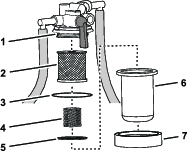
Place a drain pan under the fuel-filter bowl, remove the bowl nut, and remove the filter bowl from the filter head (Figure 71).
Note: You will remove the spring and the float when you remove the filter bowl.
-
Drain the filter bowl of fuel and clean the filter-head-mounting surface.
Installing the Filter Element
-
Lubricate the O-ring with clean fuel.
-
Assemble the filter element onto the filter head; refer to Figure 71 in Removing the Filter Element.
-
Assemble the spring and float into the fuel-filter bowl; refer to Figure 71) in Removing the Filter Element
-
Assemble the filter bowl and bowl nut onto the filter head and tighten the nut by hand; refer to Figure 71 in Removing the Filter Element.
-
Open the fuel shutoff valve and if needed prime the fuel system; refer to Priming the Fuel System.
-
Check the fuel/water separator for leaks.
Note: Repair all fuel leaks before operating the machine.
Replacing the Fuel-Filter Element
Toward the Front, Right Side
| Maintenance Service Interval | Maintenance Procedure |
|---|---|
| Every 500 hours |
|
-
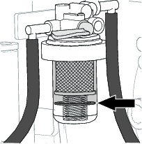
Clean the area around the fuel-filter head (Figure 72).
-
Remove the filter and clean the filter-head-mounting surface (Figure 72).
-
Lubricate the filter gasket with clean fuel.
-
Assemble the filter element onto the filter head.
-
Assemble the filter bowl and bowl nut onto the filter head and tighten the nut by hand
-
Prime the fuel system; refer to Priming the Fuel System.
-
Check the fuel/water separator for leaks.
Note: Repair all fuel leaks before operating the machine.
Cleaning the Fuel Tank
| Maintenance Service Interval | Maintenance Procedure |
|---|---|
| Every 400 hours |
|
Inspecting the Fuel Lines and Connections
| Maintenance Service Interval | Maintenance Procedure |
|---|---|
| Every 400 hours |
|
Inspect the fuel lines for deterioration, damage, or loose connections.
Electrical System Maintenance
Electrical System Safety
-
Disconnect the battery before repairing the machine. Disconnect the negative terminal first and the positive last. Connect the positive terminal first and the negative last.
-
Charge the battery in an open, well-ventilated area, away from sparks and flames. Unplug the charger before connecting or disconnecting the battery. Wear protective clothing and use insulated tools.
Accessing the Battery
-
Park the machine on a level surface.
-
Disengage the PTO, lower the mower deck, and engage the parking brake.
-
Shut off the engine and remove the key.
-
Remove the 3 socket-head screws from the left console (Figure 74).
-
Remove the throttle-lever knob (Figure 74).
-
Lift the left console up and set it aside (Figure 74).
Servicing the Battery
| Maintenance Service Interval | Maintenance Procedure |
|---|---|
| Every 25 hours |
|
Important: Before welding on the machine, disconnect the negative cable from the battery to prevent damage to the electrical system.
Removing the Battery
Warning
Battery terminals or metal tools could short against metal machine components causing sparks. Sparks can cause the battery gasses to explode, resulting in personal injury.
-
When removing or installing the battery, do not allow the battery terminals to touch any metal parts of the machine.
-
Do not allow metal tools to short between the battery terminals and metal parts of the machine.
Warning
Incorrect battery cable routing could damage the machine and cables causing sparks. Sparks can cause the battery gasses to explode, resulting in personal injury.
-
Always disconnect the negative (black) battery cable before disconnecting the positive (red) cable.
-
Always connect the positive (red) battery cable before connecting the negative (black) cable.
-
Park the machine on a level surface.
-
Disengage the PTO, lower the mower deck, and engage the parking brake.
-
Shut off the engine and remove the key.
-
Access the battery; refer to Accessing the Battery.
-
Remove the battery as shown in Figure 75.
Installing the Battery
Install the battery as shown in Figure 76.
Charging the Battery
Warning
Charging the battery produces gasses that can explode.
Never smoke near the battery and keep sparks and flames away from the battery.
Important: Always keep the battery fully charged (1.265 specific gravity). This is especially important to prevent battery damage when the temperature is below 0°C (32°F).
-
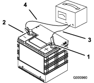
Charge battery for 10 to 15 minutes at 25 to 30 A or 30 minutes at 10 A.
-
When the battery is fully charged, unplug the charger from the electrical outlet, then disconnect the charger leads from the battery posts (Figure 77).
-
Install the battery in the machine and connect the battery cables; refer to Installing the Battery.
Note: Do not run the machine with the battery disconnected, electrical damage may occur.
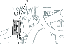
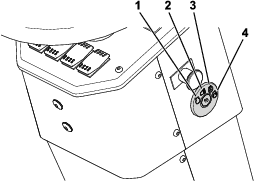
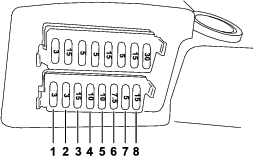
Servicing the Fuses
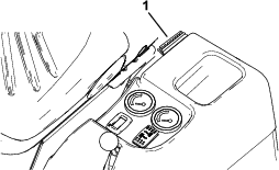
The electrical system is protected by fuses. It requires no maintenance, however, if a fuse blows check the component/circuit for a malfunction or short.
The fuse block and fuses are located to the left of the operator’s seat (Figure 78).
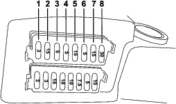
Use the following table when replacing a fuse:
| Circuit | Fuse Type |
| Security | 3 A |
| PTO | 15 A |
| Electronic control unit and buzzer | 5 A |
| Differential lock | 5 A |
| Mower deck valve and operator’s seat | 15 A |
| Alternator and dashboard | 5 A |
| Work lights, brake lights, full-beam lights, and light control unit | 15 A |
| Pull and hazard light switch, spark plugs, and key switch | 30 A |
| Circuit | Fuse Type |
| Right steady light and plate light | 3 A |
| Left steady light | 3 A |
| Full-beam light | 15 A |
| Headlight | 10 A |
| Warning device | 10 A |
| Indicator lights | 7.5 A |
| Rotating beacon light | 5 A |
| Hazard-light switch | 15 A |
There are also 2 fuses (40 A) that protect the main machine wire harness (Figure 81).
Servicing the Wiring Harness
Prevent corrosion of wiring terminals by applying Grafo 112X (Skin-over) grease, Toro Part No. 505-47, to the inside of all harness connectors whenever you replace the harness.
Important: Whenever working with the electrical system, always disconnect the battery cables, negative (-) cable first, to prevent wiring damage from short-outs.
Drive System Maintenance
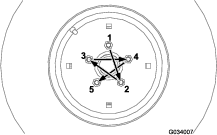
Torquing the Wheel Lug Nuts
| Maintenance Service Interval | Maintenance Procedure |
|---|---|
| After the first hour |
|
| After the first 10 hours |
|
| Every 200 hours |
|
Wheel lug nut torque specification: 85 to 90 N∙m (62 to 66 ft-lb)
Torque the lug nuts at the front and rear wheels in a crossing pattern as shown in Figure 82 to the specified torque.
Maintaining the Rear Wheel Alignment
Checking the Rear Wheel Alignment
| Maintenance Service Interval | Maintenance Procedure |
|---|---|
| Every 200 hours |
|
-
Park the machine on a level surface.
-
Disengage the PTO, lower the mower deck, and engage the parking brake.
-
Shut off the engine and remove the key.
-
Rotate the steering wheel so that the rear wheels are straight ahead.
-
Measure the center-to-center distance at wheel hub height, in front and in back of the rear tires.
Note: The rear wheels should not toe-in or toe-out when they are aligned correctly.
-
If the wheels toe-in or toe-out, align the wheels; refer to Adjusting the Rear Wheel Toe-In.
Adjusting the Rear Wheel Toe-In
-
Loosen the jam nuts at both ends of the left and right tie rods.
-
Adjust both tie rods until center-to-center distance at front and back of rear wheels is the same (Figure 83).
-
When rear wheels are adjusted correctly, tighten jam nuts against tie rods.
Adjusting Steering Stops
The rear-axle-steering stops help prevent over-travel of the steering cylinder in case of impact on the rear wheels. Adjust the stops so that there is 0.23 cm (0.090 inch) clearance between the bolt head and the knuckle on the axle when you turn the steering wheel completely to the left or to the right.
Thread the bolts in or out until you attain a clearance of 0.23 cm (0.090 inch); refer to Figure 84.
Cooling System Maintenance
Cooling System Safety
-
Swallowing engine coolant can cause poisoning; keep out of reach from children and pets.
-
Discharge of hot, pressurized coolant or touching a hot radiator and surrounding parts can cause severe burns.
-
Always allow the engine to cool at least 15 minutes before removing the radiator cap.
-
Use a rag when opening the radiator cap, and open the cap slowly to allow steam to escape.
-
-
Do not operate the machine without the covers in place.
-
Keep your fingers, hands and clothing clear of rotating fan and drive belt.
Coolant Specification
Cooling system capacity: 7.5 L (8 US qt)
Coolant-type specification:
| Recommended Coolant |
|
Note: Coolant must meet or exceed ASTM Standard 3306 |
| Glycol based pre-diluted coolant (50/50 blend) |
| or |
| Glycol based coolant mixed with distilled water (50/50 blend) |
| or |
| Glycol based coolant mixed with good quality water (50/50 blend) |
| CaCO3 + MgCO3 <170 ppm |
| Chloride <40 ppm (CI) |
| Sulfur <100 ppm (SO4) |
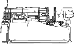
Checking the Cooling System and Coolant Level
| Maintenance Service Interval | Maintenance Procedure |
|---|---|
| Before each use or daily |
|
Warning
If the engine has been running, the radiator will be pressurized and the coolant inside will be hot. If you remove the cap, coolant may spray out, causing severe burns.
-
Do not remove the recovery-tank cap to check coolant levels. Instead, look at the level from the side of the tank.
-
Do not remove the recovery-tank cap when the engine is hot. Allow the engine to cool for at least 15 minutes or until the radiator cap is cool enough to touch without burning your hand.
-
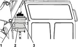
Check the level of the coolant in the expansion tank (Figure 85).
-
If the coolant is low, remove the expansion-tank cap and add the recommended replacement coolant as required.
Do not use water only or alcohol-based coolants.Do not overfill.
-
Install the expansion-tank cap.
Checking the Radiator Screen and Radiator for Debris
| Maintenance Service Interval | Maintenance Procedure |
|---|---|
| Before each use or daily |
|
To prevent the engine from overheating, keep the radiator screen and radiator clean. Check the radiator screen and radiator for buildup of grass, dust, and debris, and if necessary, clean any debris off these parts.
Cleaning the Radiator Screen and Radiator
| Maintenance Service Interval | Maintenance Procedure |
|---|---|
| Every 200 hours |
|
| Every 1,500 hours |
|
Note: If the PTO shuts off due to high engine temperature, first check the radiator screen and radiator for an excessive buildup of debris. Clean the system before operating the machine. Do not shut off the engine immediately; allow the engine to cool by running it without a load.
Clean the radiator as follows:
-
Remove the radiator screen.
-
Working from the fan side of the radiator, blow with low pressure, 172 kPa (25 psi), compressed air (do not use water). Repeat this step from the front of the radiator and again from the fan side.
-
After you have thoroughly cleaned the radiator, clean out any debris that may have collected in the channel at the radiator base.
-
Clean the radiator screen and install it onto the machine.
Brake Maintenance
Adjusting the Service Brakes
| Maintenance Service Interval | Maintenance Procedure |
|---|---|
| After the first 10 hours |
|
| After the first 50 hours |
|
After adjusting the service brakes after the first 50 hours of operation, you may need to adjust the brakes again after considerable use.
You should measure a gap approximately a 13 mm (1/2 inch) between the brake pedal to the front end of the slot when the brake pedal is pressed down fully.
-
Push the brake pedal down to check if there is a sufficient gap in the front end of the slot (Figure 86).
-
Release the brake pedal.
-
If an adjustment is necessary, loosen the front and rear jam nuts on each side of the brake cables (Figure 87).
-
Push the brake pedal down and move the brake cables forward or rearward.
-
Tighten the jam nuts to lock the cable positions.
-
Repeat steps 3 through 5 until you set the brake pedal to the desired position.
Belt Maintenance
Checking the Condition of the Alternator Belt
| Maintenance Service Interval | Maintenance Procedure |
|---|---|
| Every 200 hours |
|
Check alternator belt for wear or damage.
Note: Replace the alternator belt if you find it worn or damaged.
Tensioning the Alternator Belt
| Maintenance Service Interval | Maintenance Procedure |
|---|---|
| After the first 10 hours |
|
| Every 200 hours |
|
-
Park the machine on a level surface.
-
Disengage the PTO, lower the mower deck, and engage the parking brake.
-
Shut off the engine and remove the key.
-
Access the engine from the left side; refer to Accessing the Engine from the Left Side.
-
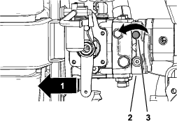
Loosen the alternator pivot bolt and lock bolt (Figure 88).
-
Tension the alternator belt until you achieve 10 mm (3/8 inch) belt deflection midway between the pulleys with a force of 4.5 kg (10 lb).
-
Tighten the alternator lock bolt (Figure 88).
-
Tighten the alternator pivot bolt (Figure 88).
Servicing the PTO Belts
Checking the PTO Belt Tension
| Maintenance Service Interval | Maintenance Procedure |
|---|---|
| After the first 10 hours |
|
| After the first 50 hours |
|
| Every 200 hours |
|
-
Park the machine on a level surface.
-
Disengage the PTO, lower the mower deck, and engage the parking brake.
-
Shut off the engine and remove the key.
-
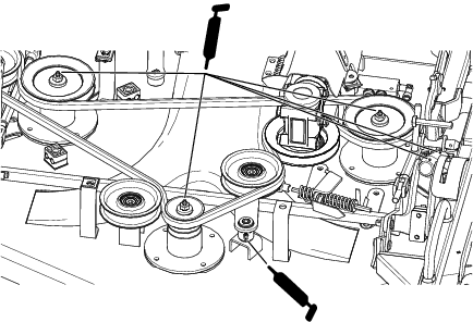
Look at the tension-indicator arrow of the idler-pulley tensioner.
The outer surface of the washer should align with the tension-indicator arrow
-
If needed, rotate the nut for the idler-pulley tensioner until the tension-indicator arrow aligns with the outer surface of the washer (Figure 89).
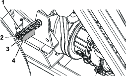
Replacing the PTO Belts
Important: Replace the PTO belts as a matched set.
Removing the PTO Belts
-
Park the machine on a level surface.
-
Disengage the PTO, lower the mower deck, and engage the parking brake.
-
Shut off the engine and remove the key.
-
Access the left and right sides of the engine; refer to Accessing the Engine from the Left Side and Accessing the Engine from the Right side.
-
At the radiator side, unhook the clutch-damper spring from the spring bracket (Figure 90).
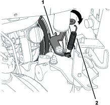
-
Remove the 2 bolts and 2 nuts that secure the anti-rotation tube to the right engine mount (Figure 91).
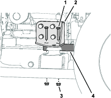
-
Move the anti-rotation tube rearward and remove it from the machine (Figure 92).
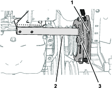
-
Loosen the nut for the idler-pulley tensioner; refer to Figure 89 in Checking the PTO Belt Tension.
-
Rotate the idler pulley toward the engine and remove the belts from the machine (Figure 93).
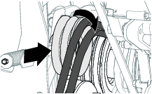
Installing the PTO Belts
-
Align the be PTO belts over the pulleys (Figure 94).
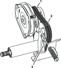
-
Align the pin of the anti-rotation tube with the hole in the PTO-clutch plate; refer to Figure 92 in Removing the PTO Belts.
-
Secure the anti-rotation tube to the right engine mount with the 2 bolts and 2 nuts that you removed in step 6 of Removing the PTO Belts.
-
Hook the clutch-damper spring between the inboard clutch-plate bolt and the spring bracket; refer to Figure 90 in Removing the PTO Belts.
-
Tighten the nut for the idler-pulley tensioner; refer to Checking the PTO Belt Tension.
-
Close the radiator to the machine; refer to Accessing the Engine from the Right side.
-
Swing the fuel tank in to the chassis and secure the fuel tank; refer to Accessing the Engine from the Left Side.
Controls System Maintenance
Adjusting the PTO Clutch Gap
| Maintenance Service Interval | Maintenance Procedure |
|---|---|
| Every 200 hours |
|
-
Park the machine on a level surface.
-
Disengage the PTO, lower the mower deck, and engage the parking brake.
-
Raise and secure the hopper; refer to Raising the Hopper and Securing the Hopper in the Raised Position.
-
Shut off the engine and remove the key.
-
Open the engine-access cover; refer to Accessing the Engine from the Engine-Access Cover.
-
Adjust the air gap so that a 0.4 mm (0.015 inch) feeler gauge slides in between the clutch lining and friction plate with light pressure (Figure 95).
Note: You can decrease the gap by turning the adjusting nut clockwise (Figure 95). The maximum service gap is 0.7 mm (0.030 inch). Adjust all 3 air gaps.
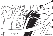
-
After you have set all 3 gaps, check the 3 gaps again.
Note: Adjusting 1 gap can alter the other gaps.
Adjusting the Traction Pedal
Adjusting the Traction-Pedal Stop
You can adjust the traction pedal for operator comfort or to reduce or increase the maximum forward speed of the machine.
You can also adjust the traction pedal to reduce or increase the maximum reverse speed of the machine.
-
Move the traction pedal fully forward (Figure 96).
For maximum speed, there should be a 3 mm (1/8 inch) gap between the traction pedal and the traction-pedal stop.
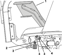
-
If you want to reduce the forward speed of the machine, perform the following:
-
Using a wrench, hold the forward traction-pedal stop and loosen the jam nut on the back side of the bracket (Figure 96).
-
Move the traction pedal to the desired position (Figure 96).
-
Adjust the jam nut on the back of the bracket until traction-pedal stop contacts the traction pedal (Figure 96).
Note: Shortening the traction-pedal stop position will increase the forward speed of the machine.
-
While holding the traction-pedal stop, torque the jam nut at the front of the bracket to 37 to 45 N∙m (27 to 33 ft-lb).
-
Adjusting the Traction Rod
If more adjustment is required, adjust the traction rod (Figure 97) as follows:
-
Park the machine on a level surface.
-
Disengage the PTO, lower the mower deck, and engage the parking brake.
-
Shut off the engine and remove the key.
-
Remove the bolt and nut securing traction rod end to the pedal.
-
Loosen the jam nut securing rod end to the traction rod (Figure 97).
-
Rotate the rod until you achieve the desired length.
-
Tighten the jam nut (Figure 97) and secure the rod end to the traction pedal with the bolt and nut removed to lock the angle of the foot pedal.
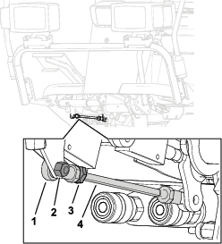
Hydraulic System Maintenance
Hydraulic System Safety
-
Seek immediate medical attention if fluid is injected into skin. Injected fluid must be surgically removed within a few hours by a doctor.
-
Ensure that all hydraulic-fluid hoses and lines are in good condition and all hydraulic connections and fittings are tight before applying pressure to the hydraulic system.
-
Keep your body and hands away from pinhole leaks or nozzles that eject high-pressure hydraulic fluid.
-
Use cardboard or paper to find hydraulic leaks.
-
Safely relieve all pressure in the hydraulic system before performing any work on the hydraulic system.
Hydraulic Fluid Specification
The hydraulic-fluid reservoir is filled at the factory with high-quality hydraulic fluid. Check the level of the hydraulic fluid before you start the engine for the first time and daily thereafter.
Use Toro Premium All-Season Hydraulic Fluid (Available in 5-gallon pails or 55-gallon drums. See the Parts Catalog or Toro distributor for part numbers.)
If the Toro fluid is not available, you may use other fluids provided that they meet all the following material properties and industry specifications. Consult with your lubricant distributor to identify a satisfactory product.
Note: Toro does not assume responsibility for damage caused by improper substitutions, so use only products from reputable manufacturers who will stand behind their recommendation.
| Material Properties: | ||
| Viscosity, ASTM D445 | St @ 40°C 42 to 50 | |
| St @ 100°C 7.6 to 8.5 | ||
| Viscosity Index ASTM D2270 | 140 or higher | |
| Pour Point, ASTM D97 | -40°F to -49°F | |
| FZG, Fail stage | 11 or better | |
| Water content (new fluid) | 500 ppm (maximum) | |
| Industry Specifications: | Vickers I-286-S (Quality Level), Vickers M-2950-S (Quality Level), Denison HF-0 | |
Important: The ISO VG 46 multigrade fluid offers optimal performance in a wide range of temperature conditions. For operation in consistently high ambient temperatures, 65°F (18°C) to 120°F (49°C), ISO VG 68 hydraulic fluid may offer improved performance.
Important: Many hydraulic fluids are almost colorless, making it difficult to spot leaks. A red dye additive for the hydraulic-system oil is available in 20ml (2/3 fl oz) bottles. 1 bottle is sufficient for 15 to 22 L (4 to 6 US gallons) of hydraulic oil. Order Toro Part No. 44-2500 from your authorized Toro distributor.
Servicing the Hydraulic System
Preparing to Service the Hydraulic System
-
Park the machine on a level surface.
-
Disengage the PTO, lower the mower deck, and engage the parking brake.
-
Place all controls in the NEUTRAL position and start the engine.
-
Run the engine at lowest possible engine speed to purge the system of air.
Important: Do not run the PTO.
-
Cycle the steering wheel several times fully to the left and right, and align the steering wheels straight forward.
Checking the Hydraulic-Fluid Level
| Maintenance Service Interval | Maintenance Procedure |
|---|---|
| Before each use or daily |
|
-
Park the machine on a level surface.
-
Ensure that the hopper is fully lowered and level and the mower deck is lowered.
-
Disengage the PTO, engage the parking brake, shut off the engine, and remove the key.
-
Remove the dipstick from hydraulic tank and wipe the dipstick with a clean cloth (Figure 98).
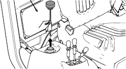
-
Insert the dipstick into the fill tube and thread the dipstick cap onto the tube.
-
Remove the dipstick and check the fluid level (Figure 99).
The hydraulic fluid level is normal when the fluid is indicated between the 2 marks in the dipstick.
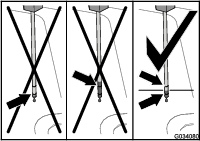
-
If the fluid level is below the lower mark in the dipstick, add the specified hydraulic fluid into the fill tube (Figure 100) until you can see that the fluid level is between the 2 marks the dipstick.
Important: Do not fill the hydraulic tank with hydraulic fluid above the upper mark in the dipstick.
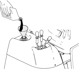
-
Thread the dipstick fill cap onto the filler tube.
Note: Do not tighten the cap with a wrench.
-
Check all hoses and fittings for leaks.
Changing the Hydraulic Fluid and Filter
| Maintenance Service Interval | Maintenance Procedure |
|---|---|
| After the first 500 hours |
|
| Every 200 hours |
|
| Every 1,000 hours |
|
Hydraulic-reservoir capacity: approximately 5.0 L (5.3 US qt)
-
Park the machine on a level surface.
-
Ensure that the hopper is fully lowered and level and the mower deck is raised.
-
Disengage the PTO, engage the parking brake, shut off the engine, and remove the key.
-
Use a siphon pump to empty the hydraulic tank (Figure 101).
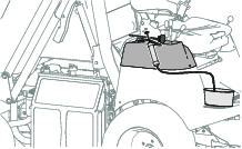
-
Rotate the radiator to access the filter; refer to Accessing the Engine from the Right side
-
Replace the hydraulic filter as shown in Figure 102.
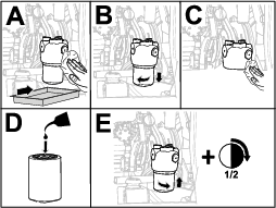
-
Add the specified hydraulic fluid into the fill tube until you can see that the fluid level is between the 2 marks the dipstick (Figure 99).
Important: Do not fill the hydraulic tank with hydraulic fluid above the upper mark in the dipstick.
-
Start the engine, cycle the steering wheel and deck-lift cylinders, and check for fluid leaks. Allow the engine to run for about 5 minutes, then shut it off.
-
After 2 minutes, check the level of the hydraulic fluid; refer to Checking the Hydraulic-Fluid Level.
Mower Deck Maintenance
Rotating the Mower Deck into the Maintenance Position
-
Park the machine on a level surface.
-
Disengage the PTO, lower the mower deck, and engage the parking brake.
-
Raise the hopper and engage the magnetic safety locks; refer to Securing the Hopper in the Raised Position.
-
Unlatch and remove the grass chute; refer to Clearing the Grass Chute.
-
Pull and rotate the rear link pins on both sides of the mower deck.
-
Raise the mower deck.
-
Shut off the engine and remove the key.
-
Using the handle and foot peg on the left side of the mower deck, rotate the front of the mower deck upward to the maintenance position.
Rotating the Mower Deck into the Mowing Position
Important: Ensure that you remove the grass chute before performing this procedure; otherwise, damage may occur.
-
Park the machine on a level surface.
-
Lower the mower deck.
-
Rotate the rear link pins to release them into the rear links.
-
Insert the grass chute, rotate the operator’s seat, and lower the hopper.
Servicing the Blades
To ensure a superior quality of cut, keep the blades sharp. For convenient sharpening and replacement, you may want to keep extra blades on hand.
Replace the blades if they hit a solid object, they are out of balance, or a they are bent. To ensure best performance and continued safety conformance of the machine, use genuine Toro replacement blades. Replacement blades made by other manufacturers may not meet the safety standards.
Blade Safety
-
Inspect the blade periodically for wear or damage.
-
Use care when checking the blades. Wrap the blades or wear gloves, and use caution when servicing the blades. Only replace or sharpen the blades; never straighten or weld them.
-
On multi-bladed machines, take care as rotating 1 blade can cause other blades to rotate.
Before Inspecting or Servicing the Blades
Prepare the mower deck for maintenance; refer to Safety.
Inspecting the Blades
| Maintenance Service Interval | Maintenance Procedure |
|---|---|
| Before each use or daily |
|
-
Inspect the cutting edges (Figure 103).
-
If the edges are not sharp or have nicks, remove and sharpen the blade; refer to Sharpening and Balancing the Blades.
-
Inspect the blades, especially in the sail area.
-
If you notice any cracks, wear, or a slot forming in this area, immediately install a new blade (Figure 103).
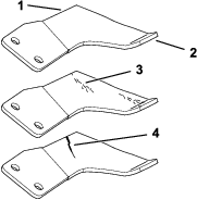
Removing the Blades
Removing the Center Blade
-
Hold the blade end using a cloth or a thickly padded glove.
-
Remove the blade bolt, serrated washer, blade retainer, curved washer, and blade from the spindle shaft (Figure 104).
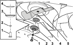
Removing the Wing Blade Assembly
The right and left blade assemblies rotate in opposite directions and are unique to their positions. Ensure that you install the fan discs and blades in the correct positions.
-
Hold the wing blade assembly using a cloth or a thickly padded glove.
-
Remove the blade bolt, serrated washer, blade retainer, and curved washer from the spindle shaft (Figure 105).
-
Remove the blade assembly (Figure 105).
Important: The right blade assembly blade bolt has a left-handed thread. Turn the blade bolt clockwise to loosen it.
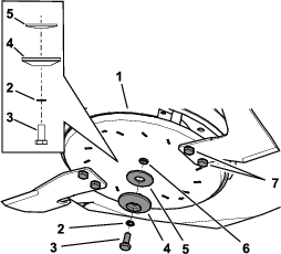
Sharpening and Balancing the Blades
Sharpening and Balancing the Center Blade
-
Use a file or sharpening tool to sharpen the cutting edge at both ends of the blade (Figure 106).
Note: Maintain the original angle–22°.
Note: The blade keeps its balance if you remove the same amount of material from both cutting edges.
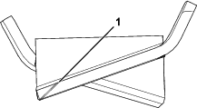
-
Check the balance of the blade by putting it on a blade balancer (Figure 107).
Note: If the blade stays in a horizontal position, the blade balances and it is ready for use.
Note: If the blade is not balanced, file some metal off the heavy end of the blade in the sail area only (Figure 106).
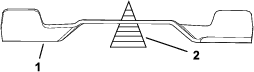
-
Repeat this procedure until the blade balances.
Sharpening and Balancing the Wing Blades
-
Use a file or sharpening tool to sharpen the cutting edge at both ends of the blade assembly (Figure 108).
Note: Maintain the original angle–22°.
Note: The blade keeps its balance if you remove the same amount of material from both cutting edges.
-
Check the balance of the blade assembly by putting it on a blade balancer (Figure 109).
Note: If the blade assembly stays in a horizontal position, the blade assembly balances and it is ready for use.
Note: If the blade assembly is not balanced, file some metal off the heavy end of the blade in the sail area only (Figure 108).

-
Repeat this procedure until the blade assembly balances.
Installing the Blades
Installing the Center Blade
-
Hold the blade end using a cloth or a thickly padded glove.
-
Install the blade using the previously removed blade bolt, serrated washer, blade retainer, and curved washer (Figure 110).
Important: The sail area of the blade must be pointing upward toward the inside of the mower to ensure proper cutting.
Note: Install the cupped side of the curved washer towards the blade.
-
Torque the blade bolt to 53 N∙m (39 ft-lb).
Installing the Wing Blade Assembly
Important: The right blade assembly blade bolt has a left-handed thread. Ensure that you turn the blade bolt in the proper direction; otherwise, you could cause damage.
-
Hold the wing blade assembly using a cloth or a thickly padded glove.
-
Install the wing blade assembly using the previously removed disc bolt, serrated washer, blade retainer, and curved washer (Figure 111).
Important: The sail area of the blades must be pointing upward toward the inside of the mower to ensure proper cutting.
Note: Install the cupped side of the curved washer towards the blade.
-
Torque the disc bolt to 53 N∙m (39 ft-lb).
-
Torque the blade bolts to 50 N∙m (37 ft-lb).
Disconnecting the Driveshaft from the Mower-Deck Gearbox
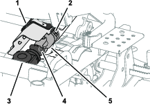
Connecting the Driveshaft to the Mower-Deck Gearbox
-
Align the splines of the driveshaft-universal joint with the splines in the gearbox coupling; refer to Figure 112 in Disconnecting the Driveshaft from the Mower-Deck Gearbox.
-
Press the spring-loaded pin and then push the end of the driveshaft forward; refer to Figure 112 in Disconnecting the Driveshaft from the Mower-Deck Gearbox.
-
Release the spring-loaded pin and check that the universal joint of the driveshaft is locked into the mower-deck gearbox; refer to Figure 112 in Disconnecting the Driveshaft from the Mower-Deck Gearbox.
-
Close the universal-joint cover and secure it to the belt cover with the quarter-turn fastener; refer to Figure 112 in Disconnecting the Driveshaft from the Mower-Deck Gearbox.
Removing the Mower Deck
-
Park the machine on a level surface.
-
Disengage the PTO and engage the parking brake.
-
Before lowering the deck, pull and rotate the rear link pins at both sides of the mower deck (Figure 113).
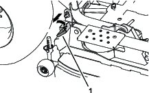
-
Disconnect the hydraulic hoses from each side of the traction unit (Figure 114).
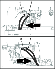
-
Lower the mower deck and tilt the hopper back.
-
Shut off the engine and remove the key.
-
Tilt the seat forward.
-
Remove the grass chute; refer to Clearing the Grass Chute.
-
Disconnect the universal joint of the driveshaft from the mower-deck gearbox; refer to Disconnecting the Driveshaft from the Mower-Deck Gearbox.
-
Remove the 2 lynch pins and 2 clevis pins that secure the lift arms at each side of the mower deck (Figure 115).
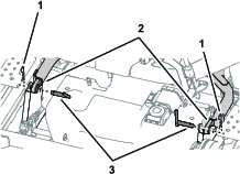
-
Roll the mower deck forward and away from the traction unit.
Installing the Mower Deck
-
Park the machine on a level surface.
-
Tilt the hopper back.
-
Shut off the engine and remove the key.
-
Remove the grass chute; refer to Clearing the Grass Chute.
-
Roll the mower deck rearward to the traction unit.
-
Install the lynch pin and clevis pin to secure the lift arms on each side; refer to Figure 115 in Removing the Mower Deck.
-
Connect the universal joint of the driveshaft from the mower-deck gearbox; refer to Connecting the Driveshaft to the Mower-Deck Gearbox.
-
Install the grass chute; refer to Clearing the Grass Chute.
-
Tilt the seat rearward.
-
Start the engine.
-
Lower the hopper.
-
Raise the mower deck until the castor wheels are slightly off the ground.
-
Rotate the rear link pins to engage the mower deck rear lift links; refer to Figure 113 in Removing the Mower Deck.
-
Connect the hydraulic hoses as follows:
-
Connect the hydraulic hose marked with a blue identifier to the inboard quick-disconnect coupler (marked with a blue identifier); refer to Figure 114 in Removing the Mower Deck.
-
Connect the hydraulic hose marked with a red identifier to the outboard quick-disconnect coupler (marked with a red identifier); refer to Figure 114 in Removing the Mower Deck.
-
Repeat steps 1 and 2 for the hydraulic hoses at the other side of the mower deck.
-
Removing the Belt Cover
Note: You must separate the U-joint of the driveshaft from the mower-deck gearbox before removing the belt cover; refer to Disconnecting the Driveshaft from the Mower-Deck Gearbox.
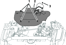
Installing the Belt Cover
-
Align the quarter-turn fasteners of the belt cover with the clip nuts of the mower deck; refer to Figure 116 in Removing the Belt Cover.
-
Rotate the quarter-turn fasteners clockwise.
-
Install the bolt in the belt cover to the nut clip of the mower deck; refer to Figure 116 in Removing the Belt Cover.
Removing the Pulley Cover
-
Remove the belt cover; refer to Removing the Belt Cover.
-
Remove the bolt and washer that secure the pulley cover to the mower deck (Figure 117).
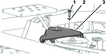
-
Remove the pulley cover from the machine.
Installing the Pulley Cover
-
Align the pulley cover over the right-most pulley; refer to Figure 117 in Removing the Pulley Cover.
-
Secure the pulley cover to the clip nut of the deck with the bolt and washer that you remove in step 2 in Removing the Pulley Cover.
Changing the Oil in the Mower-Deck Gearbox
| Maintenance Service Interval | Maintenance Procedure |
|---|---|
| After the first 50 hours |
|
| Every 300 hours |
|
Gearbox oil specification: PG2 and API GL4, GL5, or MT1
Gearbox oil viscosity: LSX 75W90
Gearbox oil capacity: 112 ml (3.8 oz)
Preparing to Change the Gearbox Oil
-
Park the machine on a level surface, disengage the PTO, and lower the mower deck.
-
Engage the parking brake, shut off the engine, and remove the key.
-
Remove the belt cover; refer to Removing the Belt Cover
Removing the Gearbox
-
Loosen the mower-belt tensioner and remove the mower belt from the gearbox pulley; refer to step 4Removing the Mower Belt
-
Remove the 4 bolts that secure the mower-deck gearbox to the gearbox support (Figure 118).
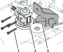
Changing the Gearbox Oil
-
Remove the case plug from the case-plug hole of the mower-deck gearbox (Figure 119).
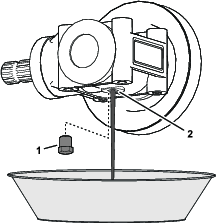
-
Position the gearbox over drain pan and drain the oil from the gearbox completely (Figure 119).
-
Rotate the gearbox to align the case-plug hole up (Figure 120).
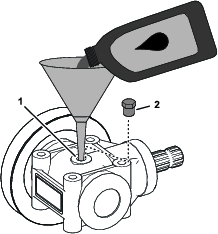
-
Add 112 ml (3.8 oz) of the specified gearbox oil into the case of the gearbox through the case-plug hole (Figure 120).
-
Install the case plug into the case-plug hole of the mower-deck gearbox (Figure 120).
Installing the Gearbox
-
Align the holes in the mower-deck gearbox with the holes in the gearbox support; refer to Figure 118 in Removing the Gearbox.
-
Secure the gearbox to the support with the 4 bolts that you removed in step 2 of Removing the Gearbox.
-
Install and tension the mower belt; refer to steps 1 and 2 in Installing the Mower Belt.
-
Install the belt cover; refer to Installing the Belt Cover.
-
Connect the driveshaft to the mower-deck gearbox; refer to Connecting the Driveshaft to the Mower-Deck Gearbox.
Leveling the Mower Deck
Preparing to Level the Deck
-
Park the machine on a flat level surface.
-
Lower the mower deck and set the deck-lift lever to the float position.
-
Check bent or damaged mower blades or wing-blade disks, refer to Inspecting the Blades.
Note: Replace bent or damaged blades and disks before leveling the deck.
Leveling the Mower Deck Left to Right
-
Adjust the height of cut to the 75 mm (3 inches) position (Figure 121).
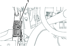
-
Shut off the engine and remove the key.
-
Align a wing blade to the outermost position (Figure 122).
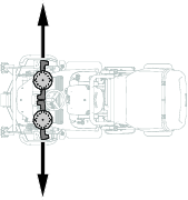
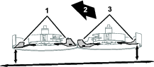
-
Measure the distance between the ground and the outermost point of the cutting edge of the blade with a gauge block (Figure 122).
Record your measurement here: -
Align the wing blade at the other side of the mower deck to the outermost position (Figure 122).
-
Measure the distance between the ground and the outermost point of the blade cutting edge with a gauge block (Figure 122).
Record your measurement here: -
If the difference between the measurements is greater than 3.2 mm (1/8 inch), perform the following:
-
Loosen the 2 nuts securing the leveling link (Figure 123).
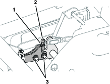
-
Loosen the jam nut that secures the socket-head bolt (Figure 123).
-
Adjust the wing blade height for the right side of the deck as follows:
-
Rotate the socket-head bolt clockwise to lower the right side of the mower deck.
-
Turn the socket-head bolt counterclockwise to raise the right side of the mower deck.
-
-
-
Measure the outermost point of the blade cutting edges (Figure 122).
-
Repeat steps 7 and 8 until the difference between the measurements is 3.2 mm (1/8 inch) or less.
-
Tighten the 2 nuts for the leveling link and the jam nut for the socket-head bolt (Figure 123).
Leveling the Mower Deck Front to Back
-
Adjust the height of cut to the 75 mm (3 inches) position (Figure 124).
-
Shut off the engine and remove the key.
-
Align a wing blade to the forward-most position (Figure 125).
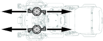
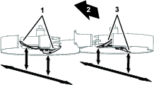
-
Measure the distance between the ground and the forward-most point of the blade cutting edge with a gauge block (Figure 126).
Record the left blade measurement here: Record the right blade measurement here: 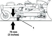
-
Measure the distance between the ground and the rear-most point of the blade cutting edge with a gauge block (Figure 127).
Record the left blade measurement here: Record the right blade measurement here: 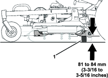
-
If the difference between the measurements is less the 4.8 mm (3/16 inch) or greater than 8 mm (5/16 inch), perform the following:
-
Remove the belt cover; refer to Removing the Belt Cover.
-
Loosen the jam nuts for the deck-tilt adjusters (Figure 128 and Figure 129) at each side of the deck.
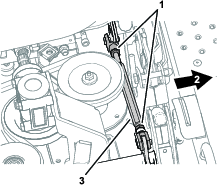
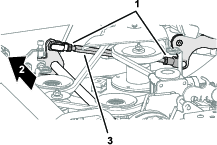
-
Rotate the deck-tilt adjusters until the rear-most point of the blade cutting edge is 4.8 to 8 mm (3/16 to 5/16 inch) higher than the front-most point of the blade cutting edge.
-
Repeat step 3 for the blade at the other side of the machine.
Important: Ensure that the rear-most points of the left and right blade-cutting edges measure within 3.2 mm (1/8 inch) of each other.
-
-
Tighten the jam nuts for the deck-tilt adjusters (Figure 123).
-
Check the deck for left to right level; refer to Leveling the Mower Deck Left to Right.
-
Install the belt cover; refer to Installing the Belt Cover.
Adjusting the Height-of-Cut Pointer
-
With the mower blades aligned front to back and the front of the blades adjusted to 75 mm (3 inches) from the ground, check the position of the height-of-cut indicator.
-
Sit in the operator’s seat and look at the pointer of the height-of-cut indicator (Figure 130).
-
If the pointer of the height-of-cut indicator is not aligned to 75 mm mark, perform the following:
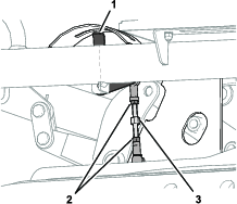
Checking the Mower Deck Belt Tension
| Maintenance Service Interval | Maintenance Procedure |
|---|---|
| After the first 50 hours |
|
| Every 50 hours |
|
-
Park the machine on a level surface.
-
Disengage the PTO, lower the mower deck, and engage the parking brake.
-
Shut off the engine and remove the key.
-
Loosen or tighten the jam nut until the tension indicator arrow aligns with the outer surface of the washer (Figure 132).
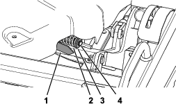
Replacing the Mower Deck Belt
Removing the Mower Belt
-
Park the machine on a level surface, disengage the PTO, and lower the mower deck.
-
Engage the parking brake, shut off the engine, and remove the key.
-
Remove the belt cover and pulley cover; refer to Removing the Belt Cover and Removing the Pulley Cover.
-
Loosen the jam nut of the belt tensioner until you can slip the belt off the belt-tensioning pulley (Figure 133).
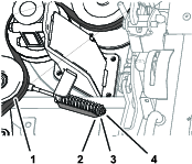
-
Remove the belt from the pulleys of the mower deck.
Installing the Mower Belt
-
Route the new belt around the pulleys as shown in Figure 134.
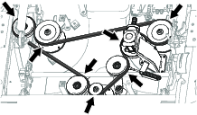
-
Tighten the jam nut until the tension indicator arrow aligns with the outer surface of the washer (Figure 133).
-
Install the pulley cover; refer to Installing the Pulley Cover.
-
Install the belt cover; refer to Installing the Belt Cover.
Switching the Skids
When the skids wear out, you can switch them to the other side of the mower deck to gain additional use.
-
Park the machine on a level surface.
-
Disengage the PTO and engage the parking brake.
-
Rotate the mower deck to the maintenance position; refer to Rotating the Mower Deck into the Maintenance Position.
-
Shut off the engine and remove the key.
-
Remove the skids from the sides of the mower deck (Figure 135).
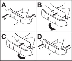
-
Switch the skids and install them using the previously removed screws (Figure 135).
Important: Use only the top 2 sets of holes when you install the skids.
Maintaining the Hopper
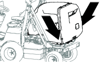
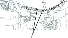
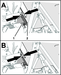
Cleaning
Note: Improper wash-down procedures may negatively affect bearing life. Do not wash down the machine when it is still hot and avoid directing high-pressure or high-volume spray at the bearings.
Cleaning Under the Mower Deck Belt Cover
| Maintenance Service Interval | Maintenance Procedure |
|---|---|
| Before each use or daily |
|
-
Disengage the blade-control switch (PTO) and engage the parking brake.
-
Shut off the engine, remove the key, and wait for all moving parts to stop before leaving the operating position.
-
Insert an air nozzle in the gap between the belt cover and the top of the mower deck. Use compressed air to clear any accumulated grass from under the mower deck belt cover.
Cleaning Under the Mower Deck
| Maintenance Service Interval | Maintenance Procedure |
|---|---|
| Before each use or daily |
|
-
Disengage the blade-control switch (PTO) and engage the parking brake.
-
Shut off the engine, remove the key, and wait for all moving parts to stop before leaving the operating position.
-
Prepare the mower deck for maintenance; refer to Rotating the Mower Deck into the Maintenance Position.
-
Remove any packed grass or debris, and clean as necessary.
Cleaning the Hopper Screen
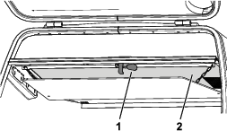
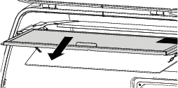
Cleaning the Rear Slots in the Hopper Door
| Maintenance Service Interval | Maintenance Procedure |
|---|---|
| Before each use or daily |
|
-
Disengage the blade-control switch (PTO) and engage the parking brake.
-
Raise the hopper (Figure 140) to the full height position; refer to Raising the Hopper.
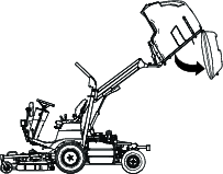
-
Dump the hopper (Figure 140) and leave it in the full dumped position, with the rear door hanging freely; refer to Dumping the Hopper.
Note: The hopper door automatically unlatches when dumping the hopper.
-
Shut off the engine, remove the key, and wait for all moving parts to stop before leaving the operating position.
-
Secure the raised hopper with the safety locks; refer to Figure 41 in Securing the Hopper in the Raised Position.
-
Using compressed air, clear the grass and debris from the slots in the bottom of the internal metal plate of the hopper door. (Figure 141).
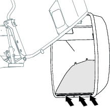
-
Secure the safety locks to their stowed position; refer to Figure 41 in Securing the Hopper in the Raised Position.
-
Rotate the hopper to the level position.
-
Lower the hopper; refer to Lowering the Hopper.
Disposing of Waste
Engine oil, batteries, hydraulic fluid, and engine coolant are pollutants to the environment. Dispose of these according to your state and local regulations.
Storage
Storage Safety
-
Shut off the engine, remove the key, and wait for all movement to stop before you leave the operator’s position. Allow the machine to cool before adjusting, servicing, cleaning, or storing it.
-
Do not store the machine or fuel container where there is an open flame, spark, or pilot light, such as on a water heater or other appliance.
Storing the Battery
-
Service the battery and cables as follows:
-
Remove the battery terminals from the battery posts; refer to Removing the Battery.
-
Clean the battery, terminals, and posts with a wire brush and baking-soda solution.
-
Coat the cable terminals and battery posts with Grafo 112X skin-over grease (Toro Part No. 505-47) or petroleum jelly to prevent corrosion.
-
If you plan to store the machine more than 30 days, remove the battery and charge it fully.
Note: Slowly charge the battery for 24 hours every 60 days to prevent lead sulfation of the battery.
-
-
Store the battery in position on the machine.
-
Leave the cables disconnected if the battery is stored in the machine.
-
Store the battery in a cool atmosphere to avoid quick deterioration of the charge in the battery.
-
To prevent the battery from freezing, ensure that it is fully charged. The specific gravity of the electrolyte in a fully charged battery is between 1.265 to 1.299.
Preparing the Machine
Important: Do not use brackish or reclaimed water to clean the machine.
-
Thoroughly clean the machine, mower deck, and the engine, paying special attention to these areas:
-
Radiator and radiator screen
-
Underneath the deck
-
Under the deck belt covers
-
PTO shaft assembly
-
All grease fittings and pivot points
-
Remove the steering column rear access panel and clean out inside
-
Beneath the seat plate and top of the transmission
-
-
Check and adjust the air pressure in the tires; refer to Checking the Air Pressure in the Tires
-
Remove, sharpen, and balance the mower blades; refer to the Operator’s Manual for your mower deck.
-
Check for loose fasteners and tighten them as necessary.
-
Lubricate all grease fittings and apply oil to pivot points and the transmission bypass-valve pins. Wipe clean any excess lubricant.
-
Lightly sand and use touch-up paint on scratched or chipped paint, or rust. Repair any dents in the metal body.
Preparing the Engine
-
Change the engine oil and oil filter; refer to Changing the Engine Oil and Filter.
-
Start the engine and run it at idle speed for 2 minutes.
-
Shut off the engine.
-
Empty the fuel from the fuel tank, fuel lines, pump, filter, and separator.
-
Flush the fuel tank with clean diesel fuel and connect all fuel lines.
-
Thoroughly clean and service the air-cleaner assembly; refer to Servicing the Air-Cleaner Filters.
-
Seal the air-cleaner inlet and the exhaust outlet with weatherproof masking tape.
-
Secure all fuel-system fittings.
-
Check the anti-freeze protection level of the cooling system and adjust the concentration of the coolant as needed for the coldest expected temperature in your area.
-
Check the oil-filler cap and fuel-tank cap to ensure that they are secure.
Troubleshooting
| Problem | Possible Cause | Corrective Action |
|---|---|---|
| The key switch is in the On position, but the dash panel indicator lights do not turn on. |
|
|
| The dash panel indicator lights turn on with the key switch in the On position, but the starter motor does not turn. |
|
|
| The engine starts only intermittently or the engine runs irregularly. |
|
|
| The starter motor turns, but the engine does not start. |
|
|
| The engine shuts off while the PTO is still engaged. |
|
|
| The cut is uneven and collection system is insufficient. |
|
|
| The machine vibrates while operating. |
|
|
| The engine-oil warning light illuminates. |
|
|
| The mower deck does not run when the PTO switch is engaged. |
|
|