|
|
|
|
 |
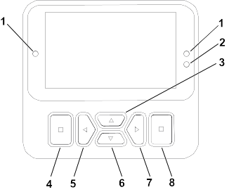
Menu
|
 |
Tank is empty (less than 10% volume)
|
|
|
|
Scroll up/down
|
 |
Tank volume is low (10% to 29%)
|
|
|
|
Scroll left/right
|
 |
Tank volume is half full (30% to 69%)
|
|
 |
Previous screen
|
 |
Tank volume is full (70% to 100%)
|
|
 |
Decrease value
|
 |
Increase the tank volume by 1 gallon
|
|
 |
Increase value
|
 |
Increase the tank volume by 10 gallons
|
|
 |
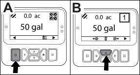
Accept
|
 |
Increase the tank volume by 25 Liters
|
|
 |
Save
|
 |
Boom is off
|
|
 |
PIN passcode
|
 |
Boom is active
|
|
 |
Exit (faults)menu
|
 |
Clear all areas
|
|
 |
Battery voltage
|
 |
Clear active area
|
|
 |
The parking brake is on.
|
 |
Areas sprayed
|
|
 |
Sit in the seat.
|
|
All areas screen
|
|
 |
Hour meter
|
  |
Navigate to a sprayer area
|
|
 |
Locked
|
|||
 |
Brake lock
|
 |
Throttle lock
|
|
 |
Speed lock
|
 Protected under Protected Menus—accessible only by entering PIN
|
Menu Item
|
Description
|
|---|---|
|
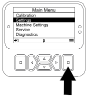
Calibration
|
The Calibration menu assists in calibration of the flow meter and speed sensor; refer to your Multi Pro Operator’s Manual.
|
|
Settings
|
The Settings menu allows you to customize and modify the display configuration variables.
|
|
Machine Settings
|
The Machine Settings menu allows you to configure machine variables.
|
|
Service
|
The Service menu contains information on the machine such as hours of use and machine faults.
|
|
Diagnostics
|
The Diagnostics menu displays the state of each machine switch, sensor, and control output. You can use this to troubleshoot
certain issues as it quickly tells you which machine controls are on and which are off.
|
|
About
|
The About menu lists the model number, serial number, and software version of your machine.
|
|
Menu Item
|
Description
|
|---|---|
|
Test Speed
|
Sets the test speed for calibration.
|
|
Flow Cal
|
Calibrates the flow meter.
|
|
Speed Cal
|
Calibrates the speed sensor.
|
|
Use Flow Cal Default
|
Resets the flow calibration to the default calculated average, not the actual volume.
|
|
Use Speed Cal Default
|
Resets the speed calibration to the default calculated average, not the actual speed.
|
|
Menu Item
|
Description
|
|---|---|
|
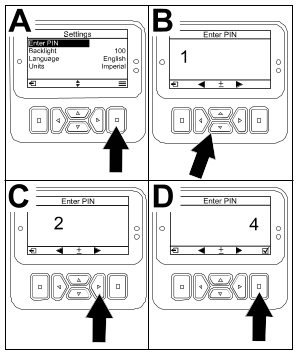
Enter PIN
|
Allows a person (superintendent/mechanic) authorized by your company with the PIN code to access protected menus.
|
|
Backlight
|
Controls the brightness of the LCD display.
|
|
Language
|
Controls the language used on the display*.
|
|
Units
|
Controls the units used on the display (Imperial, Turf, or Metric).
|
|
Protected Menus
|
Grants access to protected menus.
|
|
Protect Settings
|
Allows the ability to change the settings in the protected settings.
|
|
Menu Item
|
Description
|
|---|---|
|
Tank Alert
|
Sets the low tank volume alert.
|
|
Hill Assist
|
Enables or disables the hill assist feature.
|
|
Geolink
|
Satellite navigation option
|
|
Left Boom
|
Adjusts the width of the left section.
|
|
Center Boom
|
Adjusts the width of the center section.
|
|
Right Boom
|
Adjusts the width of the right section.
|
|
Reset Defaults
|
Resets the default values.
|
|
Menu Item
|
Description
|
|---|---|
|
Faults
|
The Faults menu contains a list of the recent machine faults. Refer to the Service Manual or contact your authorized Toro distributor for more information on the Faults menu and the information contained there.
|
|
Hours
|
Lists the total number of hours that the machine, engine and PTO have been on, as well as the number of hours the machine
has been transported and service due.
|
|
Flow Rate
|
Displays the current flow rate.
|
|
Flow Cal Value
|
Displays the current multiplier used to calculate the difference between the assumed flow and the calibrated flow.
|
|
Speed Cal Value
|
Displays the current multiplier used to calculate the difference between the assumed speed and the calibrated speed.
|
|
Menu Item
|
Description
|
|---|---|
|
Pumps
|
Accesses the pump inputs, momentary rinse, and time rinse options.
|
|
Booms
|
Accesses the boom inputs and outputs.
|
|
Throttle Lock
|
Accesses the throttle lock inputs and outputs.
|
|
Engine Run
|
Accesses the engine run inputs and outputs.
|
|
Menu Item
|
Description
|
|---|---|
|
Model
|
Lists the model number of the machine.
|
|
SN
|
Lists the serial number of the machine.
|
|
S/W Revision
|
Lists the software revision of the primary controller.
|
|
InfoCenter S/W Revision
|
Lists the software revision of the InfoCenter.
|
|
ICAN Bus
|
Lists the CAN Bus
|
 .
. until the correct first digit appears, then press the right navigation button
 to move on to the next digit. Repeat this step until the last digit is entered.
 .
. (Off).
 (On), set the PIN code, and turn the key in the ignition switch to the Off position and then to the On position.
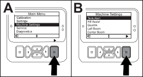
|
Setting
|
Default Value
|
|
Test Speed
|
0.0
|
|
Hill Assist
|
enabled
|
|
Spray Tank Alert
|
1 gal/ltr
|
|
L Boom
|
80 in
|
|
C Boom
|
60 in
|
|
R Boom
|
80 in
|
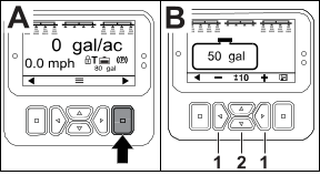 button to navigate to the right.
 to jump to ±10 (for US units) or ±25 (for metric units).
 to change the volume by 1 increment.
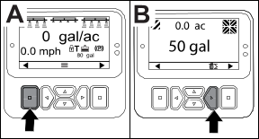
|
200
|
Start Prevented—Pump switch active
|
|
201
|
Start Prevented—Not in Neutral
|
|
202
|
Start Prevented—Out of seat
|
|
203
|
Start Prevented—Throttle pedal is not home
|
|
204
|
Start Prevented—Starter engage timeout
|
|
205
|
Parking brake is engaged
|
|
206
|
Pump Start Prevented—Boom active
|
|
207
|
Pump Start Prevented—Engine rpm high
|
|
208
|
Throttle/Speed Lock Prevented—Pump is not active
|
|
209
|
Throttle Lock Prevented—Parking brake is not engaged
|
|
210
|
Speed Lock Prevented—Operator not in seat or parking brake in engaged
|
|
211
|
Throttle/Speed Lock Prevented—Clutch or service brake is engaged
|
|
212
|
Tank low volume alert
|
|
213
|
Rinse pump is On
|
|
220
|
Flow sensor calibration
|
|
221
|
Flow sensor calibration—Fill water in tank and enter volume filled
|
|
222
|
Flow sensor calibration—Turn on the pump
|
|
223
|
Flow sensor calibration—Turn on all of the booms
|
|
224
|
Flow sensor calibration—Calibration commenced
|
|
225
|
Flow sensor calibration—Calibration complete
|
|
226
|
Flow sensor calibration—Exiting calibration mode
|
|
231
|
Speed sensor calibration
|
|
232
|
Speed sensor calibration—Fill the fresh water tank, press next
|
|
233
|
Speed sensor calibration—Fill the sprayer half full with water, press next
|
|
234
|
Speed sensor calibration—Enter the calibration distance, press next
|
|
235
|
Speed sensor calibration—Mark and drive the entered distance with sprayer sections off
|
|
236
|
Speed sensor calibration—Speed sensor calibration in progress
|
|
237
|
Speed sensor calibration—Speed sensor calibration complete
|
|
238
|
Speed sensor calibration—Turn off the booms
|
|
241
|
Calibration out of bounds, using default
|
|
Code
|
Description
|
|---|---|
|
1
|
TEC is faulty
|
|
2
|
One or more of the TEC output fuses (7.5 A) is faulty
|
|
3
|
Main power relay or circuit wiring is faulty
|
|
4
|
Charging system or circuit wiring is faulty
|
|
5
|
Start relay or circuit wiring is faulty
|
|
6
|
Kill relay circuit is faulty
|
|
7
|
Spray pump clutch or circuit wiring is faulty
|
|
8
|
Spray pump indicator light or circuit wiring is faulty
|
|
9
|
Throttle lock or circuit wiring is faulty
|
|
10
|
Throttle lock indicator or circuit wiring is faulty
|
|
11
|
Master boom valve actuator or circuit wiring is faulty
|
|
12
|
Rinse pump relay, optional rinse pump, or circuit wiring is faulty
|
|
13
|
Brake hold solenoid or circuit wiring is faulty
|
|
14
|
InfoCenter software is not recognized by TEC
|
|
15
|
Brake pressure switch or circuit wiring is faulty (circuit is closed even though the brake pedal has been released)
|
|
16
|
Service brake or throttle home sensor, or circuit wiring, is faulty (circuit is open even though the brake or accelerator
pedal has been released)
|
|
17
|
Starter timeout (starter has been engaged for more than 30 seconds)
|
|
Inputs
|
Outputs
|
|---|---|
|
Pump Switch
|
Main Pump
|
|
Momentary Rinse
|
Rinse Pump
|
|
Timed Rinse
|
|
|
Throttle Home
|
|
|
Timer
|
|
Inputs
|
Outputs
|
|---|---|
|
Left Boom
|
Master Boom
|
|
Center Boom
|
|
|
Right Boom
|
|
|
Master Boom
|
|
Inputs
|
Outputs
|
|---|---|
|
Key Start
|
OK Run
|
|
Key Run
|
Engine Output
|
|
Neutral
|
|
|
Seat or Parking Brake
|
|
|
Pump Off
|
|
Inputs
|
Outputs
|
|---|---|
|
Throttle/Speed Lock Switch
|
Throttle/Speed Lock
|
|
Neutral
|
|
|
Parking Brake
|
|
|
Main Pump
|
|
|
Clutch Off
|