Important: Install the windshield kits before installing this kit.

Safety

Cooling System Safety

  • Swallowing engine coolant can cause poisoning; keep out of reach from children and pets.

  • Discharge of hot, pressurized coolant or touching a hot radiator and surrounding parts can cause severe burns.

    • Always allow the engine to cool at least 15 minutes before removing the radiator cap.

    • Use a rag when opening the radiator cap, and open the cap slowly to allow steam to escape.

  • Do not operate the machine without the covers in place.

  • Keep your fingers, hands and clothing clear of rotating fan and drive belt.

  • Shut off the engine and remove the key before performing maintenance.

Safety and Instructional Decals

Graphic

Safety decals and instructions are easily visible to the operator and are located near any area of potential danger. Replace any decal that is damaged or missing.

decal145-2219

Installation

Preparing the Machine

  1. Park the machine on a level surface.

  2. Shift the transmission lever to the P (PARK) position.

  3. Shut off the engine and remove the key.

  4. Wait for the engine to cool completely.

    g364252
  5. Disconnect the negative (-) battery cable from the battery post.

    g365494
  6. Raise the hood; refer to the machine Operator’s Manual.

  7. Drain approximately 2 L (1/2 US gallon) of engine coolant (or until coolant stops flowing out of the rubber hoses) from the cooling system; refer to the Operator’s Manual.

    Note: Retain coolant for reuse after you install the kit.

Installing the HVAC Control Panel

Parts needed for this procedure:

HVAC control panel1
Rotary switch1
Rotary linear switch1
A/C rocker switch1
Switch nut (7/16 inch)2
Knob2
Button-head bolt (5/8 inch)4
Locknut (#10-24)4
Control cable1
Wire harness1
  1. On the dashboard, remove the 4 switch plugs and cut out the material between the switch cutouts (Figure 3).

    g398819

    Warning

    Using a drill without wearing eye protection may allow debris to enter the eye, causing personal injury.

    When drilling, always wear eye protection.

  2. Locate the 2 drill pilot dimples (Figure 4) and drill 2 pilot holes (5 mm or 3/16 inch) directly over the pilot dimples.

    g398820
  3. Using the HVAC control panel as a template, drill the other 2 holes located on the right side.

  4. Install the 2 switches with knobs onto the control panel with 2 switch nuts (7/16 inch) as shown in Figure 5 and Figure 6.

  5. Install the A/C rocker switch into the panel (Figure 5 and Figure 6).

  6. Install a knob over each switch (Figure 5 and Figure 6).

    g431722
    g418766
  7. Move the control knobs to the middle position as shown in Figure 7.

    g430156
  8. Ensure that the heater switch is in the middle position and connect one end of the control cable to the back of the heater switch (Figure 8).

    g409582
  9. Ensure that the water valve is in the middle position and connect it onto the other end of the control cable (Figure 9).

    g460374
  10. Ensure that the heater switch can sweep from low heat to high heat and that the water valve fully opens and closes. Adjust the cable if necessary.

  11. For the A/C rocker switch, plug the black-wire spade terminal onto the gold colored switch terminal and labeled number 3.

    Note: Refer to the numbers imprinted in the A/C rocker switch for the correct terminals (Figure 10).

  12. Plug the white-wire spade terminal onto the switch terminal labeled number 2.

  13. Plug the red-wire spade terminal onto the switch terminal labeled number 1 (Figure 10).

  14. Plug the 5-terminal connector on the kit wire-harness into the back of the airflow switch (Figure 10).

  15. Route the control cable, water valve, and wire harness through the dashboard and secure the control panel assembly onto the dashboard with 4 button-head bolts (5/8 inch) and 4 locknuts (#10-24); refer to Figure 11. Torque the bolts to 3 N∙m (30 in-lb).

    g419184
    g419185
  16. Connect the HVAC harness to the vehicle harness (Figure 12 and Figure 18).

    g418763
  17. Route the harness down the right-frame channel. Keep the harness on the interior side of the channel (Figure 13).

    g419314

Cutting Holes for the Vents

  1. Locate the 4 drill pilot dimples on the top of the dashboard (Figure 14) and drill 4 holes (76 mm or 3 inches) directly over the pilot dimples.

    Note: Use a 76 mm (3 inch) hole saw to drill the vent holes.

    g398901
  2. Locate the 2 drill pilot dimples on the floorboard (Figure 15) and drill 2 holes (76 mm or 3 inches) directly over the pilot dimples.

  3. Remove the burrs from the holes.

    g398912

Routing the Long Hoses

Parts needed for this procedure:

Suction hose1
Long discharge hose1

Note: Route the long discharge hose and suction hose before installing the HVAC box. This allows for more room to route the hoses.

  1. Route the suction hose from the front of the machine to the back near the compressor area (Figure 16 and Figure 17).

    g443239
  2. Route the discharge hose from the front of the machine to the back near the condenser area (Figure 17 and Figure 18).

    g460889
    g443114

Assembling the HVAC Box Assembly

Parts needed for this procedure:

HVAC box assembly1
Air-intake cover1
HVAC mount bracket1
Flange adapter2
Foam seal1
Carriage bolt (1/4 x 3/4 inch)6
Locknut (1/4 inch)6
Coolant hose (5/8 x 13 inches)1
Coolant hose (5/8 x 26 inches)1
Vent hose (55 mm x 68.6 cm or 27 inches)4
Vent hose (55 mm x 45.7 cm or 18 inches)2
Band clamp2
Large cable tie 6
Vent (non-adjustable)2
Vent (adjustable)4
Self-tapping screw (1.46 x 13 mm)4
Button-socket head screw (M5 x 22 mm)4
  1. Connect the 4 vent hoses (55 mm x 68.6 cm or 27 inches) to the adjustable vents and the 2 vent hoses (55 mm x 45.7 cm or 18 inches) to the non-adjustbable vents using 6 large cable ties as shown in Figure 24.

    Note: Ensure that the vents are orientated to blow air toward the operator on the operator’s side of the machine and toward the passenger on the passenger’s side.

  2. Route the hoses and install the 4 adjustable vents into the 4 top holes; refer to Figure 23 and Figure 24.

  3. Route the hoses and install the 2 non-adjustable vents into the lower 2 holes; refer to Figure 23 and Figure 24.

  4. Attach the HVAC box assembly to the HVAC mount bracket with 6 carriage bolts (1/4 x 3/4 inch) and 6 locknuts (1/4 inch); refer to Figure 19. Torque the bolts to 11 N∙m (100 in-lb).

    g443116
  5. Remove the existing cover over the air filter and the 4 bolts on the side of the HVAC assembly. Discard the cover and bolts (Figure 20).

    g419204
  6. Install the foam seal onto the air-intake cover by starting at the corner indicated in Figure 21.

    Note: Keep the foam tight when wrapping around the corners to reduce the wrinkling.

  7. Trim the excess foam when you have finished installing the foam.

  8. Install the flange adapters into the air-intake cover (Figure 21 and Figure 23).

    g419186
  9. Install the air-intake cover onto the HVAC box with 4 button-socket head screw (M5 x 22 mm); refer to Figure 22 and Figure 23.

    Note: To prevent pushing the rubber swell nuts into the HVAC box, start the screws by hand (Figure 22).

    g443133
  10. Install the air-intake cover onto the HVAC box with 4 self-tapping screws (1.46 x 13 mm); refer to Figure 23.

    Note: To prevent stripping the threads in the plastic, hand tighten the self-tapping screws.

    g418768
    g419205
  11. Connect the 2 coolant hoses onto the front of the HVAC box with 2 band clamps as shown in Figure 25.

    g460446

Installing the HVAC Box Assembly and Hoses

Parts needed for this procedure:

Hex bolt (5/16 x 3/4 inch)2
Carriage bolt (1/4 x 3/4 inch)2
Locknut (1/4 inch)2
Large cable tie 6
Torx® screw (#10 x 3/8 inch)4
Relay (280 12V 50/30A)2
Hose3
Band clamp2
Water valve1
Short discharge hose1
  1. Connect the 4 vent hoses (55 mm x 68.6 cm or 27 inches) to the HVAC box and the 2 vent hoses (55 mm x 45.7 cm or 18 inches) to the air-intake cover using 6 large cable ties as shown in Figure 23 and Figure 24.

  2. Attach the front of the HVAC box assembly to the frame of the machine with 2 hex bolts (5/16 x 3/4 inch). Torque the bolts to 22.6 N∙m (200 in-lb); refer to Figure 26.

    g419206

    Important: Do not interfere with the shifter linkage or steering column when installing the hoses.

  3. Attach the back of the HVAC box assembly to the dash brackets on the machine with 2 carriage bolts (1/4 x 3/4 inch) and 2 locknuts (1/4 inch); refer to Figure 27.

    g427099
  4. Install the relays to the harness and HVAC box assembly (Figure 12).

  5. Disconnect the existing coolant hose from the side of the coolant tank (Figure 28) and shorten the hose by 23 cm (9 inches). Retain the band clamp.

    g409844
  6. Connect the 2 coolant hoses that were previously installed to the heater box to their appropriate ports on the water valve with 2 band clamps (Figure 30).

    Note: If a BOSS snowplow is installed on the machine, route the heater core lower hose (Figure 29) around the plow solenoid.

  7. Connect the previously shortened thermostat bypass hose to the water valve with a band clamp (Figure 29 and Figure 30).

  8. Connect the remaining hose to the water valve with a band clamp, then connect the other end of the hose to the large port on the upper reservoir with a band clamp (Figure 29 and Figure 30).

    g460521
    g460707
  9. Connect the suction hose and the discharge hose to the HVAC box (Figure 31).

    g460886

Installing the Compressor for a Gas Powered Engine

Parts needed for this procedure:

Compressor1
Belt1
Idler pulley2
Locknut (3/8 inch)5
Dual-function switch1
T-fitting (#8, 1/4 inch)1
90° elbow fitting (O-ring pilot, -8)1
O-ring (-08)2
90° elbow fitting (O-ring pilot, -10)2
O-ring (-10)2
Flange bolt (3/8 x 3-1/4 inches)2
Belt tensioner assembly1
Flange bolt (3/8 x 1-1/4 inch)3
  1. Loosen the upper-alternator adjusting bolt and remove the belt.

  2. Install the idler pulleys and belt tensioner assembly with 2 bolts (3/8 x 3-1/4 inches) and 2 locknuts (3/8 inch); refer to Figure 32 and Figure 35. Torque the bolts to 40.7 N∙m (360 in-lb).

    g443225
  3. Install the compressor to the engine mount with the wire-harness ground ring-terminal, 3 flange bolts (3/8 x 1-1/4 inches) and 3 locknuts (3/8 inch); refer to Figure 35. Torque the bolts to 40.7 N∙m (360 in-lb).

  4. Install the compressor fittings on to the compressor by hand; refer to Figure 33 and Figure 34.

    Note: Ensure that the O-rings are seated properly on the fittings to ensure that they are not crushed or cut when you install the fittings.

  5. Position the fittings and mark their locations (Figure 33 and Figure 34).

  6. Remove the fittings, position the fittings using the marks, and tighten the fittings.

  7. Install the compressor fittings on to the compressor and tighten (Figure 33 and Figure 34).

  8. Install the fittings, O-rings, and elbows to the compressor as shown in Figure 34.

    g443238
    g443226
    g418769
    g419210
  9. Install the belt onto the compressor, idler pulleys, engine, and alternator (Figure 35 and Figure 37).

    g419209

    Note: Adjust the alternator to add tension on the belt.

  10. Adjust the alternator until the belt is tensioned. You may use a pry bar to assist in this step.

  11. Tighten the upper alternator adjusting bolt.

  12. Measure the belt deflection by applying 98 N (22 lbf) of force or 8 to 10 mm (5/16 to 3/8 inch) deflection to the belt between the fan pulley and alternator pulley (Figure 38).

  13. If the belt tension is not correct, repeat the steps for tensioning the belt.

    g423269

Installing the Compressor for a Diesel Powered Engine

Parts needed for this procedure:

Compressor1
Belt1
Flange bolt (3/8 x 1-1/4 inches)3
Locknut (3/8 inch)2
Dual-function switch1
O-ring (-08)1
T-fitting (#8, 1/4 inch)1
90° elbow fitting (O-ring pilot, -10)2
O-ring (-10)2
  1. Loosen the upper-alternator adjusting bolt and remove the belt.

  2. Install the fittings, O-rings, and elbows to the compressor as shown in Figure 39.

    Note: Ensure that the O-rings are seated properly on the fittings to ensure that they are not crushed or cut when installing the fittings.

  3. Install the compressor hoses to the fittings as shown in Figure 39.

  4. Install the compressor to the engine mount with the wire-harness ground ring-terminal, 3 flange bolts (3/8 x 1-1/4 inches) and 2 locknuts (3/8 inch); refer to Figure 39 and Figure 40. Torque the bolts to 40.7 N∙m (360 in-lb).

  5. Install the belt onto the compressor, idler pulleys, engine, and alternator (Figure 39).

    Note: Adjust the alternator to add tension on the belt.

    g419364
    g419365

    Note: Adjust the alternator to add tension on the belt.

  6. Adjust the alternator until the belt is tensioned. You may use a pry bar to assist in this step.

  7. Tighten the upper alternator adjusting bolt.

  8. Use your finger or ruler to measure the belt deflection by applying 98 N (22 lbf) of force to the belt between the pulleys as shown in Figure 41.

  9. If the belt tension is not correct, repeat the steps for tensioning the belt.

    g423268

Installing the Condenser and Side Panel

Parts needed for this procedure:

Condenser1
Condenser bracket1
Side panel1
Flange nut (5/16 inch)3
R-clamp2
Bolt (5/16 x 1-1/4 inches)3
180° fitting1
O-ring (-06)1
90° elbow fitting (O-ring pilot, -08)1
O-ring (-08)1
Flat washer (5/16 inch)2
Self-tapping screw (5/16 x 3/4 inches)2
Carriage bolt (1/4 x 3/4 inch)1
Locknut (1/4 inch)1
  1. Remove the existing side panel from the machine. Remove the existing push-in fasteners from the existing side panel for use in the new side panel. Retain the fasteners.

  2. Install the 90° elbow fitting (O-ring pilot, -8) and O-ring (08) to the top of the condenser (Figure 42).

  3. Install the 180° fitting and O-ring (06) to the side of the condenser (Figure 42).

  4. Slide the R-clamps over the condenser hoses (Figure 42).

  5. Install the condenser to the condenser bracket with a bolt (5/16 x 1-1/4 inches) and a flange nut (5/16 inch); refer to (Figure 42). Torque the bolts to 22.6 N∙m (200 in-lb).

  6. Install the condenser hose going to the HVAC box (bottom hose) to the condenser using the R-clamp, a bolt (5/16 x 1-1/4 inches), and a flange nut (5/16 inch); refer to Figure 42.

    g419211
  7. Route the wire harness to the condenser and install the connector to the condenser.

    g419229
  8. Starting from the rear, install the new side panel to the machine frame with the previously removed push-in connectors (Figure 44).

    Note: The last 2 holes in the side panel use the 2 self-tapping screws (5/16 x 3/4 inches).

  9. Install the condenser bracket and new side panel to the machine frame with 2 self-tapping screws (5/16 x 3/4 inches), 2 flat washers (5/16 inch); refer to Figure 44 and Figure 49.

  10. Install the condenser hose from the compressor (upper hose) to the condenser using the R-clamp, a bolt (5/16 x 1-1/4 inches), and a flange nut (5/16 inch); refer to Figure 42.

    g419248
  11. From under the machine, install the previously removed plastic screws to the new panel and the gas tank side panel (Figure 45 and Figure 47). Torque the plastic screws to 2.25 N∙m (20 in-lb).

    g419272
  12. For diesel-powered machines, loosen the lower fuel-pump locknut as shown in Figure 48.

    Note: For diesel-powered machines, do not remove the bolt. Loosen the locknut only.

  13. For gas-powered machines, install the carriage bolt (1/4 x 3/4 inch) and a locknut (1/4 inch) to the machine using the cutout for the carriage bolt (Figure 46).

    Note: Do not tighten the carriage bolt and nut.

    g419212
  14. Slide the condenser bracket between the locknut (1/4 inch) and the lower machine frame (Figure 47 and Figure 48).

  15. Tighten the carriage bolt (1/4 x 3/4 inch) and a locknut (1/4 inch); refer to (Figure 47 and Figure 48).

    g419224
    g424030
    g418773

Checking the Wire Harness and Hose Connections

Check and ensure that the hose connections are tight.

Secure the harness and hoses away from moving components and any hot surfaces with cable ties (Figure 12, Figure 13 and Figure 50).

g443240

Connecting the Battery

Connect the negative (-) battery cable to the battery post.

g365493

Burping the Cooling System

Warning

If the engine has been running, the pressurized, hot coolant can escape and cause burns.

  • Do not open the radiator cap when the engine is running.

  • Use a rag when opening the radiator cap, and open the cap slowly to allow steam to escape.

Coolant type: 50% ethylene-glycol with organic additive technology (OAT) 50% distiller water

  1. Remove the cap from the cooling system reservoir.

  2. Fill the cooling system reservoir until coolant reaches the lower line within the reservoir.

  3. Rotate the temperature-control knob to full heat.

  4. Start and run the engine until the cooling fan cycles.

    When the machine is at operating temperature, the coolant level within the reservoir should be at the upper line.

  5. Add coolant as necessary to replace air that has been purged from the cooling system.

  6. Install the cooling system reservoir cap.

Charging the HVAC System

HVAC system volume: 414 ml (14 ounces)

Refrigerant type: R134a

  1. Make sure that all machine air-conditioning components are installed and secure.

  2. Have a certified air-conditioning service technician evacuate the air-conditioning system completely, properly recharge the system with R134a refrigerant, and then leak test the system.

Operation

Operating the Fan

The fan has 4 speeds (OFF, LOW, MEDIUM, and HIGH). Rotate the fan-control knob to regulate the speed of the fan.

Rotate the temperature-control knob to regulate the air temperature in the cab.

Turn the air conditioning switch to ON for cooling the cab.

Maintenance

Servicing the HVAC Air Filter

Maintenance Service IntervalMaintenance Procedure
Every 250 hours
  • Change the HVAC air filter (more frequently in dusty or dirty conditions).
  • Note: The HVAC air filter is designed to keep the cabin air clean.

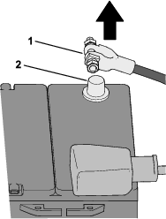
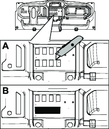
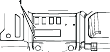
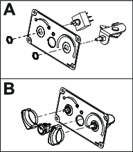
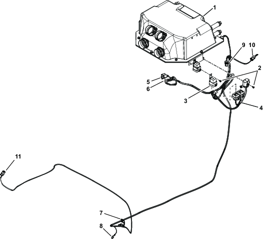
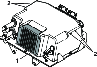
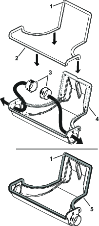
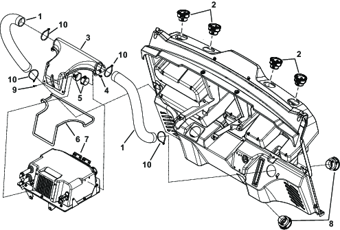
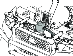
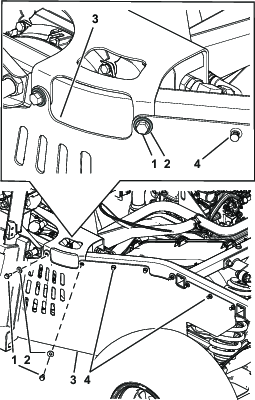
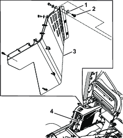
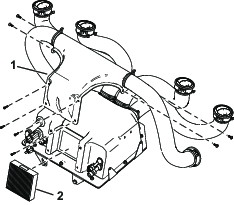
    1. Remove the air-intake cover from the HVAC box assembly (Figure 52).

      g419375
    2. Gently remove the filter from the HVAC box assembly.

      Note: Do not attempt to clean the filter.

    3. Inspect the new filter for damage by looking into the filter while shining a bright light on the outside of the filter.

      Note: Holes in the filter appear as bright spots. Inspect the element for tears, an oily film, or damage to the rubber seal. If the filter is damaged, do not use it.

      Note: Use care when handling the filter to avoid damaging or deforming it.

    4. Carefully install the filter.

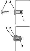
    5. Install the air-intake cover onto the HVAC box assembly with the corresponding hardware.

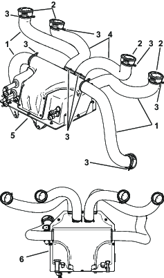
    Cleaning the HVAC Box

    Important: Do not get the HVAC box or components wet.