Setup
Opening the Crate
-
Lower the ends of the crate.
-
Remove the retaining straps.
-
Remove the plastic ties around the hopper handles.
Removing the Machine from the Crate
Parts needed for this procedure:
| Rear caster wheel | 1 |
| Bolt (1/2 x 13 inches) | 1 |
| Locknut (1/2 inch) | 1 |
Driving the Machine Off the Crate
Caution
The mower deck is shipped in the Up position, but it is not latched. Removing shipping reinforcements without supporting the front of the deck causes the deck to drop, which may result in injury or property damage.
Always securely support the front of the deck while setting up the machine.
Note: Ensure that the discharge tube does not catch on the crate when driving the machine off the crate (Figure 4).
-
Remove the rear caster-wheel assembly from inside the hopper.
-
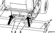
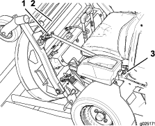
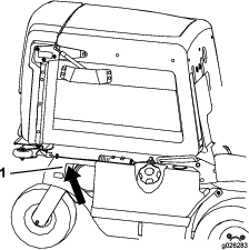
Remove the bolt holding the rear-frame support to the frame (Figure 1).
Caution
Raising the mower deck for service or maintenance relying solely on mechanical or hydraulic jacks could be dangerous. The mechanical or hydraulic jacks may not support the machine or may malfunction, allowing the machine to fall and cause injury.
Do not rely solely on mechanical or hydraulic jacks for support. Use adequate jack stands or equivalent support.
-
Raise the rear of the machine approximately 25.4 to 30.5 cm (10 to 12 inches) and support it with jack stands or equivalent support (Figure 1).
-
Remove and discard the rear-frame support, located behind the drive tires, from the machine.
-
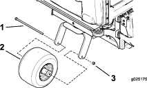
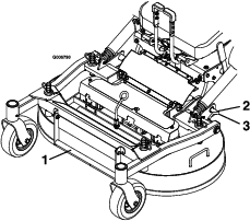
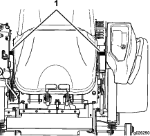
Install the rear caster wheel to the rear caster fork with a bolt (1/2 x 13 inches) and locknut (1/2 inch) (Figure 2).
-
Torque the bolt to 90.8 to 112.5 N∙m (67 to 83 ft-lb).
-
Carefully remove the jack stands and lower the machine.
Important: Ensure that the mower deck is in the upright position before raising the front of the machine.
-
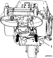
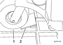
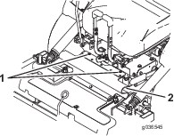
Raise the front of the machine and support it with jack stands or an equivalent support (Figure 3).
Note: Lift the mower deck just enough to remove the deck support and to insert other supports into the crate opening.
-
Remove and discard the deck support from under the rear deck rollers.
Note: Before lowering the deck into the operating position (steps 10 through 14), ensure that the crate opening under the mower deck is fully covered.
-
Place a plywood sheet (58.4 cm x 81.3 cm or 23 inches x 32 inches), or similar support, over the opening to provide support for the deck when you drive the machine off the crate (Figure 4).
-
Carefully remove the jack stands and lower the machine.
-
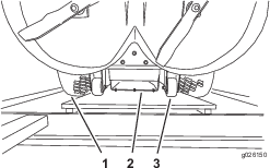
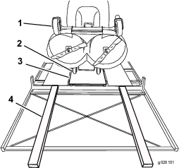
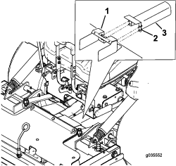
While supporting the mower deck, remove and discard the 2 side struts, mounting brackets, and their hardware on both sides of the seat (Figure 5).
-
Remove and discard the strut located between the front deck-support pins (Figure 5).
-
With the deck-locking pins pulled out in the unlock position, carefully lower the deck (Figure 6).
-
Push the deck-locking pins inward and rotate them forward to securely lock the deck in the lowered position.
-
Raise the mower deck to the highest height-of-cut position.
-
Install pieces of wood, to form a ramp, in front of the rear tire (Figure 7).
-
To form a ramp, place 2 long pieces of wood in front of each front-caster tire (Figure 8).
Note: Ensure that the discharge tube does not catch on the crate when driving the machine off the crate (Figure 4).
Warning
Operating the mower without the locking pins securely latched can result in the mower deck folding up unexpectedly. The mower deck folding up unexpectedly can cause serious injury.
Always operate the mower with the locking pins securely latched.
-
Drive the machine off the crate.
Removing the Machine from the Crate Using a Hoist
Caution
The mower deck is shipped in the Up position, but not latched. Removing shipping reinforcements without supporting the front of the deck causes the deck to drop, which may result in injury or property damage.
Always securely support the front of the deck while setting up the machine.
-
Remove the rear caster-wheel assembly from inside the hopper.
-
Remove the bolt holding the rear frame to the crate (Figure 11).
-
Lift the front of the hopper up.
Note: Use care when hoisting the machine to prevent damaging the hopper.
-
Using the hoist, lift the machine at the location shown in Figure 9.
Caution
Raising the mower deck for service or maintenance relying solely on mechanical or hydraulic jacks could be dangerous. The mechanical or hydraulic jacks may not be enough support or may malfunction allowing the machine to fall, which could cause injury.
Do not rely solely on mechanical or hydraulic jacks for support. Use adequate jack stands or equivalent support.
-
Raise the rear of the machine approximately 25.4 to 30.5 cm (10 to 12 inches) and support it with jack stands or equivalent support (Figure 10).
-
Remove and discard the rear-frame support and its hardware which is located behind the drive tires.
-
Install the rear caster wheel to the rear caster fork with a bolt (1/2 x 13 inches) and locknut (1/2 inch) As shown in Figure 11.
-
Torque the bolt to 90.8 to 112.5 N∙m (67 to 83 ft-lb).
-
Carefully remove the jack stands and lower the machine.
-
Lower the front of the hopper.
-
Tilt the seat up.
-
Place the hoist hooks on each side of the seat as shown in Figure 12.
Important: Ensure the mower deck is in the upright position before raising the front of the machine.
-
Raise up the front of the machine, just enough to remove and discard the deck support from under the rear deck rollers.
-
Lower the machine to the ground.
-
Lift the front of the hopper up.
-
Using the hoist, lift the machine at the locations shown in Figure 9 and Figure 12.
-
Remove the crate from under the machine.
-
Lower the machine to the ground.
-
While supporting the mower deck, remove and discard the 2 side struts, mounting brackets, and their hardware on both sides of the seat (Figure 13).
-
Remove and discard the strut located between the front deck-support pins (Figure 13).
-
With the deck-locking pins pulled out in the unlock position, carefully lower the deck (Figure 14).
-
Push the deck-locking pins inward and rotate them forward to securely lock the deck in the lowered position.
Installing the ROPS
Parts needed for this procedure:
| ROPS Kit (sold separately) | 1 |
Install the ROPS Kit as described in the Installation Instructions for the kit.
Installing the PTO-Shaft Guards
Parts needed for this procedure:
| Long guard | 1 |
| Guard | 1 |
| Bolt (1/4 x 1 inch) | 4 |
| Flat washer (1/4 inch) | 4 |
| Retainer nut (1/4 inch) | 4 |
Note: This procedure is only for international machines.
Note: The guards are located in the hopper of the machine.
Note: The guards are shipped assembled together with the parts listed above. Ensure the guards are installed after lowering the mower deck.
-
Shut off the engine, wait for all moving parts to stop, and remove key. Engage the parking brake.
-
Lower the mower deck.
-
Loosen the bolts attached to the rubber guard (Figure 15).
-
Fold the guard forward.
-
Install the metal guards with the attached bolts shown in Figure 16.
-
Install the rubber guard with the bolts (Figure 15).
Checking the Tire Pressure
Pressure: 103 kPa (15 psi)
Note: Check the tire pressure before starting the machine. Refer to your Operator’s Manual for the correct tire type, correct air pressure needed, and procedure.
Checking the Engine-Oil Level
Before you start the engine and use the machine, check the oil level in the engine crankcase; refer to Servicing the Engine-Oil Level in the Operator's Manual.
Checking the Torque of the Wheel Lug Nuts
Before you start the engine and use the machine, check the wheel lug nut torque; refer to Checking the Wheel Lug Nuts in the Operator's Manual
Installing the Battery
Parts needed for this procedure:
| Wing nut (1/4 inch) | 2 |
Caution
Battery electrolyte contains sulfuric acid, which is poisonous and can cause severe burns. Swallowing electrolyte can be fatal or if it touches skin can cause severe burns.
-
Wear safety glasses to shield eyes and rubber gloves to protect skin and clothing when handling electrolyte.
-
Do not swallow electrolyte.
-
In the event of an accident, flush with water and call a doctor immediately.
Warning
If the ignition is in the ON position, there is potential for sparks and engagement of components. Sparks could cause an explosion or moving parts could accidentally engage causing personal injury.
Be sure that the ignition switch is in the OFF position before charging the battery.
Locate the battery-mounting hardware and install the negative battery cable. Refer to Installing the Battery in the Operator's Manual.
Note: If the positive cable is also disconnected, connect the positive (red) cable to the positive battery terminal first, then the negative (black) cable to the negative battery terminal. Slip the insulator boot over the positive terminal.
Note: If time does not permit charging the battery, or if charging equipment is not available, connect the negative battery cable and run the vehicle continuously for 20 to 30 minutes to sufficiently charge the battery.
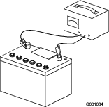
Charging the Battery
Warning
Charging the battery produces gasses that can explode and cause serious injury.
-
Keep cigarettes, sparks, and flames away from the battery.
-
Make sure that the ignition switch is off.
-
Ventilate when charging or using the battery in an enclosed space.
Important: Do not run the machine with the battery disconnected; electrical damage may occur to the engine.
Charge the battery. Refer to the Operator's Manual for instructions.
Checking the Hydraulic Fluid
The machine is shipped with hydraulic fluid in the reservoir.
-
Check and ensure the reservoir has hydraulic fluid.
-
If needed add Toro HYPR-OIL™ 500 hydraulic fluid.
-
Run the machine for approximately 15 minutes to allow any extra air to purge out of the hydraulic system.
-
Wait until the machine cools before checking the hydraulic fluid.
-
Tilt the hopper up.
-
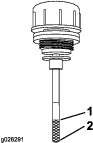
Remove the hydraulic reservoir cap.
-
Wipe the dipstick clean and insert the cap back into the hydro.
-
Lightly tighten the cap.
-
Remove the cap again and check the level of the fluid on the dipstick (Figure 18).
-
Check the hydraulic reservoir and if necessary fill the reservoir to the appropriate level with Toro HYPR-OIL™ 500 hydraulic fluid.
-
If the dipstick fluid level is at the Add mark, add hydraulic fluid. Do not overfill.
-
Replace the hydraulic reservoir cap and tighten until snug. Do not overtighten.
Checking the Machine for Grease
Parts needed for this procedure:
| No. 2 lithium grease (Purchase separately.) | 1 tube |
Before you use the machine, check the machine for grease; refer to Lubrication in the Operator's Manual.
Checking the Machine Before Delivery to the Customer
Before delivering the machine to the customer, ensure that you perform or have performed the procedures listed in the following table and initial each when finished. Refer to the Operator's Manual for instructions on performing these procedures.
| Initial | Check Procedure |
| Check the tire pressure. | |
| Check the level of the machine. | |
| Check the mower-deck gearboxes for fluid. | |
| Check the engine-oil level. | |
| Check the hydraulic-fluid level. | |
| Check the adjustment of the parking brake. | |
| Ensure that the machine tracks correctly; refer to the Operator's Manual for the adjustment procedure. | |
| Check the safety interlock system; refer to the Operator's Manual. | |
| Ensure that the PTO works. | |
| Check all fasteners that you installed to ensure that they are tight. |
When you finish setting up the machine, sign and date in the space provided below:
Delivering the Machine to the Customer
Parts needed for this procedure:
| Operator's Manual | 1 |
| Engine owner's manual | 1 |
| Registration card | 1 |
| Operator training material | 1 |
| Key | 2 |
At delivery, fill in the model and serial number, complete the items listed in the following table, and initial each when finished.
| Dealer Initial | Customer Initial | Check Procedure | ||
|---|---|---|---|---|
| Show the customer where the following features are located and how they function: | ||||
| • | Fuel tank | |||
| • | Oil fill cap/Oil dipstick | |||
| • | Spark plug(s) | |||
| • | Engine-oil filter | |||
| • | Engine-oil drain | |||
| • | Fuel gauge, valve and hose | |||
| • | Air filter | |||
| • | Hydraulic-fluid reservoir | |||
| • | Hydraulic filter | |||
| • | Battery | |||
| • | Ignition switch | |||
| • | Throttle lever | |||
| • | Choke (if applicable) | |||
| • | Power takeoff (PTO) | |||
| • | Motion-control levers | |||
| • | Parking brake | |||
| • | Height-of-cut | |||
| • | Adjustable seat | |||
| • | Hydraulic-bypass valves | |||
| • | Mower deck baffle | |||
| Refer to theOperator's Manual to point out safety procedures, operation, and maintenance procedures. | ||||
| Review the warranty statement as shown in the Operator's Manual. | ||||
| Describe the post sale service procedures for your store. | ||||
| Assist the customer in filling out and mailing the registration card or register online at www.Toro.com | ||||
| Make sure that the customer receives the Operator's Manual, Engine Owner's Manual, Set Up Instructions, and operator training material. | ||||
| Make sure the customer knows the Parts Catalog is available at www.Toro.com. | ||||
| Assist the customer in loading the machine. | ||||
Note: When you, the dealer representative, have finished delivering the machine to the customer, sign and date in the space provide below and keep a copy of this page for dealer records. Also, the dealer must remind the customer to use a full-width trailer ramp to load the machine.