Disclaimers and Regulatory Information
 |
| |
| CALIFORNIA |
| |
| Proposition 65 |
| |
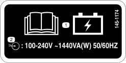
| The power cord on this product contains lead, a chemical known to
the State of California to cause birth defects or other reproductive
harm. Wash hands after handling. |
| |
| Battery posts, terminals, and related accessories contain lead and
lead compounds, chemicals known to the State of California to cause
cancer and reproductive harm. Wash hands after handling. |
| |
| Use of this product may cause exposure to chemicals known to the
State of California to cause cancer, birth defects, or other reproductive
harm. |
| |
FCC
This device complies with Part 15 of the FCC Rules. Operation is subject to the following conditions: (1) this device may
not cause harmful interference, and (2) this device must accept any interference received, including interference that may
cause undesired operation. Changes or modifications not expressly approved by Toro could void the user’s authority to operate the equipment.
In addition, while in charging mode this equipment has been tested and found to comply with the limits for a Class B digital
device, pursuant to Part 15 of the FCC rules. These limits are designed to provide reasonable protection against harmful interference
in a residential installation. This equipment generates, uses and can radiate radio frequency energy and, if not installed
and used in accordance with the instructions, may cause harmful interference to radio communications. However, there is no
guarantee that interference will not occur in a particular installation. If this equipment does cause harmful interference
to radio or television reception, which can be determined by turning the equipment off and on, the user is encouraged to try
to correct the interference by one or more of the following measures:
- Reorient or relocate the receiving antenna.
- Increase the separation between the equipment and receiver.
- Connect equipment into an outlet on a circuit different from that to which the receiver is connected.
- Consult the dealer or an experienced radio/TV technician for help.
Intended Use
This machine is intended to be used by professional, hired operators on indoor and outdoor improved surfaces in commercial
applications. It is primarily designed to move concrete, mortar, gravel, dirt, or debris around job sites. Using this product
for purposes other than its intended use could prove dangerous to you and bystanders.
Read this information carefully to learn how to operate and maintain your product properly and to avoid injury and product
damage. You are responsible for operating the product properly and safely.
Getting Help
Visit www.Toro.com for product safety and operation training materials, accessory information, help finding a dealer, or to register your product.
Whenever you need service, genuine Toro parts, or additional information, contact an Authorized Service Dealer or Toro Customer Service and have the model and serial numbers of your product ready. These numbers are located on the serial plate
on your product  . Write the numbers in the space provided.
With your mobile device, you can scan the QR code on the serial number decal (if equipped) to access warranty, parts, and
other product information.
|
Model Number:
|
|
Serial Number:
|
|
Manual Conventions
This manual identifies potential hazards and has safety messages identified by the safety-alert symbol, which signals a hazard
that may cause serious injury or death if you do not follow the recommended precautions.
This manual uses 2 words to highlight information. Important calls attention to special mechanical information and Note emphasizes general information worthy of special attention.
Safety Alert Classifications
The safety-alert symbol shown in this manual and on the machine identifies important safety messages that you must follow
to prevent accidents.
Safety-alert symbol appears above information that alerts you to unsafe actions or situations and is followed by the word
DANGER, WARNING, or CAUTION.
 |
Danger |
|
Danger indicates an imminently hazardous situation which, if not avoided, will result in death or serious injury.
|
Warning |
|
Warning indicates a potentially hazardous situation which, if not avoided, could result in death or serious injury.
|
Caution |
|
Caution indicates a potentially hazardous situation which, if not avoided, may result in minor or moderate injury.
General Safety
- Read and understand the contents of this Operator’s Manual before starting the machine.
- Do not operate the machine without all guards and other safety protective devices in place and functioning properly on the
machine.
- Park the machine on a level surface, lower the hopper, shut off the machine, and remove the key (if applicable) before leaving
the operating position.
- Keep your hands and feet away from moving parts. If possible, do not make adjustments with the machine running.
Improperly using or maintaining the machine can result in injury.
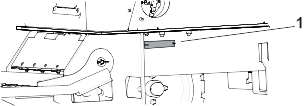
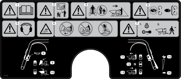
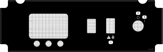
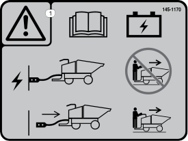
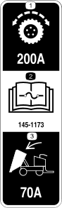
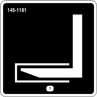
Safety and Instructional Decals
 |
Safety decals and instructions are easily visible to the operator and are located near any area of potential danger. Replace
any decal that is damaged or missing.
|
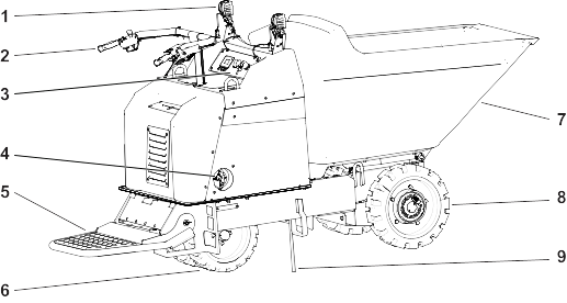
G380315
- Work lights
- Handle bars
- Control panel
- Electrical service disconnect switch
- Operator platform
- Steering tires
- Hopper
- Drive tires
- Anti-static strap
Controls
Electrical Service Disconnect Switch
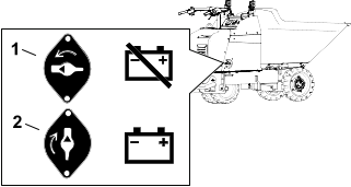
G387210
- Off—to de-energize the machine electrically
- On—to energize the machine electrically
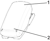
Directional Switch
G380320
- Drive forward
- Neutral
- Drive backward
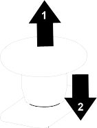
Dump Controls
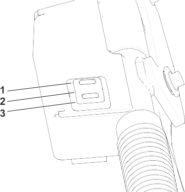
G380321
- Dump hopper
- Lower hopper
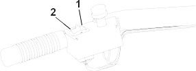
Emergency Stop
G380319
- Pull to enable the machine.
Note: Turn the key to the off then on position to continue operating the machine.
- Push to immediately shut off the machine.
Key Switch
G380323
- Turn the machine off.
- Turn the machine on.
Display
Display Icon Descriptions
|
|
Menu access
|
|
|
Next
|
|
|
Previous
|
|
|
Scroll down
|
|
|
Enter
|
|
|
Increase
|
|
|
Decrease
|
|
|
Exit menu
|
|
|
Check PIN entry
|
|
|
Parking brake is engaged.
|
|
|
Hour meter
|
|
|
Battery voltage
|
|
|
Battery charge—each solid bar represents the change in 10% increments.
|
Display Main Menu
|
Faults
|
A list of the recent machine faults. Refer to the Service Manual or your Authorized Service Dealer for more information on
the faults menu.
|
|
Service
|
Machine information such as hours of use and other similar numbers.
|
|
Diagnostics
|
Displays the state of each machine switch, sensor, and control output. This tells you which machine controls are on and off
which assists in troubleshooting.
|
|
Settings
|
Customize and modify configuration variables on the InfoCenter display.
|
|
About
|
Lists the model number, serial number, and software version.
|
Display Faults Menu
|
Current
|
Lists the total number of key-on hours (i.e., hours that the key has been in the ON position).
|
|
Last
|
Indicates the last key-on hour that the fault occurred on.
|
|
First
|
Indicates the first key-on hour that the fault occurred on.
|
|
Occurrences
|
Indicates the number of fault occurrences.
|
Display Service Menu
|
Hours
|
Lists the total number of hours that the key and motor have been on and the traction controls have been engaged.
|
|
Counts
|
Lists the number of times the motor has been started and the amperage hours for the battery.
|
|
Traction Pedal
|
Lists the steps to calibrate the traction pedal.
|
|
Steering Wheel
|
Lists the steps to calibrate the steering wheel.
|
Display Diagnostics Menu
|
Battery
|
Indicates the inputs and outputs for the battery. Inputs include the current battery voltage; outputs include the battery
current and percentage state of charge.
|
|
Left Motor
|
Indicates the speed and current of the left motor.
|
|
Right Motor
|
Indicates the speed and current of the right motor.
|
Display Settings Menu
|
Units
|
Indicates the inputs and outputs for the battery. Inputs include the current battery voltage; outputs include the battery
current and percentage state of charge.
|
|
Language
|
Controls the language used on the InfoCenter.
|
|
Brightness
|
Controls the brightness of the LCD display.
|
|
Contrast
|
Controls the contrast of the LCD display.
|
|
Protected Menus
|
Allows you to access protected menus by inputting a passcode.
|
Display About Menu
|
Model
|
Lists the model number of the machine.
|
|
Serial
|
Lists the serial number of the machine.
|
|
Software
|
Lists the part number and software revision.
|
|
Left Motor
|
Lists the part number and software revision of the motor controller.
|
|
Battery
|
Lists the part number software revision of the battery
|
Specifications
Note: Specifications and design are subject to change without notice.
|
Width (single wheel)
|
80.65 cm (31.75 inches)
|
|
Width (dual wheels)
|
106.7 cm (42 inches)
|
|
Length (with the platform up)
|
241.3 cm (95 inches)
|
|
Length (with the platform down)
|
282 cm (111 inches)
|
|
Height
|
139.7 cm (55 inches)
|
|
Weight
|
694 kg (1,530 lb)
|
|
Hopper capacity
|
0.40 m3 (14 ft3)
|
|
Maximum load
|
1136 kg (2,500 lb)
|
|
Wheelbase
|
104 cm (41 inches)
|
|
Discharge height
|
16.5 cm (6.5 inches)
|
Attachments/Accessories
A selection of Toro approved attachments and accessories is available for use with the machine to enhance and expand its capabilities. Contact
your Authorized Service Dealer or authorized Toro distributor or go to www.Toro.com for a list of all approved attachments and accessories.
To ensure optimum performance and continued safety certification of the machine, use only genuine Toro replacement parts and accessories.
Note: Determine the left and right sides of the machine from the normal operating position.
Maintenance Safety
- Park the machine on a level surface, engage the parking brake (if applicable), shut off the machine, and remove the key. Wait
for all movement to stop and allow the machine to cool before adjusting, servicing, cleaning, or storing the machine.
- Do not make repairs or adjustments on the machine unless you are specifically trained and authorized to do so.
- Support the machine with jack stands whenever you work under the machine.
- Carefully release pressure from components with stored energy.
- Use the cylinder lock to secure the hopper in the raised position.
- Never tamper with safety devices.
- To ensure safe, optimal performance of the machine, use only genuine Toro replacement parts.
- Seek immediate medical attention if fluid is injected into skin. Injected fluid must be surgically removed within a few hours
by a doctor.
- Ensure that all hydraulic-fluid hoses and lines are in good condition and all hydraulic connections and fittings are tight
before applying pressure to the hydraulic system. Keep your body and hands away from pinhole leaks or nozzles that eject high-pressure
hydraulic fluid.
- Use cardboard or paper to find hydraulic leaks.
- Safely relieve all pressure in the hydraulic system before performing any work on the hydraulic system.
- Modifying this machine in any manner may affect machine operation, performance, durability, or its use, and result in injury
or death.
- Contain hazardous material spills immediately according to hazardous materials regulations.
- After performing maintenance on the machine, check its performance in an authorized area away from vehicular and pedestrian
traffic.
- Before returning the machine to service, follow the recommended procedures.
- Regularly inspect a machine designed and approved for use in hazardous areas to ensure that it has its original and approved
safe-operating features.
- Maintain and keep all plates, tags, and decals with capacity, operation, and maintenance information in legible condition.
- Inspect and maintain the battery, motor, controllers, switches, safety protective devices, electrical wiring, and connections
according to the instructions.
- Keep the machine clean to minimize hazards and make inspecting the machine for servicing easier.
- Ensure that the extension cord plugs are in good condition and are not hot from operation. Do not use a damaged or worn extension
cord.
Recommended Maintenance Schedule
|
After the first 50 hours
|
|
144-6880 |
1 |
Gear oil |
|
Before each use or daily
|
Check the hydraulic fluid level.
|
- |
- |
- |
|
|
- |
- |
- |
|
Check for loose fasteners.
|
- |
- |
- |
|
Every 40 hours
|
|
139-7731 |
1 |
Anti-static strap |
|
|
- |
- |
- |
|
|
- |
- |
- |
|
|
- |
- |
- |
|
Every 50 hours
|
|
- |
- |
- |
|
Every 500 hours
|
|
144-6880 |
1 |
Gear oil |
|
|
505-136 |
1 |
Hydraulic fluid |
|
Every 1,500 hours
|
Replace all moving hydraulic hoses.
|
144-1736 |
1 |
Hydraulic hose |
|
144-1737 |
1 |
Hydraulic hose |
|
Yearly or before storage
|
Touch up chipped paint.
|
361-9 |
1 |
Paint |
|
361-10 |
1 |
Paint |
|
|
505-136 |
1 |
Hydraulic fluid |
Pre-Maintenance Procedures
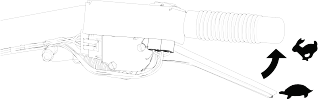
Retrieving a Machine
In an emergency, you can push or tow the machine.
Note: Do not tow the machine on a slope; the wheels will spin freely when you remove the gear.
-
Chock the wheels.
-
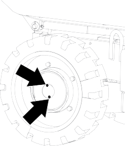
Remove the gearbox cover.
-
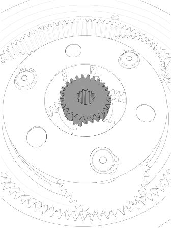
Remove the gear from the gearbox.
-
Install the gearbox cover to prevent contamination.
-
Tow the machine as required using the tie down locations.
-
Remove the gearbox cover.
-
Clean and install the gear in the gearbox and install the gearbox cover.
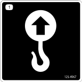
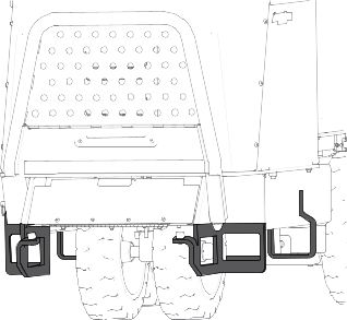
Lifting the Machine
Lifting the Machine with a Forklift
Ensure that the hopper is empty before lifting the machine.
-
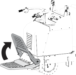
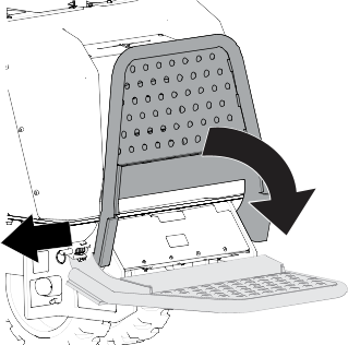
Place the platform in the raised position.
-
Lift the machine using the side or rear pockets.
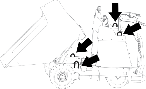
Lifting the Machine with a Hoist
Ensure that the hopper is empty before lifting the machine.
-
Place the platform in the raised position.
-
Place the hopper in the dump position.
-
Install the cylinder lock.
-
Attach a chain or straps to each of the lift points.
-
Remove any slack in the chains or straps to ensure that the machine is properly balanced.
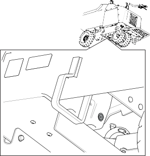
Using the Cylinder Lock
Installing the Cylinder Lock
-
Park the machine on a level surface, move the motion-control levers to the Neutral-lock position, and fully raise the hopper.
-
Remove the 2 cotterless pins securing the cylinder lock to the machine.
-
Slide the cylinder lock over the lift-cylinder rod and secure with the cotterless pins.
Removing and Storing the Cylinder Lock
Remove the cylinder lock from the lift-cylinder rod and fully secure it in the storage position before operating the machine.
-
Start the machine.
-
Fully raise the hopper.
-
Shut off the machine.
-
Remove the cotterless pins securing the cylinder lock.
-
Place the cylinder lock on the posts inside the machine frame and secure with the cotterless pins.
-
Lower the hopper.
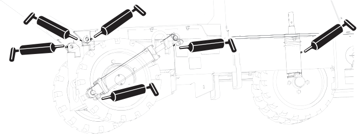
Lubrication
Greasing the Machine
Grease Type: General-purpose grease.
Note: Remove the blue protection caps, if applicable, before greasing and replace when finished.
-
Park the machine on a level surface.
-
Shut off the machine.
-
Clean the grease fittings with a rag.
-
Connect a grease gun to each fitting.
-
Pump grease into the fittings until grease begins to ooze out of the fittings (approximately 3 pumps).
-
Wipe up any excess grease.
Electrical System Maintenance
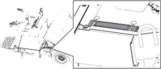
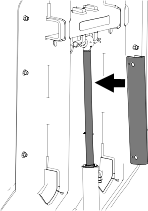
Checking the Anti-Static Strap
-
Park the machine on a level surface, lower the hopper, shut off the machine, and remove the key.
-
Check the anti-static strap and replace it if it is worn or missing.
Battery Service
Note: The machine is equipped with 3 lithium-ion batteries.
Dispose of or recycle lithium-ion batteries in accordance with local and federal regulations. If a battery requires service,
contact your Authorized Service Dealer for assistance.
The only user serviceable parts on a battery are the labels. If you are having problems with a battery, contact your Authorized
Service Dealer for assistance.
Battery Maintenance
|
Warning |
|
The batteries contain high voltage, which could burn or shock you.
- Do not attempt to open the batteries.
- Use extreme care when handling a battery with a cracked case.
- Use only the charger designed for the batteries.
The lithium-ion batteries hold a sufficient charge to perform intended work during its life span.
To achieve maximum life and use from your batteries, follow these guidelines:
Charging the Batteries
|
Danger |
|
Contact with water while charging the machine could cause electric shock, causing injury or death.
- Do not handle the plug with wet hands or while standing in water.
- Do not charge the batteries in the rain or in wet conditions.
|
Warning |
|
A damaged charger cord can cause an electrical shock or a fire.
Thoroughly inspect the charger cord before charging the machine. If the cord is damaged, do not charge the machine until you
obtain a replacement.
To reduce the risk of electric shock, this charger has a 3-prong grounded plug (type B). If the plug does not fit into the
wall receptacle, other grounded plug types are available; contact an Authorized Service Dealer.
Do not change the charger plug in any way.
Check the charger cord periodically for holes or cracks in the insulation. Do not use a damaged cord. Do not run the cord
through standing water or wet grass.
Charge the machine in temperatures ranging from 0° to 45°C (32° to 113°F).
The onboard charger will not function in temperatures outside of this range.
-
Park the machine in the designated location for charging.
-
Shut off the machine and remove the key.
-
Ensure that the electrical service disconnect switch is in the On position.
-
Open the cover for the charger cord storage.
-
Insert the charger plug into a grounded electrical outlet.
-
Observe the display to ensure that the batteries are charging.
-
When the machine reaches a sufficient level, disconnect the charger cord from the outlet.
-
Store the charger cord in the storage and close the cover.
-
Start the machine and verify the charge level using the display.
Charger Maintenance
All electrical repairs should be performed by an Authorized Service Dealer only.
The charger requires little maintenance other than protecting it from damage and weather.
- Clean the charger cord with a slightly damp cloth after each use.
- Coil the cord when not in use.
- Periodically examine the cord for damage, and replace it when necessary with Toro-approved parts.
Drive System Maintenance
Inspecting the Tires
-
Inspect tires for cuts, slashes, or bulges. Tires with defects need to be replaced or repaired for proper handling and safety.
Torquing the Wheel Lug Nuts
Torque the lug nuts in a crossing pattern.
-
Torque the front lug nuts to 67 to 78 N∙m (50 to 58 ft-lb).
-
Torque the rear lug nuts to 103 to 123 N∙m (76 to 91 ft-lb).
Drive-Motor Gear Oil Specifications
|
Oil Type
|
Mobil 626 SHC
|
|
Capacity
|
295.7 ml (10 fl oz) per gearbox
|
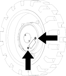
Changing the Drive-Motor Gear Oil
-
Start the machine and drive it for 5 minutes.
Note: This warms the gear oil so that it drains better.
-
Park the machine on a level surface so that a drain plug on the front motor is in the 6 o’clock position.
-
Shut off the machine and remove the key.
-
Place a drain pan under the drive motor.
-
Remove both plugs and allow the gear oil to drain.
-
Install the lower plug.
-
Fill the drive motor with gear oil through the open hole until the oil is up to the bottom of the hole.
-
Install the plug.
-
Repeat the procedure for the other drive motor.
-
Start the machine and drive it for a few minutes.
-
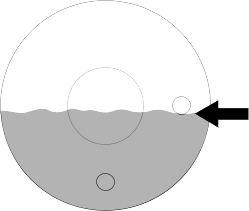
Park the machine on a level surface so that a drain plug is in the 3 o’clock position, shut off the machine, and remove the key.
-
Remove the plug in the 3 o’clock position and verify that the oil level is at the bottom of the oil-level check hole. Add oil as needed.
-
Install the plug and torque plugs to 5 to 6 N∙m (50 to 60 in-lb)
Hydraulic System Maintenance
Hydraulic Fluid Specifications
|
Hydraulic-Fluid type
|
Mobil ATF Dexron
|
|
Hydraulic fluid capacity
|
3.03 L (3.2 US qt)
|
The machine hydraulic tank is filled at the factory with approximately 3.03 L (3.2 US qt) of hydraulic fluid.
Checking the Hydraulic Lines
-
Check the hydraulic lines for leaks, loose fittings, kinked lines, loose mounting supports, wear, and deterioration. Make
necessary repairs before operating.
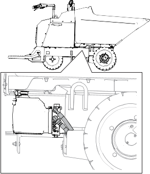
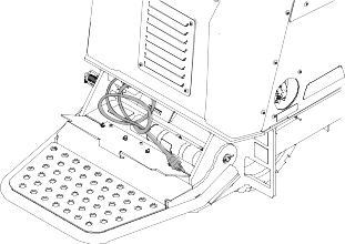
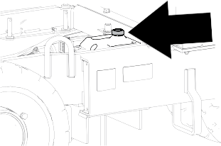
Changing the Hydraulic Fluid
|
Caution |
|
The hydraulic breather/filler cap is designed to pressurize the reservoir to 34 kPa (5 psi).
Loosen the cap slowly to avoid injury whenever adding oil or working on the hydraulic system.
-
Park the machine on a level surface and shut off the machine.
-
Remove the access panel.
-
Slowly loosen the hydraulic tank cap.
-
Place a large drain pan under the drain plug located at the bottom of the hydraulic tank.
-
Remove the drain plug and allow the oil to drain into the pan.
-
Install and tighten the drain plug.
Note: Dispose of the used oil at a certified recycling center.
-
Torque drain plug to 1.1 to 1.4 N∙m (10 to 12 in-lb).
-
Install the access panel.
-
Fill the hydraulic tank with the specified fluid.
-
Install the cap.
Cleaning
Removing Debris
-
Park the machine on a level surface, shut off the machine, and remove the key.
-
Clean any debris from the machine.
Blow the dirt out rather than wash it out. If you use water, keep it away from electrical items and hydraulic valves.
Clean electrical connectors using compressed air; do not use contact cleaner.
Washing the Machine
When pressure-washing the machine, do the following:
- Wear appropriate personal protective equipment for the pressure washer.
- Keep all guards in place on the machine.
- Avoid spraying at electronic components.
- Avoid spraying at edges of decals.
- Spray the exterior of the machine only. Do not spray directly into openings in the machine.
- Spray only the dirty parts of the machine.
- Use a 40-degree or larger spray nozzle. 40-degree nozzles are usually white.
- Keep the tip of the pressure washer at least 61 cm (2 ft) away from the surface being washed.
- Use only pressure washers with pressure below 13790 kpa (2000 psi) and flow below 7.6 L (2 US gallons) per minute.
- Replace damaged or peeling decals.
- Grease all grease points after washing.
Storage Safety
Park the machine on a level surface, engage the parking brake (if applicable), shut off the machine, and remove the key. Wait
for all movement to stop and allow the machine to cool before adjusting, servicing, cleaning, or storing the machine.
Preparing the Machine for Storage Over 30 Days
-
Park the machine on a level surface and lower the hopper.
-
Shut off the machine and remove the key.
-
Remove dirt and grime from the entire machine.
-
Grease the machine.
-
Check and tighten all fasteners. Repair or replace any worn, damaged, or missing parts.
-
Paint all scratched or bare metal surfaces with paint available from your Authorized Service Dealer.
-
Store the machine in a clean, dry garage or storage area. Remove the key and keep it in a memorable place.
-
Cover the machine to protect it and keep it clean.
Battery Storage Requirements
Note: You do not need to remove the batteries from the machine for storage.
Temperature Limits for Storage
|
45° to 55°C (113° to 131°F)
|
1 week
|
|
25° to 45°C (77° to 113°F)
|
3 weeks
|
|
-20° to 25°C (-4° to 77°F)
|
52 weeks
|
Temperatures outside of these ranges will damage your batteries.
The temperature that the batteries are stored at will affect their long-term life. Storage for long periods of time at extreme
temperatures will reduce the battery life. For temperatures above 25°C (77°F), only store the machine for the appropriate
amount of time indicated in the table.
- Before you store the machine, charge or discharge the batteries to between 40% and 60% (54.3V and 57.3V).
Note: A 50% charge is optimal to ensure a maximum battery life. When the batteries are charged to 100% before storage, the battery
life shortens.
If you anticipate that the machine will be stored for a longer period of time, charge the batteries to around 60%.
- For every 6 months of storage, check the battery-charge level and ensure that it is between 40% to 60%. If the charge is below
40%, charge the batteries between 40% to 60%.
- You can use a multimeter to check the charge level when the machine is off. Refer to the following table for the amount of
voltage that is equal to the charge level:
|
54.3V
|
40%
|
|
55.4V
|
50%
|
|
57.3V
|
60%
|
- After charging the batteries, disconnect the charger plug from power during storage to minimize the discharging of the batteries.
- The machine and charger will shut off after the batteries are fully charged and does not turn back on unless the charger cord
is disconnected and reconnected.
The machine does not drive.
|
Possible Cause
|
Corrective Action
|
|
The machine has been inactive for more than 30 seconds and is in sleep mode.
|
-
Set the drive control in the neutral position and back to the preferred direction.
|
|
One or more of the electrical connections are loose.
|
-
Check and tighten any loose connections.
|
The machine does not start.
|
Possible Cause
|
Corrective Action
|
|
The batteries need to be charged.
|
-
Check the InfoCenter for the battery status.
-
Charge the machine.
|
|
The electrical service disconnect switch is in the off position.
|
-
Turn the electrical service disconnect switch to the on position.
|
|
The emergency stop switch is engaged.
|
-
Disengage the emergency stop switch.
|
The machine batteries do not charge.
|
Possible Cause
|
Corrective Action
|
|
The electrical service disconnect switch is in the off position.
|
-
Turn the electrical service disconnect switch to the on position.
|
|
The charging cord plug is not fully plugged in.
|
-
Ensure that both sides of the charging cord is fully plugged in.
|
|
The charger is bad.
|
-
Contact your Authorized Service Dealer.
|
The throttle is not working properly.
|
Possible Cause
|
Corrective Action
|
|
The throttle needs to be calibrated.
|
-
Calibrate the throttle.
|
The steering is not working properly.
|
Possible Cause
|
Corrective Action
|
|
The steering needs to be calibrated.
|
-
Use the display to calibrate the steering system.
|
|
The steering linkage needs to be adjusted.
|
-
Check the steering linkage assembly for loose or missing hardware.
|
The hopper is not functioning properly.
|
Possible Cause
|
Corrective Action
|
|
The hydraulic fluid is low.
|
-
Check the hydraulic fluid.
|
|
There is air in the hydraulic system.
|
-
Bleed the air out of the hydraulic system.
|
|
The sensor is not working.
|
-
Adjust the sensor to 8 mm (3/4 inch) above the mounting bracket.
-
Check if the sensor has gone bad.
|
|
The switch is loose or disconnected.
|
-
Check the electric connections.
-
The switch has gone bad. Contact your Authorized Service Dealer.
|
|
The hydraulic system is damaged.
|
-
Contact your Authorized Service Dealer.
|